1
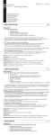
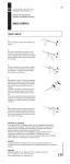
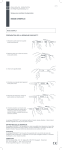
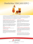
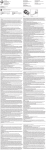
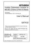
UK
User Instruction
Computer Assisted Local Analgesia
/
USER INSTRUCTION
CONGRATULATIONS ON YOUR NEW CALAJECT™!
Please read these instructions thoroughly before you start using your CALAJECT™
CALAJECT™ MAY ONLY BE USED BY TRAINED PERSONNEL authorized to
perform dental injections. For this reason, this manual does not include specific instructions in injection techniques. The manufacturer cannot be held liable for injuries
in patients due to unauthorized or incorrect use.
CONTENTS
1 Control unit
1 Handpiece with cord
1Footswitch
3 Cartridge barrels
1 Stand for handpiece
1 Charger
1 User instructions
DESCRIPTION OF CONTROL UNIT
FRONT PANEL WITH FINGER TOUCH DISPLAY
1. On/Off switch
1
2
2.Bar-scale for display of current injection pressure/resistance
3.Program selection 1, 2, 3
R
4.
Piston rod retraction. Returns the piston rod to start position
3
R
4
5
5.Charging and battery level indicator
REAR PANEL
6.Charger socket
7.Socket for handpiece
8.Connection to foot control or footswitch of the dental unit.
Some multi-function footswitches have a spare function (e.g. a call function) that can be used for operating
CALAJECT™
9.Volume control for sound signal
10. Sound aperture
6
7
10
8 9
RECOMMENDATION
It is recommended that new users carry out test injections in the air in order to familiarise themselves with the three different programs.
CLEANING
• The CALAJECT™ unit, the handpiece and the handpiece stand can be cleaned with a pad moistened with any surface disinfectant used in dental practice.
Do not immerse into liquid. Do not autoclave. The CALAJECT™ unit and the handpiece contain sensitive electronic components that do not withstand sterilization or immersion in liquid.
• The cartridge barrel can be autoclaved at max. 135°C.
The cartridge barrel may get a frosted appearance after a number of sterilizations. That will not
affect the strength of the cartridge barrel, but it is recommended to replace the barrel regularly
in order to keep a clear view to the cartridge.
If the cartridge barrel is damaged it should be replaced. Non-original barrels may not be used.
Replacement barrels (3 pcs. per pack) can be ordered over your CALAJECT™ dealer.
SERVICE WARRANTY & REPAIR
CALAJECT™ is covered by a 2-year guarantee on materials and construction.
Normal wear and tear and damages due to inadequate use or maintenance are not covered
by the warranty.
In the event of malfunction, please return the device to your CALAJECT™ dealer for repair.
OPTION
CALAJECT™ is operated by a separate foot control included in the package. But the system
can also be connected to the multi-function foot switch of your dental unit by your dental service
engineer. When connecting to the dental unit choose a potential free contact (relaycontact). The
assistant call function can often be used for this purpose. Connect to Calaject with a screened
cable less than 3m long and with a 3.5mm minijack plug.
GETTING STARTED
• Connect the handpiece cord plug to the CALAJECT™ rear panel
– the red dot on CALAJECT™ and the handpiece plug must be aligned.
Unplug by pulling the grooved sliding ring backwards (do not turn).
CALAJECT™ should not be placed close to devices that are sensitive to
- or generate - electromagnetic interference.
• Check the battery status on the display. Charging time approx. 3 hours.
Operating time approx. 5 hours.
•
Attach a needle on the cartridge barrel and insert an anaesthetic cartridge.
To avoid leakage at the membrane of the cartridge it is advised to screw on the needle first and then insert the cartridge. The cartridge barrel fits standard 1,7/1,8 ml dental cartridges and standard dental needles.
•
Mount the loaded cartridge barrel onto the handpiece. Before the barrel is screwed onto the handpiece, the piston rod should be retracted to starting position. It will
automatically return to starting position, when CALAJECT™ is turned on. The piston rod can also be returned to starting position by pressing ”R” on the display.
• Activate the foot control, until the anaesthetic solution is seen to come out of the needle.
• Select program. When the foot control is activated again, the chosen injection program will be active.
• CALAJECT™ will stop automatically, when the cartridge is empty.
Return the piston rod by pressing “R” at the display.
CALAJECT™ will stop automatically when it reaches the pre-programmed maximum pressure.
In such case, a long sound signal will be heard and the pressure bar-scale at the display will
turn off. Wait a moment or move the needle to a new position before you continue the injection.
PROGRAMS
PROGRAM 1 Recommended for intraligamental – and also palatal – analgesia
•
Activate the foot control
slow injection speed,
approx. 0,006 ml/sec.
Optional: Release / re-activate the foot control
the injection speed will increase to 0,009 ml/sec.
The PDL-technique requires a relatively high injection pressure initially. This is why Program 1 allows a substantially higher
injection pressure / resistance than program 2 and 3 before the automatic safety stop is activated.
R
R
R
TIP For intraligamental (PDL) analgesia it is recommended to dose 0,2 – 0,9 ml per root depending
on the size of the root and the expected duration of the procedure. For further guidance on the
PDL technique, we refer to the published literature on the subject.
TIP If the pressure has become so high that CALAJECT™ stops, the needle opening may have
been blocked and it is recommended to rotate the needle slightly in order to obtain a good flow.
TIP Auto pilot - five seconds after program start the sound signal is changing. This indicates that
you can release the foot control and let the auto pilot take over. You interrupt the injection by
re-activating the foot control. Note, auto pilot is only an option in program 1.
PROGRAM 2 Recommended for infiltration analgesia
•Initially 10 seconds with slow injection speed (approx. 0,006
ml/sec). During the subsequent 5 seconds it will gradually
increase to medium injection speed of 0,03 ml/sec.
R
• Aspirates automatically whenever the foot control is released. The small back-suction will also prevent after-dripping from the
needle.
R
R
PROGRAM 3 Recommended for regional nerve block analgesia
• Initially slow injection speed (approx. 0,006 ml/sec). By
releasing/re-activating the foot control in one swift movement, the
injection speed will increase gradually over the next 5 seconds to
high speed (approx. 0,04 ml/sec). Hereafter, high speed at every
stop/start.
• Aspirates automatically whenever the foot control is released.
R
R
R
ADDITIONAL INFORMATION
Table 1
Electromagnetic emissions
The “CALAJECT” is intended for use in the electromagnetic environment specified below. The customer or the user of the “CALAJECT” should assure that it is used in such an environment.
Emissions test
Compliance
Electromagnetic environment guidance
RF emissions
CISPR11
Group 1
The device uses RF energy only for its internal function. Therefore, its RF emissions are very low and are
not likely to cause any interference in nearby electronic
equipment.
RF emissions
CISPR11
Class B
Harmonic emissions
IEC 61000-3-2
Class A
The device is suitable for use in all establishments,
including domestic establishments and those directly
connected to the public low-voltage power supply
network that supplies buildings used for domestic purposes.
Voltage fluctuations/ Complies
flicker emissions
IEC 61000-3-3
Table 2
Electromagnetic immunity
The “CALAJECT” is intended for use in the electromagnetic environment specified below. The customer or the user of the “CALAJECT” should assure that it is used in such an environment.
Immunity test
IEC 60601
Test level
Compliance level
Electromagnetic
environment guidance
Electrostatic discharge ±6KV contact
(ESD)
±8KV air
IEC61000-4-2
±6KV contact
±8KV air
Floors should be wood,
concrete or ceramic tile.
If floors are covered with
synthetic material, the
relative humidity should
be at least 40%.
Electrical fast transient/ ±2KV for power supply
burst
lines
IEC61000-4-4
±1KV for input/output
lines
±2KV for power supply Mains power supply
quality should be that of
lines
±1KV for input/output typical residential area.
lines
Surge
IEC61000-4-5
±1KV differential mode
±2KV common mode
±1KV differential mode
±2KV common mode
Voltage dips, short interruptions and voltage
variations on power
supply input lines.
IEC61000-4-11
<5% UT for 0.5 cycle
40%UT for 5 cycles
70%UT for 25 cycles
<5%UT for 5 seconds
<5% UT for 0.5 cycle
40%UT for 5 cycles
70%UT for 25 cycles
<5%UT for 5 seconds
Mains power supply
quality should be that of
typical residential area.
3A/m
Power frequency magnetic fields should be that
of typical residential area.
Power frequency (50- 3A/m
60Hz) magnetic field.
IEC61000-4-8
Specifications:
Temperature range:
Charge::
10-14v/1ADC, medical Operating:
10 - 35’C
Storage:
-20 – 60°C
Output::0-4v/0,3ADC
Humidity:
10 – 95%
Classifikations:COUNCIL DIRECTIVE 93/42/EEC Class IIa
Standards:EN60601-1
Disposal: Separate collection for electronic equipment
Table 3
Electromagnetic immunity
The “CALAJECT” is intended for use in the electromagnetic environment specified below. The customer or the user of the “CALAJECT” should assure that it is used in such an environment.
Immunity
test
IEC 60601
Test level
Compliance
level
Electromagnetic environment
guidance
Portable and mobile RF communications
equipment should be used no closer to any
part of the device, including cables, than
the recommended separation distance calculated from the equation applicable to the
frequency of the transmitter.
Recommended separation distance
Conducted RF
IEC61000-4-6
3Vrms
150KHz to 80 MHz
d=1,17√ P
3Vrms
d=1,17√ P
80 MHz to Hz to 800 MHz
d=2,23√ P
Radiated RF
IEC61000-4-3
3V/can
80MHz to 2,5GHz
3V/m
800 MHz to 2,5 GHz
where P is the maximum output power rating of the transmitter in watts (W) according to the transmitter manufacturer and d
is the recommended separation distance in
meters (m).
Field strengths from fixed RF transmitters,
as determined by an electromagnetic site
surveya, should be less than the compliance
level in each frequency range.b
Interference may occur in the vicinity of equipment marked with the following symbol:
NOTE 1 At 80 MHz and 800 MHz, the higher frequency range applies.
NOTE 2 These guidelines may not apply in all situations. Electromagnetic propagation is affected
by absorption and reflection from structures, objects and people.
a
Field strengths from fixed transmitters, such as base stations for radio (cellular/cordless) telephones and land mobile
radios, amateur radio, AM and FM radio broadcast and TV broadcast cannot be predicted theoretically with accuracy.
To assess the electromagnetic environment due to fixed RF transmitters, an electromagnetic site survey should be considered. If the measured field strength in the location in which the device is used exceeds the applicable RF compliance
level above, the device should be observed to verify normal operation. If abnormal performance is observed, additional
measures may be necessary, such as re-orienting or relocating the device.
b Over the frequency range 150 kHz to 80 MHz, field strengths should be less than 3 V/m.
ADDITIONAL INFORMATION
Table 4
Recommended separation distances between portable and mobile RF
communications equipment and the “CALAJECT”
The device is intended for use in an electromagnetic environment in which radiated RF disturbances are controlled. The
customer or the user of the device can help prevent electromagnetic interference by maintaining a minimum distance
between portable and mobile RF communications equipment (transmitters) and the device as recommended below,
according to the maximum output power of the communications equipment
Rated maximum
output of
transmitter (W)
Separation distance according to frequency of transmitter m
150 kHz to 80 MHz
80 MHz to 800 MHz
800 MHz to 2,5 GHz
d = 1,17 P
d = 1,17 P
d = 3,5 P
0,01
0,12
0,12
0,35
0,1
0,37
0,37
1,11
1
1,2
1,2
3,5
10
3,7
3,7
11,1
100
12
12
35
For transmitters rated at a maximum output power not listed above the recommended separation distance d in metres
(m) can be estimated using the equation applicable to the frequency of the transmitter, where P is the maximum output
power rating of the transmitter in watts (W) according to the transmitter manufacturer.
NOTE 1
At 80 MHz and 800 MHz, the separation distance for the higher frequency range applies.
NOTE 2
These guidelines may not apply in all situations. Electromagnetic propagation is affected
by absorption and reflection from structures, objects and people.
TECHNICAL SPECIFICATIONS
Control unit
Handpiece
Length
95 mm
200 mm (incl. barrel)
Width
120 mm
Ø 12 mm
Ø 60 mm
Height
115 mm
Weight
750 g
50 g
410 g
Battery (Lithium-ion)
Charging time
34 mm
90-240 V – 50/60Hz
8 hours on each charge
Approx. 3 hours
Dental Cartridge
1,7/1,8 ml standard cartridges
Dental Needles
Standard M6 and 7/32”
Manufactured in Denmark by:
/
Gl. Vejlevej 59 . DK-8721 Daugaard
Tlf: +45 70 23 34 11 . Fax: +45 76 74 07 98
email: [email protected] . www.ronvig.com
Gl. Vejlevej 59 . DK-8721 Daugaard . Tel.: +45 70 23 34 11
Fax: +45 76 74 07 98 . E-mail: [email protected] . www.ronvig.com
0543
RØNVIG Dental Mfg. A/S. ALL RIGHTS RESERVED. B2110GB-06.15.U3
Nominal voltage
Stand