1
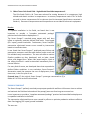
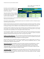
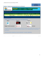
Customer Info
2012
80 Woodford St,
Newtown,
Port-of-Spain, Trinidad
Tel: 868-628-6346
Fax: 868-622-1912
A Universal Platform with communication built
built-in
in and systems integration
capability that controls any artificial lift device to perfectly match pump
speed with inflow in real time
Manage and Monitor Multiple
Devices from Anywhere
• ESPs
• PCPs
• Pump--Jacks
• Salt Water Disposal Systems
• Pipelines
• Tank Farms
• Gas Lift
• Plunger Lift
The Smart Pumper™
18000 Groeschke Road A-1
A
Houston, Texas 77084
Tel: 281-829-5559
5559
Fax: 281-578--0109
www.smartpumper.com
[email protected]
Automation for the Oil, Gas and Water Industries
Table of Contents
Mission Accomplished............................................................................................................................. 3
The Smart Pumper™ Automation Platform Overview ........................................................................... 3
Smart Pumper™ Development History .................................................................................................. 4
Field Testing ........................................................................................................................................... 4
Lessons Learned ..................................................................................................................................... 5
National Oil Company Pilot and Testimonial........................................................................................... 6
Smart Pumper™ Manufacturing ............................................................................................................. 8
Assembly of Automation Packages for Electric and Hydraulic Motors (5HP – 200HP) .......................... 8
Smart Pumper™ Automation Package Examples ................................................................................... 9
Operating the Smart Pumper™ Automation Package ........................................................................... 10
Field Installation and Training ................................................................................................................10
Our Houston Stock Items (For Automation) ..........................................................................................10
“Exhibit A” Summary of Features and Environmental Spec. ..................................................................11
“Exhibit B” PCPs, ESPs and Pump-Jacks .............................................................................................…. 13
“Exhibit C” Global Service Network ....................................................................................................... 16
2
Automation for the Oil, Gas and Water Industries
Mission Accomplished
The Smart Pumper™ team set out to design and mass produce a simple to use universal PLC platform for
the Oil, Gas and Water Industries that would “pump all wells perfectly” from the moment you turn it on
without step ladder programming. The team successfully produced a device that Automation, Process, and
Production Engineers can utilize within minutes of deployment to control and monitor any operation, both
onsite and remotely from any location.
The Smart Pumper™
Automation Platform Overview
The patent pending Smart Pumper™ is a powerful PLC that serves users as the Master to any VFD
(variable frequency drive) for regulating electric motor speed, hydraulic motors and hydraulic valves. It
also collects data from an array of sensor and metering
options.
The motor speed control is based on getting actual fluid level in
real time to the specific target you want to reach and maintain.
Users simply define timeframe and target fluid level and the
Smart Pumper™ will do the rest.
Manufactured in Dallas, Texas, the Smart Pumper™ has
received all necessary global certifications (2011) for
deployment including CE, CEE, Canadian, and Europe’s most
recent and stringent requirements to date.
The Smart Pumper™ was designed from the realization that maximizing profits in an artificial lift
environment could only be achieved through perfect pumping and collection of important data in real
time. We needed and wanted a simple to use, affordable solution to automate every well.
By creating a Universal Platform and combining everything into one powerful PLC with drivers for key
components that can also be added, we created a “Plug-N-Play Package” that:
1.
2.
3.
4.
5.
6.
7.
8.
9.
10.
11.
Is user friendly and easy to set up, providing desktop control within minutes
Controls any motor (electric and/or hydraulic)
Controls any VFD
Can control any form of artificial lift
Provides two way communication, built-into its board (cell, radio, satellite)
Provides secure private network tunnels to companies and country servers
Is supported by a global network (see “Network Coverage By”, Exhibit B)
Provides interface to desktop and mobile devices (laptop, iPad, iPhone)
Utilizes SQL R-2 (can use your paid license vs. having you pay more)
Provides server support (if you don’t have one or you want to pilot first)
Provides 20+ hard wired inputs from the start for:
a. (8) Analog definable and scalable channels supporting all A-D Sensors such as, PSI, temp,
vibration, water quality (salinity, pH), gas monitoring (H2S, CO2, methane, radon) and
3
Automation for the Oil, Gas and Water Industries
b.
c.
d.
e.
f.
more
(8) Digital definable and scalable channels
(4) Pulse counters (2) with modulation (metering clean and dirty signal)
Digital current loops (valve controls)
485 Maud Bus (to have a series of sensors on one network cable and control the VFD at
the same time)
RS235 (to allow automation engineers the capability of adding their improvements over
time)
See Exhibit A for more detail and visit www.smartpumper.com.
Smart Pumper Development History
The Smart Pumper™ was developed out of the need for consistent, precise & automatic pumping to
reduce OPEX and maximize production run times. It has been recognized that the only practical and
reliable method to manage wells is to control pump motor speeds using actual real time fluid levels
over time. .In each well the pump output potential needs to be evaluated and then continuously
redefined because of the dynamic nature of the fluids & pressures in the reservoirs. It has been found
that this process can be automated and has become the “best practice” from well completing to
plugging.
The first prototype of the Smart Pumper™ was built in the 1980’s in Texas. However, commercial
production was too expensive for low volume wells and the concept was shelved. In 2006,
advancements in chip and sensor technology prompted the development team to revisit the
concept. By 2007, 25 Smart Pumper™ prototypes were being produced in a lab in Dallas, and tested in
harsh environments with extreme temperatures and levels of moisture.
Trinidad and Tobago’s heavy oil fields were chosen for initial testing due to their extreme heat, high
humidity and dynamic reservoir conditions. The fluid level-based precision pumping test proved to be
a success. The team continued to advance the hardware concepts to produce a universal platform for
all sensor types and/or VFD. By 2011, the patent pending Smart Pumper™ was certified for USA,
Canada and Europe (CE, CEE, Canada). . Smart Pumper™ is currently manufactured in Dallas, Texas
with ISO 9000-certification, and is assembled in Houston with a variety of VFD’s (any HP) as Smart
Pumper™ Automation Solutions for ESPs PCPs and Pump Jacks.
Field Testing
Locations:
1. Trinidad: Parrylands Field, Block E – hot & humid
The Parrylands field contains heavy oil, which is difficult to produce because of viscosity and
sand-production problems that cause the inflow to change continuously. This makes it one of
the more difficult reservoirs to produce by pumping. Equipment in this area must withstand
very high humidity (90%) and temperatures (36o), not ideal for electronic equipment.
4
Automation for the Oil, Gas and Water Industries
2.
West Texas: Orla South Field – high altitude & variable temperatures
The Orla South Field in W. Texas was selected for testing because of its remoteness, high
altitude and drastic variation in temperatures. In summer, temperatures reach 170oF in direct
sun and in winter temperatures fall to sub-zero (see Environmental Specifications contained in
Exhibit A). Extremes in temperatures and low pressures are not ideal for electronic equipment.
Results:
To expedite installation in the fields, we found that it was
important to provide a “complete automated package”
prewired and tested before deployment.
The Smart Pumper™ matched pump output with well bore
inflow to optimally maintain desired fluid levels. Data logged
(35+ inputs) proved invaluable. Furthermore, Smart Pumper’s
automation eliminated human errors caused by intervention
based on insufficient data.
It was found that Smart Pumper™ predicted pump failure and
preemptive measures could be taken before pumps stuck and
this avoided costly interventions. The user was able to monitor
flowline problems as they developed, such as leaks, closed
valves, and plugged lines. When rods parted and/or a hole in
the tubing occurred it could be detected immediately from a
remote location.
For every kind of sensor, we developed alerts that responded to
defined failure conditions. In our evaluation, Smart Pumper™
Automation saved the operator the cost of deployment, many
times over, in the first year of use.
Pictured Item: (5) An original Smart Pumper™ prototype connected to (2) a
Baldor H-2 VFD on an electric drive head.
Lessons Learned
The Smart Pumper™ perfectly matched pump output speed with well bore inflow over time to achieve
and maintain the fluid level selected until the pump(s) wore out from long term normal use.
It was important to provide a “complete automated package” prewired and tested before deployment
to expedite installation in the fields.
The automation eliminated human error caused by efforts to optimize production without sufficient
data. Data logging (35+ inputs) proved invaluable.
The user can:
5
Automation for the Oil, Gas and Water Industries
•
Predict pump life before the pump fails.
•
See that a pump is about to become stuck before it does and schedule pre-emptive measures
to avoid costly rig time.
•
See flowline problems as they develop such as leaks, closed valves and plugged lines.
•
Determine remotely that you have parted rods and/or a hole in the tubing within moments of
the occurrence.
•
Define alerts and fault conditions for every kind of sensor.
Smart Pumper™ Automation paid for the cost of deployment through the many benefits provided
several times a year.
National Oil Company Pilot and Testimonial
Pilot Objective: Compare Smart Pumper™ Automation for ease of use, performance, quality control
and online web based automation. Compare economic evaluation of same with previously installed
well head systems. Evaluate, analyze and monitor Smart Pumper™ data transfer rate from remote
jungle swamp areas to company desktops and performance of automation.
Background: Prior to Pilot, Petroleum Engineers (PE)
monitored the well performance on a monthly basis in the
respective oil fields based on flow tests, pressure tests,
service information and other historical data for
optimization purposes. Reservoir Engineers (RE) also used
pressure data to monitor well behavior, and periodically
request that testing teams perform a pressure build test
so that necessary reservoir calculations and predictions
can be undertaken.
Long term testing of three systems was initiated. The well shown is 290w05 in the Calcutta Field.
DDH Smart Pumper™ solution turned out to be a low cost automated variable speed lifting option for
PCPs. The Smart Pumper™ can provide PE’s with FBHP, FBHT, RPM etc. to their desktop from remote
locations saving considerable time in the management of the wells. RE’s could also remotely activate
a pressure build up test and monitor their pressure surveys in real time from their desktop without
dispatching crews to go out and start, record, and then return to restart wells after a test period.
They could also make real-time adjustments to the programmed schedule of build-up and drawdown tests, thereby minimizing associated production loss.
6
Automation for the Oil, Gas and Water Industries
Analyses of the results:
1. User-friendly web based graphical interface accessible to those with proper user definition and
password for specific levels of authority: Administrator, Field Manager, PE, RE, Well Pumper
(Operator), Electrical, Maintenance.
2. Administrator access to Event log, Reports, Manage Well Page, and other aspects were easy to
navigate.
3. Response time to commands to change RPM or shutdown averaged 9.23 seconds and was
purely based on internet connection speed at our location.
4. Email as well as automated SMS can be programmed. Primary log parameters can be retrieved
from the well such as FBHB, FHBT, Volts, Hz, amps, RPM as well as secondary log parameters
like torque, theoretical flow and fluid level.
5. For pilot, data flow was from Smart Pumper to local cell provider Digicel into internet tunnel in
Suriname to Direct DriveHead Server in Houston and back.
6. Table I shows cost comparison between current installed system and Direct DriveHead/Smart
Pumper™. (DDH/SP was ½ the cost).
7. With Smart Pumper Automation installed on 290w05, there was a 21% increase in barrels
produced compared to prior 10 months primarily due to maintaining better actual real time
fluid level control. See Graph 1 and table 2 in full report.
8. Fluid level control via the variable frequency drive (VFD) linked to the Smart Pumper’s
proportional integral derivative (PID) controller is quite smooth. The point from which there is
a perturbation until this is corrected to the target level programmed matches; i.e., if you say
take 90 days, it takes 90 days and if you say take 10 days, it takes 10 days to target if the pump
is sized correctly.
9. Graph 4 shows the data retrieved from the online dashboard of well 290W05 is repeatable
within the 6 sigma (standard deviation) band.
10. During the 12 month pilot, there were no maintenance issues that hampered the functionality
of the drive head and/or the Smart Pumper Automation. A 100% uptime was registered. The
only issue was that the stuffing box required proper rope packing to prevent it from leaking and
National Oil Well Varco was asked to lower the weep hole on the housing so that the hose to
collection bottle would flow more freely. The manufacturer did this. Also a gear noise
developed from water penetrating an upper seal; however, the gear continues to operate and
Boston Gear, the manufacturer, has since redesigned the upper seal to prevent water entry.
Conclusion: The Smart Pumper™ Automation Package is user friendly and once installed virtually
immediately transferred the data to the online server with an average 9.23-second response time
per signal command or data retrieval. With the system installed we realized a reduction in travel
time and increased efficiency of labor by allowing workers to focus on other field duties. Control of
the fluid level to target was accomplished as programmed into the Smart Pumper™. It also
eliminated all unnecessary operator, PE and RE intervention with regards to “attempting” well
optimization. The DriveHead Smart Pumper system is much cheaper than Data Loggers that only log
data. The installed sensors and cables provided have worked properly for the past 12 months.
7
Automation for the Oil, Gas and Water Industries
Recommendations:
1. Increase Staatsolie (Maatshappij) Internet bandwidth so that Smart Pumper™ response time is
more immediate for future desktop users.
2. Implement the Smart Pumper™ on all wells with a production of 50 BOPD and more so that
immediate actions, troubleshooting, analyses, optimization or learning can take place. This will
eliminate the time needed for the field operators to download SRO data at each site and/or
shoot fluid levels with acoustic well analyses AWA or Echometers. With the Digital AWA or
Echometer there is no control over dependent variables such as foam content, density of gas,
and others, which can result in inaccurate fluid level measurements.
3. On new wells, plan deployment of the Smart Pumper™ from the start. It will reduce man-hours
required to bring new wells online per field in ratio with the installed Smart Pumpers. We can
redirect manpower to attend to other issues and as a result increase the number of wells under
operator control due to the time savings.
4. Request the Smart Pumper™ Automation Package(s) to have a pole mount option.
5. Install a two-day battery back-up to maintain sensor data logging and communication in case of
power failures. Set up email alert for this event and data log the frequency of power failures.
6. Have the Smart Pumper™ team utilize Staatsolie’s in-house server and create a private network
using Suriname cell service provider.
Smart Pumper™ Manufacturing
The Smart Pumper™ is manufactured in Dallas, Texas.
Site inspection and plant tour arranged by appointment only. Contact us if you desire to see the process of printing circuit
boards, assembly, software loading and testing prior to shipping.
Assembly of Automation Packages for Electric and Hydraulic Motors (5HP –
200HP)
Smart Pumper™ Automation Packages are assembled in Houston, Texas. The plug-and-play
automation package includes the following:
For Electric Motor Devices
• Nema Enclosure (Pole Mount) with Quick Connect for your power supply input
• Smart Pumper™ Automation Platform with communication and antennae
• 460V 3 Phase VFD of your choice with soft motor start and dynamic brake module
• 120V Transformer for cooling fan(s)
• 24V Transformer to power Smart Pumper™ and sensors
• Din Rail wired to Smart Pumper™ for sensor inputs
• Battery back-up (optional) 72 hrs.
8
Automation for the Oil, Gas and Water Industries
For Hydraulic Motor Devices
• Nema Enclosure (Pole Mount) with four 1” Quick Connects for fluid in, out, forward and reverse
• Smart Pumper™ Automation Platform with communication and antennae
• Selector valve (forward, neutral, reverse)
• Selector valve (automatic or manual)
• Needle valve (manual speed control)
• Proportional hydraulic motor valve
• 120V Transformer for cooling fan(s)
• 24V Transformer to power Smart Pumper™ and sensors
• Din Rail wired to Smart Pumper™ for sensor inputs
• Battery back-up (optional) 72 hrs.
Smart Pumper Automation Package Examples
After assembly each Smart Pumper™ Automation Package is tested against an electric and/or hydraulic
motor stand. This ensures that systems are wired and/or plumbed properly and that both automation
and manual modes are functioning properly. In addition, the Smart Pumper™ Communication link is
activated and established to the web interface at the factory to verify web control and data logging are
working properly. When the customer deploys, the Smart Pumper Automation Package is truly a plugin-and-play solution. Call us to set up a demonstration in Houston.
9
Automation for the Oil, Gas and Water Industries
Inside the Enclosure
10
Automation for the Oil, Gas and Water Industries
Operating the Smart Pumper Automation Package
Once installed, the Smart Pumper™ Plug-in-and-Play Automation Package will control any device and
can be accessed from your desktop within minutes without buying another thing. Use it on drive heads
for PCPs made by Weatherford without “E-Solution”, R&M, Oillift and others. Control Lufkin Pump
Jacks without Sam™. Control Franklin and other ESP’s without Siemens PLC board. Retrofit existing
hydraulic drive heads or hydraulic pumping units.
The simple to use “Open Platform” requires no step ladder programming; just select the target level
you want and the number of days to achieve target and the unit will perform this duty automatically –
perfectly matching pump output to inflow always.
The Smart Pumper™ interfaces with any A-D sensor, most Digital sensors, and most meters. See Smart
Pumpers User Manual.
Field Installation and Training
Installation Teams are located throughout North America and are deployed overseas from Houston
and Trinidad. The Smart Pumper™ team will provide first time users with set up experience and
training until their well completion teams can install for themselves.
Trans-Ocean container packing and shipping is also managed from the Smart Pumper™ Houston
assembly facility.
Our Houston Stock Items (For Automation)
•
•
•
•
•
•
•
•
•
•
Variable Frequency Controllers (VFDs) all brands drives range 5 – 200 HP
Electric motors 5 – 200 HP
Hydraulic selector and proportional valves and fittings
Misc. fittings, clamps, wellhead feed through components
Permanent downhole sensors
Surface sensors
Cabling and 4mm stainless tube wire for deploying sensors downhole
Straps and sensor protector clamps
Tubing anchors
Enclosures
“A one-stop-shop organized to deliver a complete artificial lift automation package with technical
installation support to minimize rig time and to get you pumping perfectly”.
11
Automation for the Oil, Gas and Water Industries
“Exhibit A” Summary of Features and Environmental Spec.
•
•
•
•
•
•
•
•
•
•
•
•
•
•
•
•
•
•
•
•
•
•
•
•
•
Automation software provided
Data logging and web interface to desktop provided
Two way communications provided (cell, satellite, radio selectable and built-in)
Two (2) Gigabyte SD Ram for long term data logging
16-bit Digital Signal Processor (DSP) for fast, smooth and dynamic response
256 kilobytes scratch pad memory
Real time clock syncs with server to back fill data logged
Downloadable to laptop through serial port
Built-in two way communication to the web to download remotely
Upload remotely to desktop for graphic reporting, Excel and table formats
Eight (8) analog inputs (Definable Sensor Array)
Eight (8) digital (4) In and (4) Out (Definable Sensors and Switches)
Four (4) pulse counters; two (2) with modulation. (Definable Meters and other Sensors)
Two digital to analog channels
Plus 485 interface with Maud Bus (to control any VFD and provide VFD data to desktop)
Drive-by wireless
Remote and on-site system diagnostics (well, VFD, motor, communications and sensors)
Alarms and fault setting with definable action
Smooth variable frequency (hertz) operation for precise control of motor and torque
Constant horsepower monitoring
Dynamic braking control options available for absorbing regenerated energy
Auto restart for quick restoration of operation
Integral DC link choke for sensor arrays and low total harmonic distortion
External heat sink available for all VFD packages
Air-to-air heat exchanger for cooling electronic equipment
Electrical
Input Supply
Smart Pumper 24 Volt DC
VFD
Voltage: Single and Three Phase 230, 380, 460, or 575 V AC (±10%)
Frequency: 47 to 63 Hz
Power Factor
Overall: 1.00 displacement power factor/0.94 overall power factor at all speeds
Output Rating
Voltage: Three Phase in the voltage range above
Frequency: Zero to 300 Hz variable frequency control
Smart Pumper Switching frequency: Programmed to command VFD to generate kHz adjustments required to achieve
desired fluid levels and to stop the VFD for Fault conditions.
VFD
Overload current: Constant torque (CT): 150% to 200% of rated for 1 minute maximum of 200% rated
Environmental Specifications
Operating temperature: 0° to 150° F (0° to 50° C)
Storage temperature: 5° to 158° F (–15° to 70° C)
Relative humidity: 5% to 95%
Serial Communications
12
Automation for the Oil, Gas and Water Industries
Asynchronous ports: EIA RS-232 and RS-422/485, isolated, 0.3 to 19.2 and 0.3 to 115.2 kbaud Standard: ANSI-x3.28-2.5-A4
and Modbus RTU protocols with MaxStream wireless communications
Protection Provided with Smart Pumper Package with VFD
• Motor overload
• Heat sink over temperature
• Temperature Logging with warnings and fault alarms
• Motor short circuit
• Power transistor fault
• Input overvoltage
• Logic power under voltage
• Input under voltage
• Memory malfunction
• Instantaneous overcurrent
• Processor execution fault
• Ground fault
• Facility faults can be easily set up using sensors for Flowline, Casing pressure, Separators, Tank Level, and other
points to reference that wire directly into the Smart Pumper cabling for easy utilization.
13
Automation for the Oil, Gas and Water Industries
“Exhibit B” PCPs, ESPs and Pump‐Jacks
Progressive Cavity Pumping
The Smart Pumper™ is configured to provide automation and monitoring features specifically designed for the
operation of any type of drive head used with progress cavity pumps (electric and hydraulic). The Smart
Pumper™ Automation Package has three modes: Automation, Manual, and Off that can be selected locally and
remotely. PCP Drives can also be operated from the VFD in local manual mode.
The Smart Pumper™ Automation generates motor speed commands to operate a drive head and PCP in direct
response to the slow down and/or speed up of actual fluid inflow to pump at the rate required. The rate
achieved will allow fluid to move from the well bore at the precise rate to cause the actual fluid level to follow
an automation curve to a desired level and then maintain that level over time regardless of changing conditions.
Request Demo At: [email protected].
Once the Smart Pumper™ achieves your desired
fluid level, it will continue to adjust the rpm to
pump out the precise inflow amount to maintain
the fluid level target you selected. If you
oversized or undersized your pump, the data
logged will help you size your next pump. If the
pump is too small, the maximum rpm allowed
will be achieved; however, your fluid level will
not reach your targeted level. If the pump is
oversized, the Smart Pumper™ will slow over
time to its minimum. If the fluid level falls below
the target you selected, it will issue an email
warning and ultimately shut off to protect your
pump if the level reaches the fault level. It works
the same way for ESPs and Pump-Jacks.
Well site sensor data is populated
onto the Smart Pumper™ screen for
onsite review and automatically
populates to your Well Status display
at your desktop.
See fluid level, pump depth, target
level, down hole temperature, down
hole pressure, down hole pump
speed, calculated pump output,
metered pump output, current,
amps, torque, horsepower, kilowatts,
casing pressure, tubing pressure,
flow-line pressure, line voltage,
14
Automation for the Oil, Gas and Water Industries
motor voltage, alarm warnings and
faults all at a glance.
All events are time stamped into an
event log. View event frequency to plan
maintenance and other solutions to
improve your operation.
The Smart Pumper™ serves as a power
optimizer (using exact energy required
to match inflow to pump) and as such
reduces the electric utility cost.
Because the Smart Pumper™ matches inflow with pump speed, pump shut-off and auto restart rarely occurs
when pumps are sized correctly.
During power outage conditions, controlled sequence pump can be activated in the VFD as a delayed startup to
eliminate surges in power demand.
All VFDs incorporate the use of a torque limiter to protect pump motors from excessive torque loads. The Smart
Pumper™ monitors this data and logs it over time. Warnings, if activated in the Smart Pumper™, will alert users
to sanding and scaling in order to schedule a clean out before fault limits are reached and shut-down occurs.
Overload and under load detection protects the drive head PCP motors and VFD from damage. If this fails, the
Smart Pumper™ will override the VFD safety features for added protection by limiting hertz to zero, thereby
turning off the power supplied by the VFD (also applies to ESPs and Pump-Jacks).
The Smart Pumper™ package not only displays but also data logs all input power information from the VFD for
report generation purposes. This will aid in utility cost control and in selecting the optimum horsepower
deployment. (Good for trouble-shooting power issues in various parts of your field).
Conduct 24 – 48 hr. build‐up tests. Users can remotely turn off their well and data log down-hole pressure and
temperature over time at your desired sample rate for analytical reservoir work. This capability is also ideal for
reserve audit work and aquifer testing, management and reporting purposes.
Retrieval of data can be accomplished through the keypad/display, drive-by, plugging laptop into interface, or
through the communication port to your desktop. Built in two-way communication allows for remote
monitoring and management of pump operation.
Operator Data Interface was designed for ease of use at startup, monitoring, and troubleshooting. A 4-line by
24-character display provides easy to read well data. A 7-button keypad on the Smart Pumper™ allows for
simple menu navigation and set-up. Once online, setup through the web interface is just as easy from the
“Manage Well Page”. Smart Pumpers are deployed with communication in active mode to enable set-up, well
configuration and diagnosis of operation and sensors remotely.
The Operator Display is preprogrammed to scroll data collected such as fluid level, RPM, pump flow, motor
current, motor voltage, motor frequency, temperature drive status and more. Arrow keys allow user to move
through the scrolling list to specific items to data mine and/or to set up new parameters and scales. Backlight
on the LCD can also be adjusted.
15
Automation for the Oil, Gas and Water Industries
Data is collected and stored within the Smart Pumper™ and on its server. The data can be uploaded to a laptop
by plugging into the Smart Pumper™ serial port. Data can be reinstalled from the server to the Smart Pumper™.
Data downloaded from the server to the user’s desktop can also be stored on the user’s computer at any time.
Download requests are delivered in Excel and table format. Reports generated are automatically presented in a
graphic format over the period of time requested. See examples of some of the reports you can generate below.
The Smart Pumper software is compatible with any web browser. Its primary database in the Smart Pumper™
Server is Windows SQL based.
Report Generator conveniently summarizes important analytical and diagnostic information about your PCP,
ESP, and Pump-Jack operation. Well parameters are displayed in numeric or graphical formats. Logged data is
downloaded as a table or Excel spreadsheet to allow users to customize the information into a report style
specific to their needs.
All reports consist of data over time and are related to the sensors you deploy and include electric power and
other VFD messages that occur during operation. Typical reports include: View Automation, Pump Rate, Fluid
Level, Energy Requirements, Pressures and Temperature (Down-Hole, Casing, Flowline, and Tubing), Metered
Gas Oil and Water, Torque, Amp, Horsepower, and others.
Designate who may receive email warnings and fault messages for speeding up response time.
Electric Submersible Pumping
The Smart Pumper™ can be configured to provide a number of features specifically designed for electric
submersible pumps (ESPs).
Just as it does for PCPs and Pump-Jacks, The Smart Pumper™ Automation generates motor speed commands to
cause the ESP to slow down and/or speed up to pump at a rate required to move fluid from the well bore to
cause the actual fluid level to follow an automation curve to a desired level.
Once the Smart Pumper™ achieves your desired fluid level, it will continue to adjust the ESP rpm to pump out
the precise inflow amount to maintain the fluid level target you selected so long as your pump is sized correctly.
Pump Utilization Report will help you size pumps correctly. See clearly if your pump is under or oversized in
every application. (ESP, PCP and Pump-Jacks)
If the pump is oversized, the Smart Pumper™ will slow the ESP over time to a minimum hertz and if the fluid
level continues to fall, and reaches your fault setting, it will issue an email warning and shut off the pump. When
the level rises to the restart point, it will restart. It works the same in every application.
Smart Pumper™ responds to Low-Torque data in ESP applications as an additional pump-off control sensor for
added protection. Setting High Torque Warnings and Limits in every application is important.
Combined with down hole pressure and temperature, casing pressure, flow line pressure, and the metering
options available, the Smart Pumper™ Automation, creates a “smart well site” that can monitor these as well as
other sensors and act upon warnings and faults set by the user to constrain and optimize
Sucker Rod Pumping
The Smart Pumper™ can be configured to provide features specifically designed for operation of all sizes of
16
Automation for the Oil, Gas and Water Industries
pump-jacks (SRPs), phased-crank, air-balanced, beam balanced, and hydraulic lift sucker-rod devices. The Smart
Pumper™ Automation generates motor speed commands to cause the pump jack to slow down and/or speed up
to pump a sufficient amount of fluid from the well bore to cause the actual fluid level to follow the automation
curve it creates to bring the level to your desired level. All features are the same as above.
17
Automation for the Oil, Gas and Water Industries
18