1
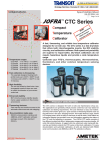
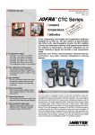
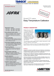
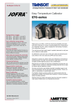
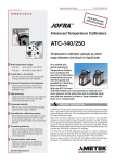
Specification Sheet
SS-CP-2281-US
temperature
CTC series
Compact
Temperature
Calibrators
Fast, timesaving, and reliable true
temperature calibrator
Temperature ranges
CTC-140 A
CTC-320 A
CTC-320 B
CTC-650 A
CTC-650 B
CTC-1200 A
-17 to 140°C / -1 to 284°F
33 to 320°C / 91 to 608°F
33 to 320°C / 91 to 608°F
33 to 650°C / 91 to 1202°F
33 to 650°C / 91 to 1202°F
300 to 1205°C / 572 to 2200°F
Fast calibration is timesaving
The specially designed heating block
profile heats up to 320°C / 608°F in just
4 minutes and to 650°C / 1202°F in only
10 minutes
High flexibility
You are not limited by fixed holes.
Inter-changeable insertion tubes are
used to match the diameter of your
sensor-under-test
Enhanced stability
MVI circuitry ensures stability despite
mains supply variations in the process
environment
Timesaving features
Fast one-key-one-function access to the
automatic switch test and auto stepping
Documentation made easy
RS232 communication and JOFRACAL
calibration software are included in the
standard delivery
Complete marine program
Part of a complete program of marine
approved temperature, pressure and signal
calibrators; including temperature sensors
See more at www.jofra.com
ISO 9001 Manufacturer
A fast, timesaving, and reliable
true temperature calibrator
designed for on-site use.
The CTC series is a fast
dry-block that offers both
interchangeable inserts,
the MVI stability circuitry,
and calibration software.
Both speed and portability
are superior to liquid baths.
Dry-block calibrators do not
require hazardous liquids
and provide a wide
temperature range.
Calibrate your RTD’s, thermocouples, thermoswitches,
thermistors, and other common temperature sensing
devices.
PRODUCT DESCRIPTION
The CTC series is designed for both on-site and maintenance shop use.
The applications are generally critical process control but can vary based on
calibration and testing requirements. The user interface is easy and intuitive.
One-key-one-function gives you quick access to timesaving features such
as the switch test or the auto-stepping function. All models feature a large,
backlit LCD display panel, which is easy-to-read even in well-lit areas. Units
feature an informative display that provides icons and information regarding
the status of the CTC and the calibration in-progress. The JOFRA CTC
series consists of six different models that differ in temperature ranges and
immersion depths. All units offer similar features. A rugged, slim-line, aluminum outer casing with die-cast top and bottom protects the CTC series
of dry-block calibrators. For easy documentation and automatic calibration,
all units are delivered with RS232 serial communication and JOFRACAL
calibration software.
Specification Sheet
SS-CP-2281-US
Fast heating and cooling
MVI - Improved temperature stability
The CTC-320 A and the CTC-650 A contain an innovative
heating block profile. This design heats up the CTC-320 A to
maximum temperature in just 4 minutes and the CTC-650 A
in only 10 minutes. The fast performance of the heating block
is due to the special profile that minimizes mass and yet, still
accepts an insertion tube with a 25 mm / 1 in. outer diameter.
This design is a balanced compromise between temperature
stability / homogeneity and rapid heating / cooling.
MVI stands for ’’Mains power Variance Immunity’’.
Unstable mains power supplies are a major contributor to onsite calibration inaccuracies. Traditional temperature calibrators
often become unstable in production environments where large
electrical motors, heating elements, and other devices are periodically cycled on or off. The cycling of supply power can cause
the temperature regulator to perform inconsistently leading to
both inaccurate readings and unstable temperatures.
The CTC series employ the MVI, thus avoiding such stability
problems. The MVI circuitry continuously monitors the supply
voltage and ensures a constant energy flow to the heating
elements.
Deep immersion depth
Easy-to-use, intuitive operation
The CTC-320 B and CTC-650 B models offer a deeper immersion depth of 200 mm / 7.9 in. If you have liquid-filled sensors or
other sensors that require a deeper immersion depth, look for
the B versions. While the units do not heat and cool as quickly
as their shorter counterparts, they offer the capability to accommodate longer sensors.
All instrument controls may be performed from the front panel.
The heat source is positioned away from the panel. This design
helps to protect the operator.
Peltier effect (CTC-140 A)
The model CTC-140 A features Peltier elements.
The main functions on the CTC series are designed with onekey-one-function logic. This means that there are no sub-menus
or difficult to remember multiple keystrokes necessary to access
primary functions. The easy-to-read, backlit display features
dedicated icons, which help in identifying instrument conditions
and operational steps.
In 1834, Jean Peltier, a French physicist found that an ’’opposite thermocouple effect’’ could be observed when an electric current was connected to a thermocouple. Heat would
be absorbed at one of the junctions and discharged at the
other junction. This effect is called the ’’PELTIER EFFECT’’.
Set temperature
The practical Peltier element (electronic heating pump) consists
of many elements of semiconductor material connected electrically in series and thermally in parallel. These thermoelectric
elements and their electrical interconnections are mounted
between two ceramic plates. The plates serve to mechanically
hold the overall structure together and to electrically insulate
the individual elements from one another.
Maximum temperature
From the setup menu, the user can select the maximum temperature limit for the calibrator. This function prevents damage
to the sensor-under-test caused by the application of excessive
temperatures. The feature also aids in reducing drift resulting
from extended periods of exposures to high temperatures. This
feature can be locked with an access code.
www.jofra.com
The ’’Up’’ and ’’Down’’ arrow keys allow the user to set the exact
temperature desired with a resolution of 0.1°.
Instrument setups
The CTC series stores the complete instrument setup,
including: engineering units, stability criteria, resolution, display
contrast, slope (ramp) rate, auto-step settings, and maximum
temperature.
Stability indicator
A bold checkmark on the display indicates that the calibrator has
reached the desired set temperature and is stable. The operator
may change the stability criteria and establish a greater sense of
security in the calibration results. A convenient countdown timer
is activated five minutes before the unit reaches stability.
Specification Sheet
SS-CP-2281-US
Automatic switch test
Simplified calibration documentation - JOFRACAL
Operators can save a lot of time using the automatic thermoswitch test function to find values for the ’’Open’’ and ’’Close’’
temperatures. Additionally, this feature displays the hysteresis
(deadband) between the two points. The feature ensures a very
high repeatability when testing thermoswitches. Simply press
the ’’SWITCH TEST’’ key to activate the function.
All CTC series calibrators are provided with the JOFRACAL calibration software. This software allows the user to customize his
or her calibration routines. The software is easy-to-use so you do
not have to be a programmer to configure your own calibration
procedures. The software features prompts, menus, and help
functions that guide you through the configuration process.
Slope rate
(Ramp)
START
SWITCH
TEST
AUTO
STEP
ESC
MENU
Auto-stepping
This feature saves manpower. The operator may stay in the
control room, or another remote location, monitoring the output
from the sensor-under-test while the ITC series calibrator is
placed in the process and automatically changes the temperature using a programmed step value and rate. Up to 9 different
temperature steps may be programmed, including the hold time
for each step.
For semi-automatic calibrations, the software also supports
liquid baths, ice points, or other dry-block heating and cooling
sources. Using the software’s ’’SCENARIO’’ function allows for
combining instruments in virtually any configuration.
4
3
2
1
The JOFRACAL calibration software supports automatic
calibration for all JOFRA dry-block calibrators equipped
with an RS232 serial data interface including the JOFRA
DTI050 digital thermometer, the JOFRA DTI-1000 digital thermometer and the JOFRA ASM Multi-scanner.
SWITCH
TEST
AUTO
STEP
ESC
MENU
START
Re-calibration/adjustments
The CTC series has a very easy and straightforward procedure
for re-calibration/adjustment. There is no need for a screwdriver
or PC software. The only thing you need is a reliable reference
thermometer.
Place the probe in the calibrator and follow the instructions on
the display. Third-party labs and calibration facilities will be
able to perform this function if a certificate from an independent
source is necessary. Of course, AMETEK can provide you with
a traceable calibration certificate from our labs when you require
a higher level of confidence.
Liquid filled sensors and switches
The tall B models with an immersion depth of 190 mm / 7.5 in
are ideal for calibration of liquid filled sensors. The specially
designed non-linear heating elements in the CTC-650 B and the
increased block mass provide a
very homogeneous temperature
throughout the block. It is essential for the quality of the calibration/test that the full lenght of
the sensing part of the sensor is
exposed to the same temperature.
Calibrate analog reading devices
or switches with very high repeatability.
Once all calibrations are completed, the data may be uploaded
to the JOFRACAL calibration software for post-processing and
printing of certificates. The calibration data collected may be
stored on the personal computer for later recall or analysis.
The JOFRACAL temperature calibration software may be donwloaded from our web-page www.jofra.com.
Please also see more about JOFRACAL calibration software in
specification sheet SS-CP-2510, which can be found at www.
jofra.com
Calibration of up to 24 sensors with JOFRA ASM
Using the JOFRA ITC series together with the ASM Advanced
Signal Multi-scanner offers a great time-saving automatic solution
to calibrate multiple temperature sensors at the same time.
The ASM series is an eight channel scanner controlled by JOFRACAL software on a PC. Up to 3 ASM units can be stacked to
calibrate up to 24 sensors at the same time. It can handle signals from 2-, 3- and
4 wire RTD’s, TC’s,
transmitters, thermisters, temperature switches and
voltage.
Please also see
more in specification sheet SS-CP2360, which can
be found at www.
jofra.com
www.jofra.com
Specification Sheet
ACCESSORIES
STANDARD DELIVERY
•
•
•
•
•
•
•
•
•
•
•
•
CTC dry-block calibrator (user specified)
Mains power cable (user specified)
Traceable certificate - temperature performance
Insert (user specified)
Tool for insertion tubes
User manual
Reference manual (English)
Test cables (1 x red, 1 x black)
RS232 cable (9-pin)
JOFRACAL calibration software
CTC-140A only: Matching insulation plug kit (3 pcs)
CTC-1200 A only: Matching Insulation plug kit (3 pcs)
Part no. Description
122832
60F174
122822
123469
124528
124414 124415 124416 124518 124519 124520
Cleaning brush, 4 mm (3/Pkg)
Cleaning brush, 6 mm (3/Pkg)
Cleaning brush, 8 mm (3/Pkg)
Insulation plug kit for CTC-140 A only (3 pcs.)
Reference sensor Ø4,5 mm x 500 mm type N for
CTC-1200 A
Insulation plug kit for CTC-1200 A (3 pcs.):
12 mm - ½ in
Insulation plug kit for CTC-1200 A(3 pcs.):
3 and 4 mm - 1/8 in
Insulation plug kit for CTC-1200 A (3 pcs.):
5 and 6 mm - 1/4 and 3/16 in
Insulation plug kit for CTC-1200 A (3 pcs.):
7, 8 and 9 mm - 5/16 in
Insulation plug kit for CTC-1200 A (3 pcs.):
10 and 11 mm - 3/8 and 7/16 in
Suspension holder for sensors for CTC-1200 A
Inserts, heat shield, and cleaning brushes
Carrying case - Option C
Always use the original inserts where material and physical
dimensions have been optimized. A drilling guide is included if
you buy undrilled inserts.
The optional protective carrying
case ensures safe transportation
and storage of the instrument and
all associated equipment.
The heat shield protects
the sensor/transmitter
under test from the heated
air.
Use the cleaning brushes
to clean the borings in your
inserts when necessary.
Insulation tube and plates - 65-F100 / 105173
Heat shield - 104216
Improve your calibration uncertainty by insulating the sensorunder-test.
An external heat shield is available and may be placed on top of
the calibrator to reduce the hot air
stream around the sensor-undertest. This is especially important
for testing thermocouples having
head-mounted transmitters with
cold-junction compensation.
Minimize the heat dissipation
from the top of the block and
through the sensor-under-test.
This insulation is important for all
dry-block calibrators without the
dual-zone heating block.
www.jofra.com
SS-CP-2281-US
Specification Sheet
SS-CP-2281-US
FUNCTIONAL SPECIFICATIONS
Mains specifications
Heating time
Voltage CTC-140/320/650/1200 115V(90-127) / 230V(180-254)
Voltage CTC-650 B.................... 115V(105-127) / 230V(210-254)
Frequency, non US deliveries.................... 50 Hz ±5, 60 Hz ±5
Frequency, US deliveries............................................60 Hz ±5
Power consumption (max.) CTC-140 A.......................... 150 VA
Power consumption (max.) CTC-320 B.........................600 VA
Power consumption (max.) CTC-1200 A....................... 650 VA
Power consumption (max.) CTC-320 A / 650 A/B........1150 VA
CTC-140 A
-17 to 23°C / 1 to 73°F................................................ 3 minutes
23 to 140°C / 73 to 284°F......................................... 15 minutes
CTC-320 A
23 to 320°C / 73 to 608°F........................................... 4 minutes
CTC-650 A
23 to 650°C / 73 to 1202°F....................................... 10 minutes
CTC-320 B
23 to 320°C / 73 to 608°F......................................... 20 minutes
CTC-650 B
23 to 650°C / 73 to 1202°F.......................................39 minutes
CTC-1200 A
23 to 1205°C / 73 to 2200°F.....................................45 minutes
Temperature range
CTC-140 A
Maximum............................................................. 140°C / 284°F
Minimum @ ambient temp. 0°C / 32°F.............. -30°C / -22°F
Minimum @ ambient temp. 23°C / 73°F.................. -17°C / 1°F
Minimum @ ambient temp. 40°C / 104°F................-2°C / 28°F
CTC-320 A/B.....................................33 to 320°C / 91 to 608°F
CTC-650 A/B..................................33 to 650°C / 91 to 1202°F
CTC-1200 A...............................300 to 1205°C / 572 to 2200°F
Resolution (user-selectable)
Selectable .......................................................... 1° or 0.1°C/°F
Stability
CTC-140 A.......................................................±0.05°C / 0.09°F
CTC-320 A/B..................................................... ±0.1°C / 0.18°F
CTC-650 A / 1200 A.......................................... ±0.1°C / 0.18°F
CTC-650 B......................................................±0.05°C / 0.09°F
Measured after the stability indicator has been on for 10 minutes.
Measuring time is 30 minutes.
Time to stability (approximate)
CTC-140 A . ............................................................... 5 minutes
CTC-320/650 A/B...................................................... 8 minutes
CTC-1200 A . ........................................................... 20 minutes
Accuracy
CTC-140 A...........................................................±0.4°C / 0.7°F
CTC-320 A/B.......................................................±0.5°C / 0.9°F
CTC-650 A........................................................±0.9°C / 1.62°F
CTC-650 B........................................................±0.6°C / 1.08°F
CTC-1200 A.........................................................±2.0°C / 3.6°F
Specification when using the internal reference. (Load 4 mm OD reference probe in the center of the insert).
Immersion depth
CTC-140 A (insulation included)..................... . 115 mm / 4.5 in
CTC-320 A / CTC-650 A / CTC-1200 A............ 110 mm / 4.3 in
CTC-320 B / CTC-650 B................................... 190 mm / 7.5 in
Cooling time
CTC-140 A
100 to 0°C / 212 to 32°F........................................... 10 minutes
0 to -15°C / 32 to 5°F................................................ 16 minutes
140 to 100°C / 284 to 212°F....................................... 2 minutes
CTC-320 A
320 to 100°C / 608 to 212°F..................................... 16 minutes
CTC-650 A
650 to 100°C / 1202 to 212°F................................... 28 minutes
CTC-320 B
320 to 100°C / 608 to 212°F.....................................22 minutes
CTC-650 B
650 to 100°C / 1202 to 212°F...................................65 minutes
CTC-1200 A
1205 to 300°C / 2200 to 572°F.............................. 120 minutes
Switch input (dry contact)
Test voltage ................................................... Maximum 5 VDC
Test current .................................................. Maximum 2.5 mA
JOFRACAL software
Minimum hardware requirements for JOFRACAL calibration
software.
•
•
•
•
•
•
INTELTM 486 processor
(PENTIUMTM 800 MHz recommended)
32 MB RAM (64 MB recommended)
80 MB free disk space on hard disk prior to installation
Standard VGA (800 x 600, 16 colors) compatible screen
(1024 x 786, 256 colors recommended)
CD-ROM drive for installation of the program
1 free RS232 serial port
Well diameter
CTC-140....................................................... . 19,2 mm / 0.76 in
CTC-320 / CTC-650............................................ 26 mm / 1.0 in
CTC-1200............................................................ 27 mm / 1.6 in
www.jofra.com
Specification Sheet
KEY FEATURES
SS-CP-2281-US
PHYSICAL SPECIFICATIONS
Automatic switch test
Instrument dimensions
Finds switching temp. .........................Open, close, hysteresis
Slope rate, programmable ...............................0.1 to 9.9 °C/°F
CTC-140 A / CTC-320 A / CTC-650 A
L x W x H:................... 241 x 139 x 325 mm / 9.5 x 5.5 x 12.8 in
CTC-320 B / CTC-650 B / CTC-1200 A
L x W x H:................... 241 x 139 x 408 mm / 9.5 x 5.5 x 16.1 in
Auto stepping
Programmable...................................................... Up to 9 steps
Dwell time on each step.....................................Programmable
Enhanced stability
Unstable mains protection....................................MVI Circuitry
Clear stability indication......................................Yes, in display
Multi-information display
Stability indicator..............................................Bold checkmark
Countdown timer before stable.................................. 4 minutes
Temperature............................ SET and READ simultaneously
Alphanumeric messages......................................................Yes
Calibration status icons........................................................Yes
Training mode (heating/cooling block disabled)
Simulation of all functions....................................................Yes
Simulating heating and cooling...........Approx. 100° per minute
Service facilities
Adjustment of the unit from the keypad...............................Yes
Self explaining guide in display............................................Yes
Other information................................. Displays serial number,
...................... software revision level, and last calibration date
Setup facilities
Stability criteria...............................................Extra time before
...................................................... ’’stable indication’’ is shown
Display resolution................................................ 0.1° or 1°C/°F
Temperature units.........................................................°C or °F
Slope rate...................................................... 0.1 to 9.9°/minute
Maximum temperature.......................... Any value within range
Miscellaneous
Serial data interface ..................................RS232 (9-pin Male)
Operating temperature.......................... 0 to 40°C / 32 to 104°F
Storage temperature.......................... -20 to 50°C / -4 to 122°F
Humidity ............................................................... 0 to 90% RH
Protection class . .............................................................. IP-10
DNV Marine Approval, Certificate no............................ A-9557
Instrument weight
CTC-140 A / CTC-320 B........................................ 7 kg / 15.5 lb
CTC-320 A............................................................... 5 kg / 11 lb
CTC-650 A............................................................... 6 kg / 13 lb
CTC-650 B.......................................................... 10.5 kg / 23 lb
CTC-1200 A......................................................... 12 kg / 26.5 lb
Insert dimensions
CTC-140A outer diameter.............................. 19,1 mm / 0.75 in
CTC-140A inner diameter............................... 15,0 mm / 0.59 in
CTC-140A lenght...............................................100 mm / 3.9 in
CTC-320 / CTC-650 A outer diameter........... 25,7 mm / 1.01 in
CTC-320 / CTC-650 A inner diameter........... 21,5 mm / 0.85 in
CTC-320 / CTC-650 A lenght .......................... 120 mm / 4.7 in
CTC-320 / CTC-650 B outer diameter........... 25,7 mm / 1.01 in
CTC-320 / CTC-650 B inner diameter........... 21,5 mm / 0.85 in
CTC-320 / CTC-650 B lenght .......................... 200 mm / 7.9 in
CTC-1200 A outer diameter..............................25 mm / 0.98 in
CTC-1200 A inner diameter................................. 22 mm / 1.6 in
CTC-1200 A lenght............................................ 155 mm / 6.1 in
Weight of non-drilled insert (approximate)
CTC-140 A.............................................................. 75 g / 2.6 oz
CTC-320 A........................................................... 170 g / 5.8 oz
CTC-650 A..........................................................510 g / 17.8 oz
CTC-320 B...........................................................280 g / 9.8 oz
CTC-650 B.........................................................860 g / 30.3 oz
CTC-1200 A........................................................460 g / 16.3 oz
Shipping (including optional carrying case)
CTC-140 A.........................................................12.5 kg / 27.6 lb
CTC-320 A............................................................. 11 kg / 24 lb
CTC-650 A............................................................. 12 kg / 27 lb
CTC-320 B.......................................................... 13.5 kg / 21 lb
CTC-650 B............................................................. 17 kg / 37 lb
CTC-1200 A............................................................ 18 kg / 39 lb
Size L x W x H:..........507 x 232 x 415 mm / 19.9 x 9.1 x 16.3 in
Shipping (without carrying case)
CTC-140 A.............................................................. 10 kg / 22 lb
CTC-320 A.............................................................8 kg / 17.5 lb
CTC-650 A............................................................. 9.5 kg /21 lb
A Size L x W x H:... 465 x 255 x 470 mm / 18.3 x 10.0 x 18.5 in
CTC-320 B............................................................. 11 kg / 24 lb
CTC-650 B............................................................. 14 kg / 26 lb
CTC-1200 A............................................................ 15 kg / 32 lb
B Size L x W x H:... 465 x 255 x 470 mm / 18.3 x 10.0 x 18.5 in
Shipping (carrying case only)
Weight: ................................................................. 5.0 kg / 11 lb
Size L x W x H:..........507 x 232 x 415 mm / 19.9 x 9.1 x 16.3 in
www.jofra.com
Specification Sheet
SS-CP-2281-US
INSERTS FOR CTC SERIES
Inserts for CTC-140 A and CTC-320 A/B are made of aluminum. Inserts for CTC-650 A/B are made of
brass. Inserts for CTC-1200 A are made of high-temperature steel alloy.
All specifications on hole sizes are referring to the outer diameter of the sensor-under-test.
The correct clearance size is applied in all predrilled inserts.
Undrilled inserts
(CTC-140 A)
Inserts, undrilled
Instruments
CTC-140 A 2
CTC-320 A
CTC-650 A
CTC-320 B
CTC-650 B
CTC-1200 A 4
5-pack, undrilled
inserts
60F448
100175
100194
60F356
60F420
124403
Undrilled
insulation plug
123937
N/A
N/A
N/A
N/A
see below 4
Inserts
Undrilled inserts
Spare part no. for predrilled inserts - metric (mm)
Instruments
(CTC-320 / 650 A/B)
Insert code 1
CTC-140 A 2
CTC-320 A
CTC-650 A
CTC-320 B
CTC-650 B
CTC-1200 A 4
3 mm
003
123428
123436
123444
N/A
N/A
124503
4 mm
004
60F451
100177
100196
60F359
60F423
124406
5 mm
005
123429
123437
123445
123452
123460
124504
6 mm
006
60F453
100179
100198
60F361
60F425
124407
7 mm
007
123430
123438
122516
123453
123461
124505
8 mm
008
105185
100182
100201
105190
105195
124506
9 mm
009
105186
100183
100202
105191
105196
124507
Undrilled inserts
10 mm
010
105187
100185
105188
105192
105197
124508
(CTC-1200 A)
11 mm
011
123431
100188
100204
105193
105198
124509
12 mm
012
123432
100186
100206
105194
105199
124510
13 mm
013
123433
60F339
105189
123454
123462
N/A
14 mm
014
N/A
100190
100208
123455
123463
N/A
15 mm
015
N/A
100191
100209
123456
123464
N/A
16 mm
016
N/A
123439
123446
123457
123465
N/A
18 mm
018
N/A
123440
122517
123458
123466
N/A
Multi-hole type 1
20 mm
020
N/A
123441
122518
123459
123467
N/A
(CTC-140 A)
124679
124681
124685
124683
124687
124689
123479 3
123475
123476
N/A
N/A
N/A
Probe diameter
Package of the
above inserts
Multi-hole type 1
M01
4,5 mm
3 mm
4 mm
6 mm
5 mm
3/16 in
Spare part no. for predrilled inserts - imperial (inch)
Instruments
1/8 in
1/4 in
Insert code 1
CTC-140 A 2
CTC-320 A
CTC-650 A
CTC-320 B
CTC-650 B
CTC-1200 A 4
1/8 in
125
60F450
100176
100195
60F358
60F422
124511
Multi-hole type 2
3/16 in
187
60F452
100178
100197
60F360
60F424
124512
(CTC-140 A)
1/4 in
250
60F454
100180
100199
60F362
60F426
124404
5/16 in
312
60F456
100181
100200
60F364
60F428
124513
3/8 in
375
60F458
100184
100203
60F366
60F430
124514
7/16 in
437
60F460
100187
100205
60F368
60F432
124515
1/2 in
500
60F462
100189
100207
60F370
60F434
124405
9/16 in
562
60F464
60F344
60F408
60F372
60F436
N/A
5/8 in
625
60F466
100192
100210
60F374
60F438
N/A
11/16 in
688
N/A
60F348
60F412
60F376
60F440
N/A
3/4 in
750
N/A
100193
100211
60F378
60F442
N/A
Multi-hole type 1
13/16 in
813
N/A
60F352
60F416
105184
60F444
N/A
7/8 in
875
N/A
60F354
60F418
60F377
60F446
N/A
(CTC-320 A / 650 A)
124680
124682
124686
124684
124688
124690
123480 3
123477
123478
N/A
N/A
N/A
Probe diameter
Package of the
above inserts
Multi-hole type 2
M02
Note 1:Use the insert code, when ordered as the standard insert together with a new calibrator.
Note 2: CTC-140 A only: Remember to use matching insulation plugs (see accessories).
Note 3:CTC-140 A only: All multi-hole inserts are delivered with a matching insulation plug.
Note 4:CTC-1200 A only: Remember to order matching insulation plugs (see accessories).
9 mm
3 mm
6 mm
4 mm
5 mm
3/8 in
1/8 in
3/16 in
1/4 in
Multi-hole type 2
(CTC-320 A / 650 A)
www.jofra.com
ORDERING INFORMATION
Order number
Description
CTC140A
CTC320A
CTC650A
CTC320B
CTC650B
CTC1200A
Base model number
CTC-140 A, -17 to 140°C / -1 to 284°F
CTC-320 A, 33 to 320°C / 91 to 608°F
CTC-650 A, 33 to 650°C / 91 to 1202°F
CTC-320 B, 33 to 320°C / 91 to 608°F
CTC-650 B, 33 to 650°C / 91 to 1202°F
CTC-1200 A, 300 to 1205°C / 572 to 2200°F
115
230
Power supply (US deliveries 60 Hz only)
115VAC
230VAC
A
B
C
D
E
F
G
H
I
Mains power cable type
European, 230 V,
USA/CANADA, 115 V
UK, 240 V
South Africa, 220 V
Italy, 220 V
Australia, 240 V
Denmark, 230 V
Switzerland, 220 V
Israel, 230 V
XXX
Insert type and size
1 x Insert for dry-block configuration
(please see the previous insert pages for the right insert codes)
F
G
H
H
Calibration certificate
NLP Traceable temperature certificate
(standard for Europe, Asia, Australia and Africa)
NIST traceable temperature certificate
(standard for Western Hemisphere)
Accredited certificate with 5 std. points
(except CTC-1200 A)
Accredited certificate with 4 std. points
(for CTC-1200 A)
Options
C Carrying case
X No option used
CTC650A230AM01FX
Sample order number
JOFRA CTC-650 A dry-block, 230 VAC power with European power cord and insert:
Pre-drilled multi-hole type 1 (1 x 3 mm, 1 x 4 mm, 1 x 5 mm, 1 x 6 mm, 1 x 9 mm), and NLP traceable certificate.
AMETEK Calibration Instruments
offers a complete range of calibration
equipment for temperature, pressure, and
signal - including calibration software.
JOFRA Temperature Calibrators
Portable precision thermometer.
Dry-block and liquid bath calibrators:
4 series, with more than 20 models - featuring
speed, portability, accuracy and advanced
documenting functions with JOFRACAL
temperature calibration software.
JOFRA Pressure Calibrators
Convenient electronic systems ranging from
-1 to 700 bar (25 inHg to 10,000 psi) - multiple
choices of pressure ranges, pumps and
accuracies, fully temperature-compensated
for problem-free and accurate field use.
JOFRA Signal Calibrators
Process signal measurement and simulation for
easy control loop calibration and measurement
tasks - from handheld field instruments for
multi or single signals to laboratory reference
level bench top instruments.
JOFRA / JF Marine Calibrators
A complete range of calibration equipment
for temperature, pressure and signal, approved
for marine use.
FP Temperature Sensors
A complete range of temperature sensors
for industrial and marine use.
...because calibration is
a matter of confidence
AMETEK Calibration Instruments is one of the world’s leading manufacturers and developers of calibration
instruments for temperature, pressure and process signals as well as for temperature sensors both from a
commercial and a technological point of view.
Headquarter:
AMETEK Denmark A/S
(Sales, Europe and the Middle East)
Gydevang 32-34 • 3450 Allerød • Denmark
Tel: +45 4816 8000 • [email protected]
www.ametekcalibration.com
www.jofra.com
Information within this document is subject to change without notice.
©2005, by AMETEK, Inc., www.ametek.com. All rights reserved.
Pub code SS-CP-2281-US Issue 0610
www.jofra.com
Sales offices:
AMETEK T&CI - Americas (Sales, The Americas)
Tel: +1 518 689 0222 • [email protected]
AMETEK Singapore Pte. Ltd. (Sales, Asia)
Tel: +65 6 484 2388 • [email protected]
AMETEK Inc. Beijing Rep. Office (Sales, China only)
Tel: +86 10 8526 2111 • [email protected]
AMETEK GmbH (Sales, Germany only)
Tel: +49 2159 91360 • [email protected]
AMETEK Lloyd Instruments (Sales, UK only)
Tel: +44 (0) 1489 486 404 • [email protected]