1
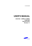
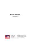
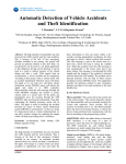
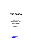
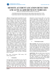
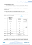
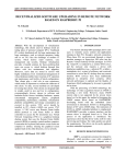
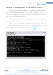
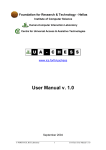
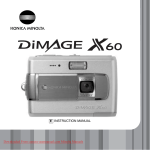
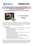
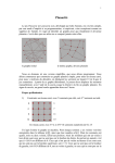
INTERNATIONAL JOURNAL OF PROFESSIONAL ENGINEERING STUDIES Volume I/Issue 2/DEC 2013 Design of S3C2440 Based Embedded Media Player D.Kondal Reddy 1, A.Chakradhar 2 1 M.Tech Student, Dept of ECE, Jayamukhi Institute of Technological Sciences, Narasampet, Warangal Dist, a.p, India 2 Assistant Professor, Dept of ECE, Jayamukhi Institute of Technological Sciences, Narasampet, Warangal Dist, a.p, India Abstract: The following paper proposes a method of understanding and implementing a light weighted media player using SDL based FFMPEG media player library on a S3C2440 based SOC board running on ARM9 hardware with LINUX as the target OS. The most notable parts of FFMPEG are libavcode, an audio/video codec, libavformat, an audio/video container mux and demux library, and the FFMPEG command line program for transcoding multimedia files. In the software the configured and optimized Linux operating system to the S3c2440, then transplant the critical core library SDL_FFMPEG to the S3C2440 after cross-compiled. The whole system realized playing the video and picture files smoothly in the embedded platform we select. An embedded media player is a light weighted media player, is used to play different formats of audio/video and picture frames. It is a kind of popular entertainment consumer electronic product and plays important role in people’s life. Nowadays, People especially need it when they are in tourism, outdoor activities and travel. Keywords-S3C2440; SDL; SDL_FFMPEG; Linux I. SDL_FFMPEG library to decode the video files. II. All the personal computer based media players like VLC player ,windows media player occupies high memory foot print we cannot use it to run as part of devices which are resource constraint. These players use processing of graphical user interface which decreases the performance of processor. Current media players do not convert one format to another and also do not support editing of audio\video. VLC media player can be long and complex for new developers. Code is written by expert C hackers and sometimes it is very hard to understand. Another key feature of VLC is that decoding and playing are asynchronous. Decoding is done by a decoder thread, playing is done by audio output or video output thread. The design goal is to ensure that an audio or video frame is played exactly at the right time, without blocking any of the decoder threads. VLC has a core and a lot of modules (between 200 and 400 depending on the build). VLC cannot do much without modules, since modules provide most of the functionalities. Introduction III. Nowadays, a Media Player is a kind of popular entertainment consumer electronic product and plays important role in people’s life. People especially need it when they are in tourism, outdoor activities and travel. Many manufacturers make it their market target for its high popularizing rate year by year and its increasing market. Anyone who has the largest cost advantage and the best quality will gain advantage in the competition. Based on this, we use S3C2440 as core processor, and extend the memory and external memory on this base, at same time we can extend SD card, USB, LCD, audio interface. In the software we can transplant, configured and optimized Linux operating system to the S3c2440, use SDL library to design the player’s interface, use IJPRES Existing system Design of proposed hardware system S3C2440Amicrocontroller: SAMSUNG's S3C2440A 16/32-bit RISC microprocessor. SAMSUNG’s S3C2440A is designed to provide hand-held devices and general applications with lowpower, and high-performance microcontroller solution in small die size. NAND Flash Memory: K9K8G08U0A a kind of 1GB Nand Flash as external memory. Nand Flash is used for data storing so that operating system, Boot Loader and other application software can be placed here. 159 INTERNATIONAL JOURNAL OF PROFESSIONAL ENGINEERING STUDIES Volume I/Issue 2/DEC 2013 LCD displays utilize two sheets of polarizing material with a liquid crystal solution between them. Hence we can see from Figure 1, Nand Flash is used for data storing so that operating system, Boot Loader and other application software can be placed here. SDRAM is used as dynamic memory when system works. SD card and U-disk is used as an external expansion memory to store files that we needed. Touch screen is used to display and choose menu. Audio interface is used to play audio information only. UART port is used to interact with developers when in the development stage, but it is useless when the product is finished, so it can be removed at last. IV. Figure.1. System Hardware Structure SDRAM: The 64Mb SDRAM is a high-speed CMOS, dynamic random-access memory containing 912 bits. It is internally configured as a quad-bank DRAM with synchronous interface. UART interface: A UART is the microchip with programming that controls a computer's interface to its attached serial devices. Specifically, it provides the computer with the RS-232 DTE interface so that it can "talk" to and exchange data with modems and other serial devices. USB Host Interface: The USB Host library is an embedded USB stack supporting USB MSC (Mass Storage Class) and HID (Human Interface Device) classes. It has been designed to be high-performance while using as little memory as possible. USB Device Interface: The USB Device Interface uses standard device driver’s class that is available in Windows PC’s. No Windows host driver development is required. The USB Device interface uses a generic software layer with the help of using RTX Kernel features. Audio interface: Professional soundcards are special soundcards optimized for low-latency multichannel sound recording and playback, including studio-grade fidelity. Their drivers usually follow the Audio Stream Input Output protocol for use with professional sound engineering and music software, although ASIO drivers are also available for a range of consumer-grade soundcards. LCD Display Liquid crystal display (LCD) is a type of display used in digital watches and many portable computers. IJPRES Board Hardware Resources Features: S3C2440Amicrocontroller: The S3C2440 is developed with ARM920T core, 0.13um CMOS standard cells and a memory compiler. Its low power, simple, elegant and fully static design is particularly suitable for cost- and power-sensitive applications. It adopts a new bus architecture known as Advanced Micro controller Bus Architecture. The s3c2440 offers outstanding features with its CPU, a 16/32-bit Arm920T RISC processor designed by Advanced RISC Machines, Ltd. The ARM920T implements MMU, AMBA BUS, and Harvard cache architecture with separate 16KB instruction and 16KB data caches, each with an 8-word line length. By providing a complete set of common system peripherals, the S3c2440 minimize the system costs and eliminates the need to configure additional components. The integrated on-chip functions included 1.28V,1.8V,5V,3.3V to external I/O microcontroller with 16KB I-Cache/16KB D Cache/MMU and has external memory controller (SDRAM Control and Chip Select logic).The LCD controller (up to 4K color STN and 256K color TFT) with LCD-dedicated DMA and 4ch DMA controllers with external request pins,3-ch UARTs (IrDA1.0, 64-Byte Tx FIFO, and 64-Byte Rx FIFO),2-ch SPls , IIC bus interface (multi-master support),IIS Audio CODEC interface,AC’97 CODEC interface,SD Host interface version 1.0 & MMC Protocol, compatible,2-ch USB Host controller / 1-ch USB Device controller,4-ch PWM. timers / 1-ch Internal timer / Watch Dog Timer,8-ch 10-bit ADC and Touch screen interface ,RTC with calendar function, Camera interface (Max. 4096 x 4096 pixels input support. 2048 x 2048 pixel input support for scaling),130 General Purpose I/O ports / 24-ch external interrupt source, Power control modes are Normal, Slow, Idle and Sleep mode. The S3C2440A offers outstanding features with its CPU 160 INTERNATIONAL JOURNAL OF PROFESSIONAL ENGINEERING STUDIES Volume I/Issue 2/DEC 2013 core, a 16/32-bit ARM920T RISC processor designed by Advanced RISC Machines, Ltd. NAND Flash Controller NOR flash memory gets high in price while an SDRAM and a NAND flash memory is comparatively economical, motivating some users to execute the boot code on a NAND flash and execute the main code on an SDRAM. S3C2440A boot code can be executed on an external NAND flash memory. In order to support NAND flash boot loader, the S3C2440A is equipped with an internal SRAM buffer called ‘Steppingstone’. When booting, the first 4 Kbytes of the NAND flash memory will be loaded into Steppingstone and the boot code loaded into Steppingstone will be executed. Generally, the boot code will copy NAND flash content to SDRAM. Using hardware ECC, the NAND flash data validity will be checked. Upon the completion of the copy, the main program will be executed on the SDRAM. The NAND Flash Controller supports direct access interface with the NAND flash memory. Features of NAND Flash Memory: 1. Auto boot: The boot code is transferred into 4kbytes Steppingstone during reset. After the transfer, the boot code will be executed on the Steppingstone. 2. NAND Flash memory I/F: Support 256Words, 512Bytes, 1KWords and 2KBytes. 3. Software mode: The User can directly access NAND flash memory, for example this feature can be used in read/erase/program NAND flash memory. 4. Interface: 8 / 16-bit NAND flash memory interface bus. 5. Hardware ECC generation, indication (Software correction). detection and 6. SFR I/F: Support Little Endian Mode, Byte/half word/word access to Data and ECC Data register, and Word access to other registers. SDRAM The 64Mb SDRAM is a high-speed CMOS, dynamic random-access memory containing 912 bits. It is internally configured as a quad-bank DRAM with a synchronous interface (all signals are registered on the positive edge of the clock signal, CLK). Each of the x4’s 134,217,728-bit banks is organized as 8,192 rows by 4,096 columns by 4 bits. Each of the x8’s 134,217,728-bit banks is organized as 8,192 rows by 2,048 columns by 8 bits. Each of the x16’s 134,217,728-bit banks is organized as 8,192 rows by 1,024 columns by 16 bits. Read and write accesses to IJPRES the SDRAM are burst oriented; accesses start at a selected location and continue for a programmed number of locations in a programmed sequence. Accesses begin with the registration of an ACTIVE command, which is then followed by a READ or WRITE command. The address bits registered coincident with the ACTIVE command are used to select the bank and row to be accessed (BA0, BA1 select the bank; A0–A12 select the row). The address bits registered coincide with the read or write command is used to select the starting column location for the burst access. The SDRAM provides for programmable READ or WRITE burst lengths (BL) of 1, 2, 4, or 8 locations, or the full page, with a burst terminate option. An auto precharge function may be enabled to provide a self-timed row precharge that is initiated at the end of the burst sequence. Mode Register The mode register is used to define the specific mode of operation of the SDRAM. This definition includes the selection of BL, a burst type, CL, an operating mode, and a write burst mode, as shown in Figure 5 on page 14. The mode register is programmed via the Load Mode Register command and will retain the stored information until it is programmed again or the device loses power. Mode register bits M0–M2 specify BL, M3 specifies the type of burst (sequential or interleaved), M4–M6 specify CL, M7 and M8 specify the operating mode, M9 specifies the write burst mode, and M10 and M11 are reserved for future use. Address A12 (M12) is undefined but should be driven low during loading of the mode register. The mode register must be loaded when all banks are idle, and the controller must wait the specified time before initiating the subsequent operation. Violating either of these requirements will result in unspecified operation. SD Card Secure Digital (SD) is a non-volatile memory card format developed by the SD Card Association (SDA) for use in portable devices. The SD technology is used by more than 400 brands across dozens of product categories and more than 8,000 models. SD comprises several families of cards the original Standard-Capacity (SDSC) card, a High-Capacity card family an extended-Capacity (SDXC) card family and the SDIO family with input/output functions rather than just data storage. SD also comprises three different factors: the original size, the "mini" size, and the "micro" size (see illustration). Electrically passive adaptors allow the use of a smaller card in a host device built to hold a 161 INTERNATIONAL JOURNAL OF PROFESSIONAL ENGINEERING STUDIES larger card. There are many combinations of form factors and device families. Host devices that comply with newer versions of the specification provide backward compatibility and accept older SD cards, but older host devices do not recognize newer cards. The SDA uses several trademarked logos to enforce compliance with its specifications and assure users compatibility. This article explains several factors that can prevent the use of a newer SD card. Volume I/Issue 2/DEC 2013 always 0 and stop bit is 1.It changes the signal per second. The block diagram for the UART with its I/O ports and three main blocks is shown. The block diagram shows the different components. The D_XS, XCS, DATA, XWR, XRD inputs are synchronized with the clock by their respective synchronizing blocks each of which register the signals twice. Figure.2. SD Card interface UART interface A UART is the microchip with programming that controls a computer's interface to its attached serial devices. Specifically, it provides the computer with the RS-232 interface so that it can "talk" to and exchange data with modems and other serial devices. Figure.3. UART Block Diagram UART Overview: As part of this interface, the UART also perform the following operations, 1) Converts the bytes it receives from the computer along parallel circuits into a single serial bit stream for outbound transmission 2) Adds a parity bit (if it's been selected) on outbound and stop delineators on outbound and strips them from inbound transmissions 3) Handles interrupt s from the keyboard and mouse (which are serial devices with special ports 4) May handle other kinds of interrupt and device management that require coordinating the computer's speed of operation with device speeds Universal Asynchronous Receiver Transmitter. It takes parallel data and transmits serially. It receives serial data and converts to parallel. The extra parity bit is used for simple error checking. The start bit is IJPRES The S3C2440A Universal Asynchronous Receiver and Transmitter (UART) provide three independent asynchronous serial I/O (SIO) ports, each of which can operate in Interrupt-based or DMA-based mode. In other words, the UART can generate an interrupt or a DMA request to transfer data between CPU and the UART. The UART can support bit rates up to 115.2K bps using system clock. If an external device provides the UART with UEXTCLK, then the UART can operate at higher speed. Each UART channel contains two 64-byte FIFOs for receiver and transmitter. The S3C2440A UART includes programmable baud rates, infrared (IR) transmit/receive, one or two stop bit insertion,5-bit, 6-bit, 7-bit or 8-bit data width and parity checking. Each UART contains a baud-rate generator, transmitter, receiver and a control unit, as The baud-rate generator can be clocked by 162 INTERNATIONAL JOURNAL OF PROFESSIONAL ENGINEERING STUDIES Volume I/Issue 2/DEC 2013 PCLK, FCLK/n or UEXTCLK (external input clock). The transmitter and the receiver contain 64byte FIFOs and data shifters. Data is written FIFO and then copied to the transmit shifter before being transmitted. The data is then shifted out by the transmit data pin (TxDn). Meanwhile, received data is shifted from the receive data pin (RxDn), and then copied to FIFO from the shifter. USB Host Interface The USB Host library is an embedded USB stack supporting USB MSC (Mass Storage Class) and HID (Human Interface Device) classes. It has been designed to be high-performance while using as little memory as possible. The USB Host library includes examples which demonstrate using USB mass storage devices together with a flash file System, and using an external HID input devices. Custom Host controller driver for STM32F105/7 (connectivity line) devices USB 1.1 Low Speed (1.5Mbit/s) and Full Speed (12Mbit/s) Common USB Device Class support Human Interface Devices (HID) Mass Storage Class (MSC) High-speed (670KB/sec) and small codesize (~6KB) Integrated with other MDK-Professional components MSC works with Flash File System to support USB Flash drive and SD/SDHC/MMC card storage devices USB Host works with the RTX Real-Time Operating System USB Device Interface MDK-Professional provides USB Device and USB Host support for embedded systems. The USB Device Interface uses standard device driver classes that are available with all Windows PCs. No Windows host driver development is required. The USB Device interface uses a generic software layer using RTX Kernel features. Figure.4. Block diagram of USB Host Interface The USB Host Interface is provided in binary form as part of MDK-Professional. It is not included with other MDK-ARM Editions. Figure.5. Block diagram of USB Device Interface Features Features Abstraction layer allows a standard API to be used for different USB Host controllers USB Host controller support Generic Open Host Controller Interface (OHCI) Low level driver support for NXP LPC17xx/23xx/24xx devices IJPRES USB Hardware layer and event handler (hardware specific) Generic USB core supporting USB 1.1 and 2.0 Low Speed (1.5Mbit/s), Full Speed (12Mbit/s), & High-Speed (480Mbit/s) Common USB Device Class support Human Interface Devices (HID), Mass Storage Class (MSC), 163 INTERNATIONAL JOURNAL OF PROFESSIONAL ENGINEERING STUDIES Volume I/Issue 2/DEC 2013 Audio Device (ADC), Communication Device (CDC), & Composite Device Integrated with other MDKProfessional components MSC works with Flash File System to support SD/MMC card storage Works with RTX Real-Time Kernel V. Operating System Customization Linux is a UNIX-based operating system originally developed as for Intel-compatible PC's. It is now available for most types of hardware platforms, ranging from PDAs (and according to some reports, a wristwatch) to mainframes. Linux is a "modern operating system", meaning it has such features as virtual memory, memory protection, and preemptive multitasking. Linux is built and supported by a large international community of developers and users dedicated to free, open-source software. This community sees Linux as an alternative to such proprietary systems as Windows and Solaris and as a platform for alternatives to such proprietary applications as MS Office, Internet Explorer, and Outlook. However, Linux is a huge operating system before we optimize it, we do not need its full function, so it can be cut and optimized. We can remove some function that we don’t need, such as network, power management, wireless communication, hard disk, etc., and just retain some useful function. We can enter the command (make menu config ARCH=arm CROSS_ COMPILE=armlinux-,) in the root directory of the kernel to remove and configurate the Linux’s kernel. This is a graphical interface, so it is easy to choose. The basic steps to customize the operating system shown in Figure6: Media Player’s Core Design: The core of media player is how to encode and decode the video and audio files, then to realize the synchronization between the audio stream and video stream. There is a powerful library called FFMPEG, it provide a complete solution to the audio and video stream. The core of FFMPEG is a library called libavcode which has a big advantage in encoding and decoding audio and video files. However FFMPEG is very difficult to understand and use, especially for the beginners. SDL_FFMPEG library is built on the base of FFMPEG, its core component is still the FFMPEG’s library called libavcode. But SDL_FFMPEG packaged for the FFMPEG and masked some difficulty details. IJPRES Figure.6. Linux System develop steps Then SDL_FFMPEG packaged multiple functions into some interfaces. So that the users needn’t know how to use the FFMPEG, only use the functions provided by the SDL_FFMPEG. We can call SDL_ffmpegFile* SDL_ffmpegOpen(const char* filename) to open the video files, also can call SDL_ffmpegAddVideoFrame()to add a frame of SDL_ffmpegFrame. Media Player’s Software Interface Design SDL (Simple Direct Media Layer) is a cross-platform multimedia library. It is mainly to provide a unified programming interface for cross-platform, also for application software development, especially provide convenient for code transplant. SDL is written in C, provides functions to user by library, and also provides a large number of other programming language interfaces. A very important feature of SDL is its open source, users can get the source code through SDL’s home page, and can use it freely only follow the license of GNU LGPL version 2. SDL is also very simple to use, it includes eight subsystems, such as sound, event handler, timer, video, etc. The user must call the function of 164 INTERNATIONAL JOURNAL OF PROFESSIONAL ENGINEERING STUDIES SDL_Init () to initialize the system, user can also initialize the system through setting the parameters of SDL_Init (), such as choose the audio interface by calling SDL_Init (SDL_INIT_AUDIO). In this paper’s software we need multiple subsystems, so we call the function SDL_Init(SDL_INIT_AUDIO| SDL_INIT_VIDEO| SDL_INIT_TIMER)to initialize. Specific to the different equipment, SDL provides corresponding functions, such as we can use SDL_ Open Audio() to access the sound information through sound equipment. And its parameters can be used to set frequency, sampling format. We also can call SDL_Get Video Surface () to get a pointer to the picture which currently displayed on the screen, and we can call SDL_SetVideoMode() to set the screen’s size if it is necessary. The purpose of this paper is to design a media player, so we take a lot of time to research the video subsystem. The SDL regards the video area which we want to show as a unity video buffer, anything that we operate in the screen can be mapped to the corresponding video buffer. Actually video buffer can be either a physical memory or a video graphic device memory, which one selected to be used can be specified when initializing the video system. In this paper, we select the physical memory as a buffer, so we can call SDL_Surface *SDL_SetVideoMode (int width, int height, int bpp, Uint32 flags) to set the buffer, and the parameter flags we select SDL_SWSURFACE. As for the interface of the software we can draw it on the paper first, then divide it into small pieces, and draw the every piece on the drawing software, such as button, line, a variety of decorative things, etc. The function of SDL is just like a sketchpad, we can stick up the elements on it. VI. Volume I/Issue 2/DEC 2013 [2] Karlm Yaghmour, “Building Embedded Linux System”, USA: O’Reilly, 2003. [3] Bob Pendleton. “Game Programming with the Simple DirectMedia Layer” Specialized Systems Consultants, 2003, 110:1. [4] Robert Love, “Linux Kernel Development(Third Edition)”,China Machine Press, 2011. [5] Sam Lantinga: http://sdldoc.csn.ul.ie/, 2001.9. [6] SDL’s home http://www.libsdl.org/index.php. page: [7] SDL_FFMPEG’s home page:http://www.arjanhouben.nl/SDL_ffmpeg/. angerlee,“SDL to play video”, [8] http://www.flycode.org/forum.php?mod=viewthr ead&t=222=id&page= Mr. Kondal Reddy Donakonda pursuing his M. Tech in Embedded Systems from Jayamukhi Institute of Technological Sceinces, Narsampet(Moqdumpooram), Warangal. Mr. A.CHAKRADHAR, his Qualification is M.tech,currently working as an Associate Professor, in the Department of Electronics and communication Engineering, Jayamukhi Institute of Technological Sceinces, Narsampet(Moqdumpooram), Warangal,Andrapradesh, India. CONCLUSION Finally the expected play effect of video and picture files can be achieved after software and hardware debugging. Actual result shows that this system has a lot of advantages such as simple structure, small size, and low power consumption, low cost, stable. Therefore we have enough reasons to believe that this product has a broad market prospect after making series of follow-up comprehensive development in current fierce competition market. REFERENCES [1] SAMSUNG, “S3C2440A 32-BIT CMOS MICROCONTROLLER USER'S MANUAL Revision 1”.2004 Samsung Electronics. IJPRES 165