1
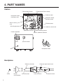
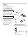
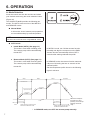
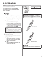
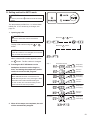
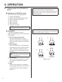
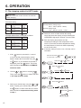
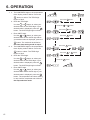
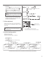
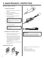
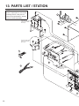
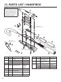
® SMD Rework Station with Vacuum Pickup Instruction Manual l Thank you for purchasing the HAKKO FR-803B SMD Rework Station. This unit features: lDigital control and display of time and temperature lDisplay of air-flow rate lManual and automatic modes lBuilt-in vacuum pickup Please read this manual before operating the HAKKO FR-803B. Keep this manual readily accessible for reference. l TABLE OF CONTENTS 1. PACKING LIST…………………………………………… 1 2. SPECIFICATIONS………………………………………… 1 3. WARNINGS, CAUTIONS, AND NOTES……………… 2 4. PART NAMES……………………………………………… 3 5. PREPARATION: ASSEMBLY AND ELECTRICAL CONNECTION……… 5 6. OPERATION……………………………………………… 8 7. PARAMETERS………………………………………… 17 8. OFFSET SETTING METHOD………………………… 18 9. MAINTENANCE / INSPECTION……………………… 19 10. ERRO MESSAGE…………………………………… 20 11. TROUBLESHOOTING……………………………… 20 12. OPTINAL PARTS……………………………………… 21 13. PARTS LIST / STATION……………………………… 23 13. PARTS LIST / HANDPIECE………………………… 25 14. WIRING DIAGRAM…………………………………… 26 1. PACKING LIST Check the contents of the HAKKO FR-803B package and confirm that all the items listed below are included. HAKKO FR-803B station.......................................... 1 Power cord............................................................... 1 Handpiece holder..................................................... 1 Pads (ø3 mm (0.12 in.), ø5 mm (0.20 in.), ø7.6 mm (0.3 in.))......2 each Vacuum pipe control knob (L)................................... 1 Control card.............................................................. 1 Connecting cord....................................................... 1 Instruction manual.................................................... 1 * This product does not include a nozzle. A large selection of nozzles are available for the HAKKO FR-803B. Select the nozzle or nozzles suitable for the work to be performed. Power cord Control card 2 for each pad Vacuum pipe control knob (L) HAKKO FR-803B station Handpiece holder Connecting cord 2. SPECIFICATIONS Name HAKKO FR-803B Power consumption 100V-310W 110V-370W 120V-440W 220V-590W 230V-650W 240V-700W l Station Power consumption 100V 30 W 110-120V 40W 220-240V 50W (Standby, 100-120V 4W, 220-240V 4W) Capacity 5 l/min to more than 20 l/min Control temperature 100 ~ 500°C/200 ~ 930°F (sensor) Modes Manual/Auto Timer 50 file/step External dimensions 160 (W) × 145 (H) × 230 (D) mm/ 6.3 × 5.7 × 9.1 in. Weight 5 kg (11.02 lb.) l Handpiece 1 Power consumption 100V-280W 110V-330W 120V-400W 220V-540W 230V-600W 240V-650W Total length (w/o cord) 200mm/7.9 in. Weight (w/o cord) 200 g/0.44 lb. NOTE: *This product is protected against electrostatic discharge. *Specifications and design are subject to change without notice. n Electrostatic Protection This product includes such features as electrically conductive plastic parts and grounding of the handpiece and station as measures to protect the device to be soldered from the effects of static electricity. Be sure to observe the following instructions: 1. The handle and other plastic parts are not insulators, they are conductors. When replacing parts or repairing, take sufficient care not to expose live electrical parts or damage insulation materials. 2. Be sure to ground the unit during use. 3. WARNINGS, CAUTIONS, AND NOTES WARNING Warnings and cautions are placed at critical points in this manual to direct the operator's attention to significant items. They are defined as follows: WARNING: Failure to comply with a WARNING may result in serious injury or death. CAUTION: Failure to comply with a CAUTION may result in injury to the operator, or damage to the items involved. NOTE: A NOTE indicates a procedure or point that is important to the process being described. EXAMPLE: An EXAMPLE is given to demonstrate a particular procedure point or process. WARNING To avoid damage to the unit, do not turn the power switch OFF until the pump stops automatically by cooling down (until appears on the display) after use. CAUTION When the power is ON, the temperature of the hot air and the nozzle ranges from 100 to 500°C (200 to 930°F.). To avoid injury to personnel or damage to items in the work area, observe the following: l Do not direct the hot air toward personnel or touch the metal parts near the nozzle. l Do not use the product near combustible gases or flammable materials. l Advise those in the work area that the unit can reach very high temperatures and should be considered potentially dangerous. l Turn the power OFF when no longer using the HAKKO FR-803B or when leaving it unattended. l Before replacing parts or storing the unit, allow the unit to cool and then turn the power OFF. l Do not use the product for a long time at the same place. l This appliance is not intended for use by persons (including children) with reduced physical, sensory or mental capabilities, or lack of experience and knowledge, unless they have been given supervision or instruction concerning use of the appliance by a person responsible for their safety. l Children should be supervised to ensure that they do not play with the appliance. Observe the following precautions to prevent accidents or damage to the unit. l l l l l l l l l l Do not strike the handpiece against hard surface or otherwise subject it to physical shock. Be sure the unit is grounded. Always connect power to a grounded receptacle. Do not disassemble the pump or the vacuum pump. Do not modify the unit. Use only genuine HAKKO replacement parts. Do not wet the unit or use the unit with wet hands. Remove power cord by holding the plug – not the wires. Do not leave the vacuum pump on for long periods of time. Make sure the work area is well ventilated. While using the HAKKO FR-803B, don’t do anything which may cause bodily harm or physical damage. 2 4. PART NAMES Station ①File number display ②Temperature/Timer display ③Airflow meter Handpiece holder mounting screw Handpiece holder mounting screw Slot for control card ④Display steps ⑨Setting buttons Power receptacle Fuse ⑤Airflow control knob ⑥Mode selecting button ⑧Vacuum indicator ⑦AUTO, MANUAL indicator ⑩Power switch Handpiece holder Jack Handpiece ③Sensor (internal) ①Pad 3 Nozzle (not included) ②Vacuum pipe ⑤Vacuum pipe control knob ④Hot air button ⑥Vacuum button Station ① File number display This section displays files 1 to 50 in Auto mode. ② Temperature/timer display This section displays a temperature and timer setting time for each step in AUTO mode. CAUTION The displayed and set temperature indicates the temperatures at the sensor. ③ Airflow meter ④ Display steps This meter indicates the airflow rate. This section will be lit during every step in AUTO mode. ⑤ Airflow control knob This knob controls the airflow. The airflow can be set in the range of 5 to 20 l/min. ⑥ Mode selection button This button displays and selects the MANUAL and AUTO modes. ⑦ AUTO/MANUAL indicator This indicator lights the selected mode. ⑧ Vacuum indicator This indicator lights when the vacuum pump is in operation. ⑨ Setting button Use this button for setting, determining and checking the file number, temperature, timer, etc. ⑩ Power switch This switch turns the power ON and OFF. Handpiece ①Pad The pad absorbs parts. ② Vacuum pipe The pad is mounted on the tip of the vacuum pipe. ③ Sensor (internal) This sensor detects the temperature of the hot air. ④ Hot air button l MANUAL Mode When the Start button is pressed, the unit begins blowing hot air. When the Start button is pressed again, the unit begins cooling and stops blowing hot air after reaching 100°C (200°F). l AUTO Mode When the Start button is pressed again, the selected AUTO program begins. ⑤ Vacuum pipe control knob This knob controls the length of the vacuum pipe. ⑥ Vacuum button This button turns the vacuum pump ON and OFF. 4 5. PREPARATION: ASSEMBLY AND ELECTRICAL CONNECTION A.Station Assembly l Attach the handpiece holder. Remove the handpiece holder mounting screw from the side of the station. Attach the handpiece holder to the station. (Figure 1) (The handpiece holder can be installed on either the left or right side.) B.Handpiece Assembly (Figure 1) M3 × 5 NOTE: The handpiece can be used with the provided vacuum pipe control knob (L). (See figure 2.) l Using vacuum function operative nozzle (see page 21.) 1. Attach the nozzle. a. Extend the vacuum pipe using the vacuum pipe control knob. (Figure 3) b. Remove the inside screw (M3 × 5) of the nozzle. (Figure 4) c. Loosen the nozzle mounting screw. Pass the vacuum pipe through the nozzle hole and attach the nozzle. (Figure 5) d. Tighten the nozzle mounting screw. 2. Attach the pad. a. Attach the pad. (Figure 7) b. Adjust the pad to an appropriate position. Adjust the vacuum pipe so that the pipe and pad protrude as little as possible. (Figure2) (Figure 4) Mounting screw (Figure 3) (Figure 5) CAUTION lVacuum pipe Do not use excessive force. When not using a nozzle, retract the vacuum pipe to the shortest length. (Figure 6) CAUTION The nozzle and pad will be heated at high temperature. Cool them before replacement. (Figure 6) (Figure 7) CAUTION lPad The pad does not last indefinitely. When it becomes deteriorated, replace it. Since exposure to high temperatures causes it to deteriorate faster, Hakko recommends it be cooled after use. 5 l Using vacuum function inoperative nozzle (see page 22.) n Attach the nozzle. a. Retract the vacuum pipe to the shortest length using the vacuum pipe control knob. (See page 5, Figure 6) b. Loosen the nozzle mounting screw. Attach the nozzle. (See page 5, Figure 5) c. Tighten the nozzle mounting screw. CAUTION The pad cannot be used with this type of nozzle. l Connection with FR-820 FR-820 can be connected to FR-803B with the junction cord, which permits FR-820 to be used along with FR-803B running in AUTO mode. CAUTION Make sure the power to FR-803B is OFF before connecting FR-820 to FR-803B. Connecting cord Power receptacle Power switch C. Electrical Connection and Power ON 1. Connect the power cord to the power receptacle on the back panel of the station. (Figure 8) 2. Place the handpiece on the holder. (Figure 9) 3. Plug the power cord into a grounded wall socket. 4. Turn the power switch ON. Power cord Jack (Figure 8) CAUTION This product is ESD-protected. Be sure to use a grounded wall socket. Handpiece holder CAUTION When not in use, place the handpiece on the holder. (Figure 9) Top View 6 6. OPERATION A.Mode Selection Insert the control card into the card slot and select your desired mode using the mode selection button. (Figure 10) The HAKKO FR-803B provides the following two modes. The AUTO mode consists of the INSTALL and REMOVE modes. (Figure 10) l Manual Mode In this mode, air and vacuum pump operation are controlled entirely by manual operation. NOTE: The timer cannot be set when using MANUAL mode. l AUTO mode l Install Mode (AUTO) (See page 14.) This mode is used when installing parts. The vacuum pump will be automatically turned OFF. l Remove Mode (AUTO) (See page 13.) This mode is used when removing parts. The vacuum pump will be automatically turned ON. Step 2 Step 3 Cool down Temperature is stable. Te is mp in er cr ea atu si e ng . in is Temperature is stable. is Temperature is stable. Te m in per cr ea atu si e ng . cr Te m pe r ea atu si e ng . Closed timer time Opend timer time Time 5 seconds Start In REMOVE mode, the vacuum function automatically turns ON during the last 10 seconds of the selected profile. Set the temperature profile shown in the following figure in advance. re . tu ra sing pe m rea Te dec is Air temperature Step 1 In INSTALL mode, turn ON the vacuum function manually and align the component on the PWB. Vacuum function automatically will turn OFF 5 seconds after starting selected the profile. 10 seconds Timing when the vacuum pump is turned OFF in INSTALL mode Timing when the vacuum pump is turned ON in REMOVE mode When the temperature falls to 100°C (200°F), the air stops blowing automatically. * In REMOVE mode, turn OFF the vacuum pump manually. 7 6. OPERATION B.Selecting Manual Mode To check the set temperature, press the button . The temperature/timer is displayed by . The HAKKO FR-803B is preset at 300°C at the factory, see page 9. l Air Blow 1.Start Press the HOT AIR button on the handpiece to start the flow of air. The hot air blows from the tip of the nozzle, and the temperature is controlled according to the temperature setting. 2.Stop Press the HOT AIR button again. Power to the heater is shut off and cooling begins. When the temperature falls to 100 °C. (200°F.), the air stops blowing and the temperature display reads CAUTION To avoid damage to the equipment, do not turn the power switch OFF until appears on the display. . HOT AIR button NOTE: When the forced air shutoff function is enabled (ON), pressing the HOT AIR button again stops blowing air provided that the temperature readout is lower than 380°C. l Vacuum Function This function is used to hold the component securely to the pads. 1.Start Press the Vacuum button on the hand piece. The vacuum pump turns ON and the part is held by suction. 2.Stop Press and hold the Vacuum button. The vacuum pump turns OFF. VACUUM button CAUTION Parts held by the pads are very hot. Be careful when removing them from the pads. 8 6. OPERATION C.Temperature change method in MANUAL mode CAUTION Be sure to insert the control card into the card slot and set the mode to MANUAL before changing. Setting change in temperature CAUTION The temperature setting range is 100 to 500°C (200 to 930°F). Example: Change the temperature setting from 300 to 450°C. 1. Press the button on the temperature setting section for 1 sec. or more. ● The HUNDREDS digit flashes on the display, indicating that the HUNDREDS digit can be entered. 2. Enter the HUNDREDS digit. or buttons to select your ● Use the desired value for the HUNDREDS digit. When your desired value is displayed, press the button. The TENS digit begins to flash. 3. Enter TENS digit. ● Attempting to enter a value outside the setting range will cause the display to begin flashing the HUNDREDS digit again. Reenter a correct value. ● Both the display temperature and the temperature setting are the temperature at the sensor. (Even with the same temperature setting, the temperature of the hot air differs depending on the nozzle size.) Press and hold the button for more than 1 second. Press the Press the or button. button once. or buttons to select your ● Use the desired value for the TENS digit. When your desired value is displayed, press the button. The UNITS digit begins to flash. 4. Enter the UNITS digit. ● Select your desired value for the UNITS digit in the same manner as for the TENS digit. When your desired value is displayed, press the button. displays and indicates that the temperature setting procedure is completed. CAUTION If the power is turned OFF before the temperature setting procedure is completed ( is not displayed), the new setting value will not be stored in memory. 9 Press the or button. Press the button once Press the button once D.Setting method in AUTO mode CAUTION Be sure to press the to AUTO. button and set the mode The temperature profiles from 1 to 3 have been initially set. If it is necessary to change, see page 13. 1. Opening up a file CAUTION Be sure to insert the control card before opening. Display a file number using the button. or Press the or button. Press the button. NOTE: If the file number is not changed, it is unnecessary to insert the control card. When a desired file number appears, press the button. The file number is changed. 2. Pressing the HOT AIR button on the handpiece causes the unit to begin to blow, and setting the temperature profile causes it to start the file program. NOTE: When FR-820 has been connected to FR803B with the junction cord, pressing the HOT AIR button also starts FR-820 blowing air. In such a case, the cool down timing is also synchronized in both the products. Step 1 Temperature display Timer Step 2 Temperature display Timer Step 3 Temperature display Timer Cool down Temperature is increasing. Timer is in operation. Temperature is increasing. Timer is in operation. Temperature is increasing. Timer is in operation. Temperature is decreasing. 3. When all the steps are completed, the unit will be automatically stopped. 10 6. OPERATION D-1 Setting method in AUTO/INSTALL mode ● Operations in INSTALL mode This mode has the following sequence: ① Vacuum ON (Manual) ② Start/hot air blow (Manual)(Step/start) ③ Vacuum OFF after 5 seconds ④ Step 1 operation ⑤ Step 2 operation ⑥ Step 3 operation ⑦ Cool down operation In INSTALL mode, press the HOT AIR button after turning the vacuum function ON manually and aligning the component on the PWB. Vacuum function automatically will turn OFF 5 seconds after starting selected the profile. NOTE: The operation can be set from 1 to 50. ●Installation • Advance preparation of P.W.B. Apply an appropriate amount of solder paste to the P.W.B.) ① Part suction and positioning Press the VACUUM button on the handpiece. Have the part sucked by the pads and position the part on the P.W.B. (Figure 1) ② Start (heating) Press the HOT button on the handpiece. Hot air blows from the nozzle to melt the solder. The station operates based on the preprogrammed temperature profile. (Figure 2) To check the temperature setting, press the button. To change the temperature setting, see “Setting method in AUTO mode” on page 13. ① ② Figure 1 ③ Figure 2 ④ CAUTION To stop the program, press the HOT AIR button. Cooling begins. ③ Vacuum stop After 5 seconds, the vacuum turns OFF and the part is released from suction. (Figure 3) ④Stop When the step operation is completed, cooling begins. Make sure the solder has hardened before lifting the handpiece. (Figure 4) 11 Figure 3 Figure 4 Vacuum OFF D-2 Setting method in AUTO/REMOVE mode ● Operations in REMOVE mode This mode has the following sequence: ① Start/hot air blow (manual) ② Step 1 operation ③ Step 2 operation ④ Step 3 operation ⑤ Ten seconds before the last step is completed, the vacuum automatically turns ON and then a single sound lasting 1 second is generated. Two seconds before completion, a continuous sound is generated. ⑥ Vacuum OFF (manual) ⑦ Cool down NOTE: The operation can be set from 1 to 50. In REMOVE mode, the vacuum function automatically turns ON during the last 10 seconds of the selected profile. To check the set temperature, press the button. To change the set temperature, see “Setting mode in AUTO mode” on page 13. ●Removal • Parts mounting Mount the nozzle and pads on the part to be removed. (Figure 1) ① Start (heating) Press the HOT AIR button on the handpiece. Hot air blows from the nozzle and melts the solder. The station operates based on the preprogrammed temperature profile. (Figure 2) CAUTION ① ② Figure 1 ③ Figure 2 ④ To stop the program, press the HOT AIR button. Cooling begins. ② Part suction When the timer runs down to 10 sec., the vacuum automatically turns ON and the part is sucked. Lift the handpiece and remove the part from the P.W.B. (Figure 3) ③ Releasing the sucked part To release the sucked part, press the VACUUM button. (Figure 3) ④Stop After that, when the step operation is completed, cooling begins and the airblow stops as soon as the temperature reaches 100°C (200°F). (Figure 4) Figure 3 Figure 4 CAUTION If the vacuum button is pressed before the timer runs down to 10 seconds, the vacuum pump turns ON. Press the vacuum button again to stop the air blowing. 12 6. OPERATION E.File changing method in AUTO mode CAUTION Be sure to insert the control card into the card slot before changing. File initial setting Mode Step 1 Step 2 Step 3 Setting temperature timer time Setting temperature timer time Setting temperature timer time NOTE: INSTALL 200 30 250 30 300 30 The temperature setting range: 100°C - 500°C (200°F - 930°F). The time setting range: 0 sec. - 300 sec. (0 min. - 5 min.) ● Attempt to enter a value outside the setting range will cause the display to begin flashing the HUNDREDS digit again. Reenter a correct value. ● Both the display temperature and the temperature setting are the temperature at the sensor. (Even with the same temperature setting, the temperature of the hot air differs depending on the nozzle size.) ● If the time setting is set to 0 sec., the step can be cancelled. Example: When file 2 is changed as follows: Mode Step 1 Step 2 Step 3 Setting temperature timer time Setting temperature timer time Setting temperature timer time 1. If the File 2 REMOVE 250 25 250 30 320 25 button is pressed for 1 second Press and hold the button for more than 1 second. or more, the file number display section flashes. Select the file number using the or Press the button. If your desired file number is displayed, press the or Then, press the button. button. The mode will be shifted to the INSTALL or REMOVE selection mode. 2. Use the or button to display . Press the Press the button. or button. button to select and shift to the step selection mode. Press the button. 3. Select your desired step using the or button. Display your desired step and press the button to select. After that, the mode will be shifted to temperature setting mode in step 1. 13 Press the button. 4. a. The HUNDREDS digit on the temperature/ timer display section flashes. Press the button to select. The TENS digit begins to flash. b. Enter the TENS digit. Use the or button to select your desired value for the TENS digit. If your desired value is displayed, press the button. The UNITS digit begins to flash. c. Enter UNITS digit. Use the or button to select your desired value for the UNITS digit. If your Press the Press the button. or button. Press the button. Press the button. desired value is displayed, press the button. The mode will be shifted to the timer time setting mode in step 1. 5. a. The HUNDREDS digit on the temperature/ timer display section flashes. Press the button to set the HUNDREDS digit to Press the Press the button. or button. Press the button. 0. The TENS digit begins to flash. b. Enter the HUNDREDS digit. Use the or buttons to select your desired value for the TENS digit. When your desired value is displayed, press the flash. button. The UNITS digit begins to c. Enter the UNITS digit. Use the or buttons to select your desired value for the TENS digit. When your desired value is displayed, press the button. The mode will be shifted into Press the or Press the button. button. Press the or button. Press the or button. Press the button. the step selection mode. 6. Use the or buttons to select your desired step. Since it is not changed in step 2, select step 3. When your desired value is displayed, press the button to select. The mode will be shifted to the temperature setting mode. 14 6. OPERATION 7. a. The HUNDREDS digit on the temperature/ timer display section flashes. Press the button to select. The TENS digit begins to flash. b. Enter the TENS digit. Use the or button to select your desired value for the TENS digit. If your desired value is displayed, press the button. The UNITS digit begins to flash. c. Enter UNITS digit. Use the or button to select your desired value for the UNITS digit. When your desired value is displayed, press the Press the Press the or Press the button. button. button. Press the button. button. The mode will be shifted to the timer time setting mode in step 3. 8. a. The HUNDREDS digit on the temperature/ timer display section flashes. Press the button to select. The TENS digit begins to flash. b. Enter the TENS digit. Use the or button to select your desired value for the TENS digit. If your desired value is displayed, press the button. The UNITS digit begins to flash. c. Enter UNITS digit. Use the or button to select your desired value for the UNITS digit. If your desired value is displayed, press the button. The temperature and timer setting in step 3 will be completed and shifted to the step selection mode. 15 Press the button. Press the Press the or button. button. 9. File writing Press the button for 1 second or more to shift into the file writing mode. Use the buttons to display or Press and hold the than 1 second. and press the button for more button. The file writing will be completed. NOTE: Press the If is selected, the data will be returned to the data before change and the mode will be shifted to the file number selection mode. Press the or button. button. * In AUTO mode, files are not selected. Select the file to be used and start it. F. Airflow adjustment Adjust the flow rate of the hot air while watching the airflow meter. The adjustment range is 5 l/min to 20 l/min. Read from the center of the ball. CAUTION Do not apply excessive force when turning the airflow control knob. Turn clockwise to increase the airflow. Turn counterclockwise to decrease the airflow. G.Set data checking method Setting in Auto mode Select your desired file No. in advance. Press the button. Mode display .(INSTALL and REMOVE checking) Use the button to go next. Use the and Use the and buttons Use the and buttons buttons to change the STEP. to change the STEP. to change the STEP. Step 1: Temperature check Step 2: Temperature check Step 3: Temperature check Use the button to go next. Step 1: Time check Use the button to return to temperature display. Use the button to go next. Step 2: Time check Use the button to return to temperature display. Use the button to go next. Step 3: Time check Use the button to return to temperature display. * If no button is input for 2 seconds or more in any condition, the unit will be returned to normal conditions. 16 7. PARAMETERS Parameter Parameter display °C/°F change Power saving time (30 min/60 min/∞) Initial setting °C or °F C (°C) 30, 60 or ∞ 30 (30 min) Timer display unit (min/sec) n or S n (min) Change of count-down method (Opened timer/closed timer) o or c o (opened timer) Change of control card lock function (Normal/single lock) 1 or 2 1 (normal) Change of forced air shutoff function (ON (Enable)/OFF (Disable)) 0 or 1 0 (OFF) * In case of simple lock, the change of file number in AUTO mode can be changed without inserting the control card. * The forced air shutoff function is inoperative when the temperature readout is 380°C or higher, even if the function is set to be enabled. ● Parameter change method To enter in Parameter Change mode, turn on the power switch while pressing the and CAUTION Be sure to insert the control card into the card slot before changing. buttons simultaneously. 1. °C/°F change Press the or Press the or button. button, select "C" (Celsius) or "F" (Fahrenheit) and press the Press the button to enter. button. 2. Change of power save time Press the or ∞ and press the select 30 min, 60 min or button to enter. Press the 3. Change of timer display unit Press the or or button. button, select “n” (min) or “S” (sec) and press the button to enter. Press the button. Press the button. Press the button. Press the button. 4. Change of countdown method Press the or select “o” (Opened timer) or “c” (Closed timer) and press the button to enter. (See the table on page 7.) 5. Change of card-lock function Press the or button, select 1 or 2 and press the button to enter. The parameter input mode is completed, is displayed and then returned to the normal mode. ● Initial resetting method CAUTION Be sure to insert the control card into the card slot before initial resetting. Turn the power switch ON while simultaneously pressing the 17 , and buttons to reset to the initial set values upon shipment from the factory. The mode is displayed in MANUAL. CAUTION If the power is turned OFF before the parameter setting procedure is completed ( is not displayed), the new setting value will not be stored in memory. ● Factory setting <In MANUAL mode> Be sure to insert the control card into the card slot before initial resetting. <In AUTO mode> CAUTION Turn the power switch ON while simultaneously pressing the , and buttons to reset the initial set values upon shipment from the factory. The mode is displayed in MANUAL. Upon shipment from the factory, the data are set to the values as shown in the right tables. Temperature Offset value Mode Step 1 Step 2 Step 3 300°C 0 Setting temp. Timer time Setting temp. Timer time Setting temp. Timer time INSTALL 200°C 30 250°C 30 300°C 30 8. OFFSET SETTING METHOD NOTE: The temperature at the blowout port varies depends on the nozzle size. The offset temperature can be selected. CAUTION Change the mode to MANUAL before setting. The operations cannot be performed in AUTO mode. Press and hold the button for more than 1 second. Press the or button Be sure to insert the control card. 1. Press the button for 1 second or more. The mode will be shifted to the offset inputting mode. 2. Input the offset value. The input range is -50 to + 50°C (In °F mode, from -90 to + 90°F) Enter the HUNDREDS digit. a. Use the or buttons to select your desired value for the HUNDREDS digit. Only 0 (in case of positive) and – (in case of negative) can be input (the same as in °F mode). Select 0 or – and press the button. The Press the Press the button. or Press the button button. TENS digit begins to flash. Enter the TENS digit. b. Use the or buttons to select your desired value for the TENS digit. When your Press the or button desired value is displayed, press the button. The UNITS digit begins to flash. Enter the UNITS digit. c. Select your desired value for the UNITS digit in the same manner as for the TENS digit. When your desired value is displayed, press the button. Press the button. displays and indicates that the temperature setting procedure is completed. 18 9. MAINTENANCE / INSPECTION l Broken Heater or Sensor ①Open the handpiece. 1. Retract the vacuum pipe to its shortest length. 2. Move the tube downward. 3. Remove the three screws holding the handpiece together. 4. Remove the pipe from the protruding portion of the handle. CAUTION Quartz glass and heat insulation are inside the pipe. Be careful not to drop or lose these items. 5. Disconnect the heater sensor connector and remove the heater. CAUTION a Do not apply excessive force to the vacuum pipe. ②Measure the resistance value. 1. Measure the resistance value (a) of the sensor. The normal value is 0Ω. 2. Measure the resistance value (b) of the heater. The normal values are approx imately 33Ω (±10%) (100-120V), 85Ω (± 10%) (220-240V) at room temperature. If the resistance value is abnormal, replace the part. (Refer to the instructions included with the replacement part.) l Replacing the Fuse 19 b CAUTION Since there are various hazards with replacing the heating element, be sure to turn off the power and replace them according to the avove procedure. 1. Unplug the power cord from the power receptacle. 2. Remove the fuse holder. 3. Replace the fuse with new one. 4. Put the fuse holder back in place. 10. ERROR MESSAGE When the error detection software in the HAKKO FR-803B detects an error, a message is displayed to alert the operator. See “Troubleshooting” for procedures to correct the error. Sensor Error This error occurs when there is the possibility of a sensor failure (or a failure in the sensor circuit). flashes and the power is shut down. This error occurs when the temperature of the hot Heater Error air is falling even though the heater is on. The flashes to indicate the possibility of a heater failure. 11. TROUBLESHOOTING WARNING l Before checking the inside of the HAKKO FR-803B or replacing parts, be sure to disconnect the power plug. Failure to do so may result in electric shock. l The unit does not operate when the power switch is turned ON. l flashes, indicating a sensor error. : Is the power cord or connection plug disconnected? ACTION : Connect it. CHECK : Is the fuse blown? ACTION : Investigate why the fuse blew and then replace the fuse. CHECK CHECK : Is the sensor broken? ACTION : Measure the resistance value of the sensor. If the resistance value is ∞, replace the parts with the new parts. l flashes, indicating a heater error. CHECK : Is the heater broken? ACTION : Measure the resistance value of the sensor. The normal value is 33 Ω (±10%) (100-120V), 85Ω (±10%) (220-240V) at room temperature. If the resistance value is abnormal, replace the parts with new parts. l The profile cannot be set. CHECK : Is the station in Auto mode? ACTION : Put the station into Auto mode. CHECK : Is the value outside the setting range? ACTION : Enter a value that is within the setting range. l The vacuum pump does not stop when the vacuum button is pressed. CHECK : Is the VACUUM button being pressed? ACTION : Press the VACUUM button. 20 12. OPTINAL PARTS CAUTION QFP SOP PLCC SOJ BGA(CSP) The size in Name/Specification indicates the size of IC package. A B 1.8 *HAKKO FR-801 and FR-802 are not equipped with the vacuum function. 12 A1471 BGA 12 × 12 16 (0.63) 13 (0.51) 39 (1.54) 41 (1.61) 15 (0.59) 13.6 (0.54) 15 (0.59) 10 (0.39) 10 (0.39) 29 (1.14) 13.5 (0.53) 8.2 (0.32) 39 31 A1265B QFP 32 × 32 39 A1473 BGA 15 × 15 A1478 BGA 40 × 40 39 (1.54) 29 (1.14) 10 (0.39) A:27.7 B:39.7 14 (0.55) A1477 BGA 38 × 38 11.7 (0.46) A1264B QFP 40 × 40 39 A1472 BGA 13 × 13 36 (1.42) A1476 BGA 35 × 35 36 (1.42) A:12.2 B:12.2 13 (0.51) 9 (0.35) A1263B QFP 28 × 40 A1259B SOP 13 × 28 (0.51 × 1.1) A:40.2 B:40.2 A1474 BGA 18 × 18 31 19 (0.75) A:32.2 B:32.2 A1475 BGA 27 × 27 28 (1.10) A:20.2 B:20.2 9 (0.35) A1470 BGA 8 × 8 A:42.5 (1.67) B:42.5 (1.67) 14 (0.55) 21 40 (1.57) 12 21 19 8.7 21 12 (0.47) A1262B QFP 12 × 12 A1257B A1258B SOP 11 × 21 SOP 7.6 × 12.7 (0.43 × 0.83) (0.3 × 0.5) 19 (0.75) A1261B QFP 20 × 20 18.2 (0.72) 25.9 (1.02) A:35.2 (1.39) B:35.2 (1.39) A:11 (0.43) B:11 (0.43) 10 (0.39) 18.5 (0.73) A1215B QFP 42.5 × 42.5 (1.67 × 1.67) A:18.2 (0.72) 13.6 B:18.2 (0.54) (0.72) A1188B PLCC 9 × 9 (0.35 × 0.35) (20 Pins) A1187B TSOL 18.5 × 8 (0.73 × 0.31) 16 (0.63) 30.6 (1.20) A:15 (0.59) B:13 (0.51) 10 (0.39) 29 A:36.5 (1.44) B:36.5 (1.44) A1260B SOP 8.6 × 18 A1214B SOJ 10 × 26 (0.39 × 1.02) 30.6 (1.20) 33.5 (1.32) 33.5 (1.32) 11.9 (0.47) 10 (0.39) A1203B QFP 35 × 35 (1.38 × 1.38) 10 (0.39) 41 (1.61) A1189B PLCC 34 × 34 (1.34 × 1.34) (100 Pins) A:13 (0.51) B:13 (0.51) A1186B TSOL 18 × 10 (0.71 × 0.39) A1180B BQFP 17 × 17 (0.67 × 0.67) A1141B PLCC 11.5 × 14 (0.45 × 0.55) (32 Pins) 40 (1.57) 21 (0.83) A: 9 (0.35) B:14 (0.55) A1185B TSOL 13 × 10 (0.51 × 0.39) 19 (0.75) 21 (0.83) 16 (0.63) A:24.2 (0.95) B:24.2 (0.95) A:19.2 (0.76) 16 B:19.2 (0.76) (0.63) A1140B PLCC 11.5 × 11.5 (0.45 × 0.45) (28 Pins) A:18.5 (0.73) B:18.5 (0.73) 15 (0.59) 11.7 (0.46) A1184B SOJ 18 × 8 (0.71 × 0.31) A1182B BQFP 24 × 24 (0.94 × 0.94) 6.9 (0.27) A1135B PLCC 17.5 × 17.5 (0.68 × 0.68) (44 Pins) A:29.7 (1.17) B:29.7 (1.17) 10 (0.39) 29 (1.14) A:31 (1.22) B:31 (1.22) 29 (1.14) 6.9 (0.27) 24 (0.94) A:26 (1.02) B:26 (1.02) 24 (0.94) 29 (1.14) A:15.2 (0.6) 21 B:21.2 (0.83) (0.83) A1139B PLCC 12.5 × 7.3 (0.49 × 0.29) (18 Pins) A1138B PLCC 30 × 30 (1.18 × 1.18) (84 Pins) A:21 (0.83) B:21 (0.83) A1181B BQFP 19 × 19 (0.75 × 0.75) 15 (0.59) A:19.2 (0.76) B:19.2 (0.76) 19 (0.75) 19 (0.75) 19 (0.75) C0.8 D2.0 A1192 Unit: mm (inch) A1129B QFP 28 × 28 (1.1 × 1.1) 11.7 (0.46) A:15.2 (0.6) B:15.2 (0.6) 15 (0.59) A1136B A1137B PLCC 20 × 20 PLCC 25 × 25 (0.78 × 0.78) (52 Pins) (0.98 × 0.98) (68 Pins) A1128B QFP 14 × 20 (0.55 × 0.78) 19 (0.75) 15 (0.59) 10 (0.39) A1127B QFP 17.5 × 17.5 (0.68 × 0.68) 21 (0.83) A1126B QFP 14 × 14 (0.55 × 0.55) A:10.2 (0.4) B:10.2 (0.4) 10 (0.39) C1.0 D2.0 A1191 Air nozzle (common to all nozzles) Vacuum function operative nozzles. A1125B QFP 10 × 10 (0.39 × 0.39) C0.8 D1.8 A1125B~A1129B A1131~A1141B No. A1180B~A1189B A1203B~A1266B 0.8 28 (1.10) Vacuum function inoperative nozzles. Unit: mm (inch) Ø4.4 (I.D) (0.17) Ø2.5 (I.D) (0.09) A1183 SOJ 15 × 8 (0.59 × 0.31) 4.8 (0.19) A1190 Dual Single 2.5 × 9.5 Pitch (0.09 × 0.37) A1191 SIP 25L (0.98) A1192 SIP 50L (1.97) 8 (0.31) Ø2.5 (I.D) (0.09) 26 (1.02) 19 (0.75) A1134 SOP 7.5 × 18 (0.3 × 0.7) 7.2 (0.28) 7.2 (0.28) A1325 Dual Single Ø1.5 × 5-10 (0.06 × 0.2-0.39) Adjustable Pitch 10 5 2 (0.08) 2 (0.08) 16 (0.63) I.D )( 1. (0 5 .1 (0 2) .0 6 3 45° A1133 SOP 7.5 × 15 (0.3 × 0.59) 5.7 (0.22) ) A1142B Bent Single 1.5 × 3 (0.06 × 0.12) A1132 SOP 5.6 × 13 (0.22 × 0.51) 16 (0.63) A1131 SOP 4.4 × 10 (0.17 × 0.39) 15 (0.59) A1130 Single Ø4.4 (0.17) 10 (0.39) A1124B Single Ø2.5 (0.09) 52.5 (2.07) 5 (0.2) The pitch between the two nozzles is adjustable. ø1.5 (I.D) (0.06) 10 (0.39) CAUTION Do not use the old part numbers A1124 Single ø2.5 (0.09) and A1142 Bent Single 1.5 × 3 (0.06 × 0.12) nozzle with the HAKKO FR-803B. These nozzles do not have space to blow hot air, using them with the HAKKO FR-803B may result in danger. 22 13. PARTS LIST / STATION NOTE: Spare or repair parts do not include mounting screws, if they are not listed on the specifications. Screws must be ordered separately. 1 Pan head screw with spring, plain washer M3 × 6 (2) Pan head screw with spring, plain washer M3 × 6 (2) 7 2 8 Pan head screw with spring washer M3 × 6 (4) 3 23 Item No. Part No. ① ② ③ ④ ⑤ Truss screw M4 × 5 (12) ⑥ External tooth lock washer Nominal size 4 (1) Pan head screw with spring washer M4 × 6 (2) External tooth lock washer Nominal size 4 (2) 4 ⑦ ⑧ Part Name Specifications B3442 Handpiece holder B3380 P.W.B./for temperature control 100~120V, with triac B3381 P.W.B./for temperature control 220~240V, with triac B1028 Knob With screw B1084 Power switch B2468 Fuse/125V-5A 100~120V B1258 Fuse/250V-3.15A (S) 220~240V B2419 Power cord, 3 wired cord & American plug U.S.A. B2421 Power cord, 3 wired cord but no plug 220~240V B2422 Power cord, 3 wired cord & BS plug India B2424 Power cord, 3 wired cord& European plug 220V KTL, 230V CE B2425 Power cord, 3 wired cord & BS plug 230V CE, U.K. B2426 Power cord, 3 wired cord & Australian plug B2436 Power cord, 3 wired cord & Chinese plug B3508 Power cord, 3 wired cord & American plug B2972 Control card B3410 Connecting cord China 5 6 Pan head screw with spring, plain washer M3 × 8 (1) 24 13. PARTS LIST / HANDPIECE NOTE: 1 Spare or repair parts do not include mounting screws, if they are not listed on the specifications. Screws must be ordered separately. 10 Tapping screw Nominal size 2.6 × 6 (2) 8 3 7 4 Tapping screw Nominal size 2 × 6 (1) C A U 9 H T O T IO 5 2 N Tapping screw Nominal size 3 × 12 (3) 11 Item No. Part No. ① ② ③ ④ ⑤ ⑥ ⑦ ⑧ 25 Part Name 6 Specifications B3015 Handle With screws A1523 Heating element 100~120V A1524 Heating element 220~240V B3009 Mica B B2995 Quartz glass pipe B3008 Mica A B3095 Pipe assembly B3018 Cord assembly B1188 Silicone hose For support heating element With silicone tube Item No. Part No. Part Name Specifications ⑨ B3023 ⑩ Vacuum pipe adjustment knob (L) B1354 ⑪ Cord stopper/for handle A1520 Pad ø3 mm (0.12 in.) Set of 5 A1439 Pad ø5 mm (0.20 in.) Set of 5 A1438 Pad ø7.6 mm (0.30 in.) Set of 5 With screw 14. WIRING DIAGRAM Vacuum pump 1 2 Power switch Power receptacle 3 1 2 CN2 CN7 1 CN5 1 4 Pump/Ground CN4 3 CN9 1 1 3 CN3 1 3 Heater 3 Heating element P.W.B. 1 1 GND CN8 1 + AC sensor- 1 1 1 2 START VACUUM SW1 SW2 Terminal board CN6 Pump 1 3 Handpiece P.W.B./Triac Transformer 26 HEAD OFFICE TEL:+81-6-6561-3225 FAX:+81-6-6561-8466 http://www.hakko.com E-mail:[email protected] OVERSEAS AFFILIATES U.S.A.: AMERICAN HAKKO PRODUCTS, INC. TEL: (661) 294-0090 FAX: (661) 294-0096 Toll Free (800)88-HAKKO 4 2 5 5 6 http://www.hakkousa.com HONG KONG: HAKKO DEVELOPMENT CO., LTD. TEL: 2811-5588 FAX: 2590-0217 http://www.hakko.com.hk E-mail:[email protected] SINGAPORE: HAKKO PRODUCTS PTE., LTD. TEL: 6748-2277 FAX: 6744-0033 http://www.hakko.com.sg E-mail:[email protected] Please access to the following address for the other Sales affiliates. http://www.hakko.com Copyright © 2012 HAKKO Corporation. All Rights Reserved. 2012.10 MA01380XZ121010


![[ For FX951-51 -up ] Service Manual](http://vs1.manualzilla.com/store/data/006022140_1-0f4cb22e78fbda3a4f7c4fb90e43baab-150x150.png)