1
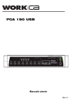
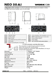
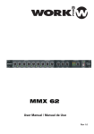
PCA 410
User Manual
Rev 1.1
EN
SAFETY RELATED SYMBOLS
WARNING:
TO REDUCE THE RISK OF FIRE OR
ELECTRIC SHOCK, DO NOT EXPOSE
TO RAIN OR HUMIDITY. DO NOT
REMOVE COVER. THIS PRODUCT IS
NOT INTENDED FOR USE OTHER THAN
STATED.
GRAPHICAL SYMBOLS EXPLANATION
This symbol, wherever used,alerts you to
the presence of un-isulated and dangerous
voltages within the product enclosure.
These are voltages that may be sufficient to
constitute the risk of electric shock.
External Connection
Always use proper ready-made insulated mains
cabling (power cord). Failure to do so could result
in shock or fire. If in doubt, seek advice from a
registered electrician.
Do not Remove Any Cover
This symbol, wherever used, alerts you to
important operating and maintenance
instructions. Please read.
Within the product are areas where high voltages
may be present. To reduce the risk of electric shock
do not remove any covers unless the AC mains
power cord is removed.
Protective Ground Terminal
AC mains (Alternating Current)
Covers should be removed by qualified service
personnel only.
No user serviciable parts inside.
Hazardous Live Terminal
ON: Denotes the product is turned on.
Fuse
OFF: Denotes the product is turned off.
WARNING
Describes precautions that should be observed to
prevent the possibility of death or injury to the user.
CAUTION
To prevent fire an damage to the product, use only
the recommended fuse type as indicated in this
manual. Do not short-circuit the fuse holder.
Before replacing fuse, make sure that the product
is OFF and disconnected from the AC outlet.
Protective Ground
Describes precautions that should be observed to
prevent damage to the product.
Before turning the product ON, make sure that it is
connected to Ground. This is to prevent the risk of
electric shock.
WARNING
Power Supply
Never cut internal or external Ground wires. Likewise,
never remove Ground wiring from the Protective
Ground Terminal.
Ensure that the mains source voltage (AC outlet)
matches the voltage rating of the product. Failure
to do so could result in damage to the product and
possibly the user.
Operating Conditions
Unplug the product before electrical storms occur
and when unused for long periods of time to reduce
the risk of electric shock or fire.
PAGE 1
Always install in accordance with the manufacturer´s
instructions.
To avoid the risk of electrtic shock and damage, do
not subject the product to any liquid/rain or moisture.
Do not use this product when in close proximity to
water.
Do not install this product near any direct heat source.
Do not block areas of ventilation.
User Manual
PCA 410
EN
FRONT PANEL
8
4 56 7
1 23
9
10
11
12
7. Ready LED
8. Power ON LED
1. Master Output Volume Control
2. Treble Tone Control
3. Bass Tone Control
9. Input Volume Controls (1-4, AUX 1-2, CHIME, SIREN)
10. CHIME (Switch ON/OFF)
11. SIREN (Switch ON/OFF)
12. Power Switch ON/OFF
4. Protection LED
5. Clip LED
6. Signal LED
* NOTE: Items 1 to 7 are shown for OUTPUT channel 1. Outputs 2 - 4 are identical.
13 14
15 16 17 18
31
(bottom side)
19
30 29 28
21
20
27
22
23
26 25 24
13. OUTPUT 3 (high/low impedance speaker outputs) 22. OUTPUT 2 (high/low impedance speaker outputs)
14. OUTPUT 4 (high/low impedance speaker outputs) 23. OUTPUT 1 (high/low impedance speaker outputs)
15. Mains input socket
24. Input 4 (COMBI(XLR3P-Jack)/balanced)
25. Input 4 (Terminal block)
16. AC fuse holder
17. Power amp Input (RCA phono)
26. Input 4 (Dip-switch for functions)
18. Pre output (RCA phono)
27. TEL/EMER input level control
19. AUX 2 input (RCA phono)
28. TEL/EMER input terminals
20. AUX 1 input (RCA phono)
29. SIREN terminals
21. Input 1 Priority Terminals
30. CHIME priority terminals
31. Input Voltage Selector
* NOTE: Items 24 to 26 are shown for INPUT 4. INPUTS 1 - 3 are identical.
PAGE 2
User Manual
PCA 410
EN
CONNECTIONS
Mains Connection (15)
The supply transformer has been designed for use on either 115V AC or 230 V AC, selected by a slide
switch on the bottom of the device. The amplifier is factory set at 230 V AC mains voltage.
Input Connection
Inputs 1-4 feature both balanced standard COMBI socket (1/4” stereo jack, and XLR 3P) and terminal blocks
on the rear panel.
Wiring is as follows:
(Front view)
PUSH
1
2
3
SLEEVE RING TIP
XLR 3P
1/4” STEREO JACK
Pin1 : Screen
Pin2 : Signal (live)
Pin3 : Signal (return)
Tip : Signal (live)
Ring : Signal (Return)
Sleeve : Screen
+
- GND
TERMINAL BLOCK
Pin+ : Signal (live)
Pin- : Signal (return)
GND : Screen
Turn the front panel potentiometers (9) clockwise to increase the volume or anticlockwise to reduce the volume.
Selected Functions by Dip-Switch block
NOTE: To ensure a correct
understanding. the
white coloured square
is considered the switch
in all pictures in this
user manual
Each input incorporates several functions
configurable through a dip-switch block:
ON
1
OFF
Switch 1: AUDIO SOURCE SELECTION: Setting the switch to the ON position, the input will accept
microphone level audio. Setting it to the OFF position, the input will accept LINE level.
Switch 2: PHASE INVERSION: Setting the switch to the ON position, the signal will be inverted 180º.
Setting it to the OFF position, the signal will be unaffected.
Switch 3: HIGH PASS FILTER: Setting the switch to the ON position, the input will be processed by a
high pass filter with a 200Hz cutoff frequency. Setting it to the OFF position, the
signal will be unaffected.
Switch 4: PHANTOM POWER: Setting the switch to the ON position, + 48V phantom power will be applied
for condenser microphones. Setting it to the OFF position, this function will be disabled.
The PCA 410 provides two auxiliary inputs (AUX 1-2) which may be used for connecting other signal sources
such as a Radio Tuner, MP3 player, computer, CD or Cassette player (LINE level). Connect the audio source to
the rear connectors (19, 20).Turn their respective potentiometers clockwise to increase the volume or
anticlockwise to reduce the volume.
These input sockets are standard RCA phonos, two sockets are supplied and these are linked together
internally in parallel, this allows stereo signal source to be used without the need to obtain a special lead,
however you may wish to check with the manufacturer of the signal source to ensure that no damage will result if
the left and right output channels are connected together in parallel.
Sleeve - Screen
Pin - Signal
RCA Phono plug connections
SLEEVE
PAGE 3
PIN
User Manual
PCA 410
EN
PRIORITY
INPUT 1 has the highest priority (apart fromTEL/EMER), overriding the rest of inputs. To activate the priority state
short-circuit the Priority terminals (21) on the rear panel.
CHIME ON/OFF
To activate the CHIME, both the front panel switch (10) must be depressed, and a short-circuit made between the
CHIME PRIORITY terminals on the rear panel(30). This will activate the chime function (‘Ding Dong’
pre-annoucement chime). Whilst the CHIME state is enabled all inputs will be overridden.
The volume of the CHIME can be set from the CHIME potentiometer on the front panel.
on
off
SIREN ON/OFF
SIREN can be activated in one of two ways:
- Pressing the front panel switch (11)
In that case, the SIREN WILL BE ACTIVATED UNTIL THE SWITCH IS PRESSED AGAIN (OUT POSITION).
- Making a short-circuit in the SIREN terminals (29) in the rear panel.
In that case, the SIREN WILL BE ACTIVATED UNTIL THE SHORT-CIRCUIT IS REMOVED.
Whilst the SIREN state is enabled all inputs will be overridden.
The volume of the SIREN can be set from the SIREN potentiometer on the front panel.
on
off
Telephone/Emergency (28)
The Telephone/Emergency input is for emergency announcements/signals and is not affected by the Master
volume control. The volume can be set by the tel. paging volume control (27).
The terminals allows connection of a telephone/paging system interface.
NOTE: The Telephone/Emergency input has the highest priority, all other units will be overriden.
+
GND
-
PAGE 4
User Manual
PCA 410
EN
Power In & Pre Out (17-18)
These sockets connect the mixer/preamplifier stage to the power amplifier stage. The connecting link must be
plugged in for normal operation as a mixer/amplifier. If a compressor/limiter, equalizer, or other external signal
processor is used in the sound system, connect the “PRE OUT” to the input of the external processor
and the output of the processor to “POWER IN” In the signal chain, “PRE OUT” is after the tone controls
and the master volume control.
Loudspeaker Connections
The PCA 410 includes 4 discrete outputs and each output section provides two different types of loudspeaker
outputs in each one: High impedance lines (25/70/100V) and low impedance (4, 8Ω). You can only use one of
these outputs at any one time; any attempt to use two or more of these may result in damage to the amplifier.
+
0
100V
0
100V
0
100V
4 ohm
Connecting a single speaker to the 4 ohm output
Connecting multiple speakers in parallel to the 100V output
+
-
0
70V
0
70V
0
+
-
70V
4 ohm
4 ohm
Connecting two speakers in series to the 8 ohm output.
Connecting multiple speakers in parallel to the 70V output
PAGE 5
User Manual
PCA 410
EN
DIMENSIONS
88 mm
410 mm
483 mm
TECHNICAL SPECIFICATIONS
Output Power (RMS)
Audio Inputs
4 x 250 W
4 MIC / LINE, 2 AUX level
INPUTS
MIC (Impedance/Sensitivity)
600 Ω / 2.8mV
LINE (Impedance/Sensitivity)
3k Ω / 316 mV
AUX (Impedance/Sensitivity)
50k Ω / 316 mV
OUTPUTS
Low Impedance
High Impedance Line
Frequency Response
EQ Control (Bass)
EQ Control (Treble)
S/N ratio
Total harmonic distortion
4/8Ω
25 / 70 / 100 V
50 Hz ‐ 17 kHz +/‐ 3dB
+/- 10 dB / 22 Hz ‐ 180 Hz /Centre Frequency 50 Hz
+/- 10 dB / 3k Hz ‐ 20 kHz /Centre Frequency 12 kHz
> 90 dB (Line), > 80 dB (MIC)
Less than 1% at 1 kHz, rated power
Chime
Two tone chime (‘Ding‐dong’ pre-announcement chime)
Priority
Tel./Emer. ‐ MIC 1
Main Supply AC power
Consumption
Dimensions
Weight
115 /230 V - 50/60 Hz
1800 W
483 x 132 x 410 mm ( W x H x D)
25.2 kg.
PAGE 6
User Manual
PCA 410
Important Warranty Information
WORK pro CA products are exclusively distributed in Europe by
Yamaha Music Europe GmBH.
Siemensstrasse 22-34
D-25462 Rellingen, b. Hamburg, Germany
EN
For information regarding the warranty and for user manuals in other languages
please go to:
FR
Les manuels d´utilisation en français ainsi que les informations concernant la
garantie son accessible à l´adresse suivante:
DE
Die deutschen Bedienungsanleitungen und Informationen zu der Gewährleistung
finden sie auf der Website:
ES
Para la información relativa a las condiciones de garantía y los manuales de usuario
en español, por favor acceda a la página web:
IT
Per le informazioni riguardanti la garanzia e per i Manuali d'Uso nelle altre lingue si
prega di visitare il sito:
http://www.workproca.com
This symbol on the product or on its packaging indicates that this product
shall not be treated as household waste. Instead it shall be handed over to
the applicable collection point for the recycling of electrical an electronic
equipment. By ensuring this product is disposed of correctly, you will help
prevent potential negative consequences for the environment and human
health, which could otherwise be caused by inappropriate waste handling
of this product. The recycling of materials will help to conserve natural
resources. For more detailed information about recycling of this product,
please contact your local city office, your household waste disposal service
or the shop where you purchased the product.
Manufactured by
EQUIPSON, S.A.