1
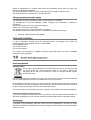
User’s Guide
Sistema de Calidad certificado
Nº Cert: 44 100 11 0904
Sistema Medioambiental certificado
Nº Cert: 44 104 11 0904
ZUMMO-INNOVACIONES MECÁNICAS, S.A.
011211/01
C/ CÁDIZ 4
46113 MONCADA (Valencia) España
Tel.: + 34 961301246
Fax: + 34 961301250
E-mail: [email protected]
ZUMMO-INNOVACIONES MECÁNICAS, S.A., in an ongoing effort to enhance its products,
reserves the right to modify machines without prior notice; for this reason, this user’s manual
may not contain the latest changes made.
INDEX
1
2
3
4
5
6
7
8
9
10
11
12
13
14
15
16
17
18
1
............................................................................................................................................. Pg.
TECHNICAL DATA ................................................................................................................ 1
IMPORTANT SAFETY INSTRUCTIONS ........................................................................... 1-2
INSTALLATION ..................................................................................................................... 2
START-UP ............................................................................................................................. 2
STOP ..................................................................................................................................... 2
COUNTER FUNCTION ......................................................................................................... 3
SAFETY SYSTEMS ............................................................................................................... 3
CLEANING ......................................................................................................................... 3-4
ACCESSORIES ..................................................................................................................... 4
MAINTENANCE ..................................................................................................................... 4
USE RECOMMENDATIONS ................................................................................................. 5
TROUBLESHOOTING ....................................................................................................... 5-6
ELECTRICAL DIAGRAM ...................................................................................................... 6
LIST OF COMPONENTS ................................................................................................... 6-7
GUARANTEE ..................................................................................................................... 7-8
WASTE AND RECYCLABILITY ............................................................................................ 8
PHOTOS ........................................................................................................................... 9-10
EXPLODED VIEW DRAWINGS ..................................................................................... 11-18
TECHNICAL DATA
POWER CONSUMPTION (W)
ORANGES PER MINUTE
FEED CAPACITY (Kg.)
HEIGHT
(mm)
SIZES
WIDTH
(mm)
WITH
RECEPTACLES
DEPTH
(mm)
LARGE CUPS
(Ø 90)
FRUIT SIZE
REGULAR CUPS
(Ø 75)
Ø (mm)
*SMALL CUPS
(Ø 60)
WEIGHT (Kg.) (without packaging)
275
10
1.5 -- **5.5
720
504
420
70-90
55-75
45-60
48
* Accessory not included with standard model.
** Capacity of display basket.
2
•
•
•
•
•
•
IMPORTANT SAFETY INSTRUCTIONS
Dear Customer: Before using your juice extraction machine, please carefully read this
user’s manual.
The machine exerts a great deal of pressure when squeezing fruit; for this reason, never
place hands or foreign objects in the squeezing area. (Fig. 1)
Always make sure fastening nuts on cups or the squeezing tray are tightened; otherwise,
serious damage to the machine may result. (Fig. 2)
Use special care when handling the blade to avoid the risk of injury. (Fig. 3)
To prevent risks, all repairs should be performed by technical personnel.
The company assumes no liability whatsoever if damage is due to improper machine use or
the failure to follow the instructions contained in this manual.
1
•
3
•
•
•
•
•
•
•
•
4
•
•
•
•
•
5
Request technical service from the company that supplied that machine to you; in the event
that it cannot be located, contact the factory (data on the cover of this manual).
INSTALLATION
Attention! The machine weighs 48Kg. When moving machine, we suggest that this be
accomplished by two persons. The best way to handle a machine is to use one hand to get
a grip underneath the rear and the other placed beneath the squeezing tray. (Fig. 4)
Place the machine on a sufficiently sturdy and stable base.
Ensure that the machine’s voltage and frequency match the values of your electrical
installation. See the identification plate. (Fig. 5)
Use an electrical outlet that is equipped with an effective earth connection. This outlet
should be used exclusively by the juice extraction machine. Do not plug other appliances
into the outlet.
Before turning on the machine, it is recommended that the pieces that will be in contact with
juice be cleaned first (cups, balls, blade, tray, filter and plastic front).
Turn on the power switch. (Fig. 6) If no message appears on the display (Fig. 7), this
means that there is a lack of voltage; in this case, make sure that you have plugged the
machine into a live line and that the power switch is turned on. Once this problem has been
taken care of, one of the following three messages will appear: StoP, a number , C
If the StoP message appears on the display, the machine cannot be started up because the
safety system prevents it. In this case, check the following:
a The cover is properly in place, with its clasps properly fitted inside the slots. (Fig. 8
& 9)
b The tray that holds the squeezer and the blade are properly in place, with the
fastening screws tightened. (Fig. 10)
If a number or the letter C appears on the display, the machine is ready for normal
operation.
START-UP
Once the machine is turned on, the display will show a number between 1 and 50 or the
letter C. The number indicates the quantity of oranges to be squeezed and the letter C
means that oranges will be squeezed without interruption for approximately 30 minutes.
Depending on the number of oranges that you want to squeeze, keep pressing the SELECT
button and the number on the display will increase from 1 to 50, and then the letter C will
appear (1,2,3,..........48,49,50,C,1,2,3.....). If you keep the SELECT button depressed for
more than 3 seconds, the number will decrease.
Perform this operation until the desired quantity appears.
Once a quantity is selected and an operation is performed, the machine will store this
information (even if it is shut off) until a new selection is made.
When the ON button on the panel is pressed, the machine will squeeze the number of
oranges shown on the display. During the process, the number of oranges left to squeeze
will appear on the display. If you want to repeat the operation, simply press the ON button.
To stop the process, press the STOP button.
STOP
With the machine running, press the StoP button. On the display a 0 will appear and the
machine will stop when the cups reach the vertical position. Afterwards, the display will show
the number of the previous selection.
2
6
COUNTER FUNCTION
If you want to know the total number of operations* performed, press the STOP button while
the machine is not running and this number will appear on the display for a few seconds.
Keep in mind that all machines leave the factory with 400 – 500 operations.
The display is limited to five digits, making it so a maximum of 99,999 operations can be
displayed. But if you want to know the number of times that the counter has turned over, turn
off the machine using the power switch and turn it back on again while holding down the
STOP button. The number that appears is the number of times the counter has turned over.
*(operation = complete set of steps in squeezing a piece of fruit.)
7
SAFETY SYSTEMS
The machine is equipped with several safety systems:
1 If the cover is not properly in place, with its clasps fully fitted inside the slots (Figs. 8
& 9), the display will show the StoP message and the buttons will not respond.
2 If the tray holding the squeezer and the blade are not properly in place, and the
nuts not tightened, the machine will not run and StoP will appear on the display
(Fig. 10)
3 If for some reason the machine were to become blocked while running, the motor
will automatically be stopped after a few seconds, and a blinking A will appear on
the display, waiting for the cause of the blockage to be removed.
4 The machine is equipped with a system of thermal protection in the motor. In the
event of overheating, the machine will stop and the display will show the StoP
message. In such a case, wait roughly five minutes for the temperature to go down,
at which point StoP will be replaced on the display by the last selection. Check to
make sure the ventilation grating is unobstructed.
5 If no message appears on the display, this will be due to the lack of voltage. Check
that the power switch is turned on and that the safety fuse to the power jack has not
burnt out. Observe that there are two fuses (Fig.11): the first fuse is the one that
may be burnt out while the second one is the spare fuse.
8
CLEANING
We recommend that the squeezing area be cleaned on a daily basis.
It is recommended to halt the machine by pressing StoP before cleaning (never stop using the
main breaker switch), as in this way all the parts to be cleaned will be easily extractable and
replaced. Failure to follow this recommendation will cause the machine to stop in a position that
impedes cleaning and possibly lead to breakage of parts due to poor handling.
• With the stopped machine following the previous process, DISCONNECT the MACHINE of
the POWER SWITCH (Fig. 6). The digital selector display will shut off.
• Remove the cover and wipe it with a damp cloth (ATENTION!: NEVER clean it with
products that can scratch it).
• The tray and blade are removed by unscrewing the nuts on the tray shafts and pulling
outwards horizontally (never extract the set throwing of the blade). Also unscrew the balls
or bevel-headed squeezers that are inside the tray that holds the squeezers (Fig. 15 &
16); underneath each one of them there should be one washer (Fig. 22), be careful not to
lose them! These pieces can be put in the washing machine or cleaned manually. TAKE
EXTRA CARE WITH THE BLADE (Fig. 3) since it is very sharp and may cause injury.
• To remove the cups we recommend that you loosen the fastening screws a little and pull
outwards; they will be released and can then be easily removed.
3
•
WARNING! Do not was the GREY DRIP TRAY (Ref. 0508008G) using hot water or
dishwasher at temperature over 40ºC. In case of distortion of the Drip Tray, this will not be
covered by the guarantee.
Assembly
After everything is washed, put it back in place in the following order:
1 Screw on the balls is the tray that holds the squeezers. Make sure that washers are put
in place beforehand and that the balls are properly tightened.
2 Check that the rubber bands of the blade are properly in place (Figs. 19 & 20). Insert the
blade inside the tray.
Assemble this set on the machine’s three shafts
simultaneously. (Fig. 12). Never mount the blade on the tray afterwards!! When it
makes contact with the bottom, fit the projecting part of the blade into the front guide
(Fig. 13).
3 Place the cups on the shafts and tighten the fastening nuts.
4 The cover is put back in place by fitting its clasps into the slots located on both front
sides (make sure that the clasps fit correctly into the slots). (Fig. 8 y 9)
Before starting up the machine, make sure that:
• The tray and blade have been properly fitted into place and screwed down.
• The blade has been properly fitted into place and in the horizontal position.
• The nuts on the cups are properly tightened.
• The correct sets of balls and cups have been used (see the section entitled
“accessories”).
In the event that the tray, balls or cups were not properly fitted into place, damage may be done
to these pieces and the inside of the machine. (Problems not covered by the guarantee since
they are errors made by the operator).
Cleaning the loader
Lift the loader up and it will come off easily, with the top of the machine remaining totally
uncovered. After cleaning it, put it back in place by fitting the legs into their respective
openings. (Fig. 14)
9
ACCESSORIES
Depending on the size of the fruit that you want to squeeze, the machine has several different
sets of cups and balls to choose from:
a Dark-coloured Cups and Balls for fruits with diameters between 55 and 75 mm.
(Fig. 15).
b Bright-coloured Cups and Balls for fruits with diameters between 70 and 90
mm. (Fig. 16).
c (Optional). Small red cups and balls for fruit with a diameter between 45 –
60mm. (Fig. 17).
Regardless of the set used, the blade and the squeezing tray will always remain the same.
ATTENTION!: Do not mix elements of different sets together.
10
MAINTENANCE
The only maintenance that the machine requires is to periodically lubricate the paddle shaft.
(Fig. 18). Always use grease approved for use with food products.
4
11
•
•
USE RECOMMENDATIONS
Make sure you are using the right squeezing parts (Balls & Cups) for the size of fruit you
wish to squeeze. If the fruit to squeeze is too big or too small for the squeezing kit used, the
quality of the juice may decrease, getting a bitter juice flavour.
We recommend to switch off the machine when is not going to be use. (Fig. 6)
12
TROUBLESHOOTING
Problem
The display does
not become lit
Cause and/or solution
Lack of electrical current.
Fuse burnt out. (Fig. 11-1)
Power cable improperly connected.
Turn on the power switch. Fig. 6
Humidity in electronic plate. Provide dry heat to the plate.
Cover not properly in place. (Figs. 8 & 9)
StoP appears on
Tray that holds squeezers out of place. (Fig.10)
the display
Check to see if frozen oranges are being squeezed.
The letter A
appears blinking on Check if peelings have piled up on the tray that holds squeezers.
Check to see if balls have been left un-tightened.
the display
Check to see if peelings are left stuck to the inside of cups.
To unblock the machine, use an Allen key of 5mm which you will find at
the right side of the grid. Introduce it in the right side lateral hole
(Fig.21) and, with the machine switched off, turn the key clockwise till
cups are up and the machine is unblocked.
LOOK OUT: before switching the machine, make sure that the key is
out of the anchorage.
Nuts on the cups are improperly tightened.
The cups break
Excess of washers under the balls.
The balls on the tray that holds squeezers are loose.
The blade is not properly positioned.
Do not place Dark-coloured cups with large Bright-coloured balls (Ø80).
Oranges are either too small or too large for the cups.
The blade has been placed over its shaft.
Blade breakage
The Balls are loose.
The balls break
The nuts on the cups are improperly tightened.
More than two washers have been placed under each ball.
Washers are missing under balls.
Oranges are not
Orange peels are too thin; place a maximum of one washer under balls.
thoroughly
squeezed
The paddle shaft is too dry; proceed to grease it. (Fig. 18)
Oranges dash out
from the paddle
The process that must follow to modify the STOP point
The machine does
not stop with cups from the electronic plate is the following one:
in vertical position. - To disconnect the machine by means of the back switch.
- To connect again simultaneously that STOP is pressed. four numbers
will appear in the screen.
With the four numbers in screen ( it appears 3 seconds) press
button ON. A number from the 0 to the 9 will appear on the left of the
screen. The shown number corresponds to tenth of second of delay in
not operating of the machine, for which and if you need to stop the
machine you have to select an inferior number than the shown one in
screen. In order to change this number, press ON (when the screen
shows the number to the left) number will change.
5
Enabling electronic to memorize this number, you will have to wait 5
seconds (the screen will show then a number in the central position,
corresponding to the number of oranges selected).
Verify that the unemployment point is the correct one. If it’s not, repeat
the process with another value.
For any queries or request for spare parts, please state the model and identification
number of your machine (Fig. 5).
13
1
2
3
4
5
14
LEGEND FOR ELECTRICAL DIAGRAM
Fuse
Power switch
Electronic plate
Counter micro-switch
Cover micro-switch
6
7
8
9
Cover micro-switch
Motor
Condenser
Tray micro-switch
LIST OF COMPONENTS
Code
Description
Code
Description
0501A00B
CHASSIS
0502007A
COVER CLASP (COMPACT FRONT COVER)
0502001G
GREY SQUEEZER TOP
0502008
SIDE BASE STOP
0502002C
STAINLESS STEEL FRONT
0502009
SILICONE WASHER
0502003D
BODY
0502011A
LOWER GRILL ZUMMitO
0502004
BLADE SLIDE COVER
0502A00B
COMPACT FRONT COVER
0502005
CUP SLIDE COVER
0503001
FEEDER PADDLE
0502006B
COMPACT FRONT COVER (PLASTIC ONLY)
0503003
FEEDER LEVER SHAFT
6
Code
Description
Code
Description
0503004A
FEEDER LEVER
0506001/2A
PROGRAMMER ZUMMEN 230V
0503005A
FEED PADDLE ROD
0506002C
MICRO-COUNTER HOLDER
0503006
FEEDER SPRING SUPPORT
0506003
COVER MICRO HOLDER
0503007
FEEDER SPRING
0506005/1
COVER MICRO HOOP
0503010
BASKET AND FEEDER RAMP
0506006/1
SQUEEZING TRAY-MICRO CLAMP
0504001A
GEAR BOX TYPE SX-50 i=36:1 (BOX)
0506007
MICRO (SHORT)
0504002B
MOTOR 0,33CV, 225v 50Hz
0506008
MICRO (LONG)
0504005
GEAR BOX POLEY (60XL 037)
0506010
POWER CORD
0504006
PINION
0506014
POWER BASE WITH FUSES
0504007
BOLT & PINIONS WASHER
0506015
BLACK BIPOLAR SWITCH
0504008
RACK
0506021
CONNECTION
0504009A
BOLT (UPPER CONNECTING ROD)
0508002
Z06 S.STEEL BIN
0504010
CONNECTING ROD
0508008G
GREY DRIP TRAY
0504012
RACK SLIDE
0508009
DRIP GRATE
0504013
PRESS PLATE FASTENER
0508013
RUBBER MOUNT (85mm)
0504014-1
CUP SLIDE
4/9
MOTOR POLEY (14 XL 037)
0504015A
BLADE SLIDE
6/2
BOLT (BALL BEARING HOLDER)
0504016
CUP SLIDE BAR
10/1/2A
Z06 GREY SERIGRAPHY
0504017
CUP SLIDE SPRING Z05-Z08
10/21
CONDENSER 30 µf
0504019
BELT 190XL 037
I-7982- Ø3.5X9.5
COUNTERSUNK HEAD SCREW Ø3.5X9.5 DIN7982
I-7985-M4X12
DIN-7985 STAINLESS STEEL BOLT M4X12
I-84-M4X10
S.STEEL SCREW M4X10 DIN-84
I-9021-M4
FLAT WASHER M4 DIN-9021
I-963-M4X10
COUNTERSUNK HEAD SCREW M4X10 DIN963
I-985-M4
S.STEEL SCREW M4 DIN-985
0504020
PLASTIC WASHER 7,5/15 X 1,5
0504026
SHAFT (GEAR BOX SX-50)
0504027
MOTOR ANCHOR
0504027-2
MOTOR CORRECTION ATTACHEMENT
0504028
BEVEL GEAR+LOWER CONNECTING ROD
BOLT
0504A00
PRESS SET
0504B00
BLADE SHAFT
ROD.608ZZ
BALLS BEARING 608ZZ-C3 SKF
T-30/15-M6
MOTOR PAD T-30/15-M6
T-471-E8
SAFETY RING E-8 DIN-471
T-6885A-6X6X28
COTTER 6x6x28 DIN-6885A
0504B04
BLADE SHAFT COTTER
0505002G
SQUEEZING TRAY (GREY)
0505003G
BLADE Z05 (GREY)
0505004G
BALL 80 (BRIGHT GREY)
T-7991-M6X30
COUNTERSUNK HEAD SCREW M6X30 DIN7991
0505005G
BALL 67 (DARK GREY)
T-912-M8X35
ALLEN SCREW M8x35 DIN-912
0505006G
CUP 90 (BRIGHT GREY)
T-912-M8X80
ALLEN SCREW M8x80 DIN-912
0505007G
CUP 75 (DARK GREY)
T-933-M8X20
SCREW EXAG. M8x20 DIN-933
0505009A
CUP SHAFT
V0001
INSULATING PAD (150X150)
0505010A
FASTENING NUT WITH RAKED JOINT
V0016
GROUND CONNECTOR
0505010A-1
CUP NUT
V0017
SAFETY NUT NUL-515-1B
0505010A-2
FASTENING NUT JOIN ∅20
V0018
CHAIN JOINT 06B-1 9,525x5,72
0505011A
SQUEEZING-TRAY SHAFT
V0081
FRONTCOVER CLASP KIT Z05 (2003)
0505014
TRAY FILTER
V0133
JUICE TRAY WASHER
0505016
PEEL EXTRACTING BANDS
0505020
M5 S.STEEL KNOB
15
GUARANTEE
ZUMMO-INNOVACIONES MECÁNICAS S.A., through its official distributor, guarantees their
machines for a period of TWO YEARS or for 200,000 squeezing cycles, valid from the date of
delivery to the distributor, in accordance with the following conditions:
This guarantee covers all material or manufacturing defects.
If any faults are found during normal use and within the guarantee period, the defective parts
will be replaced free of charge.
7
Repair or replacement of machine parts during the guarantee period, does not imply and
extension in guarantee expiration.
The guarantee shall be valid only when presented with the original purchase invoice.
The original parts are covered by a six-month guarantee.
This guarantee does not cover
Any damages not directly caused by a fault of manufacturing or materials.
Any damages due to incorrect installation, abuse, improper use, modifications, accidents or
negligence.
Any parts scratched due to use of improper washing.
Labour not covered by this guarantee.
Any damages caused by unauthorised staff or materials.
Any defects caused by use wearing down; in individual the following component:
•
0505016 PEEL EXTRACTING BANDS
.
Technical assistance
In case of damages caused during the guarantee period, we suggest you contact the
Authorised Dealer who supplied the unit, or call ZUMMO:
E-mail:[email protected]
Tel:+34.96.1301246
Fax:+34.96.1301250
Any repairs not authorized by ZUMMO during the guarantee period will cause immediate
termination of the guarantee.
16
WASTE AND RECYCLABILITY
Used equipment
European Union
This symbol indicates that the electrical and electronic parts in the machine must
not be discarded with general domestic waste. If you wish to discard this
equipment, do not use your everyday bin! There is a special collection system
for these products.
For more information on the collection and recycling of this product, contact your local collection
service, waste disposal controller or the dealer who sold you the product.
By discarding the product correctly, you will be helping to preserve natural resources (recycling
of materials) and to prevent possible harmful effects on the environment and on the health of
people, through the improper treatment of the discarded product.
The incorrect removal of this waste may carry a penalty, in accordance with national legislation.
Countries outside the European Union
If you wish to dispose of this product, do so in conformity with the current national legislation or
with other regulations from your country relevant to electrical and electronic equipment waste.
Packaging
To dispose of the packaging, take into account the local regulations for this type of waste.
Separate the different waste materials from the packaging and send them to your nearest waste
collection centre.
8
9
10