1
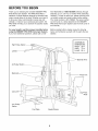
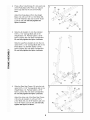
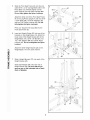
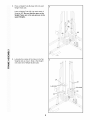
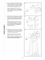
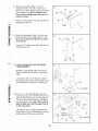
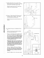
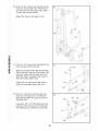
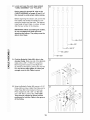
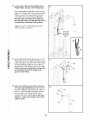
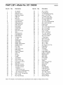
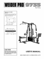
Patent Pending
Model No. 831.159390
Serial No.
The serial number can be found in the
location shown below. Write the serial
number in the space above.
Serial Number Decal
EXERCISE
EQ
u
I
PM
ENT
HELPLINE!
1-800-736-6879
CAUTION
Read all precautions and instructions in this manual before using
this equipment. Save this manual
for future reference.
USER'S MANUAL
SEARS, ROEBUCK AND CO., HOFFMAN ESTATES, IL 60179
TABLE OF CONTENTS
FULL 90 DAY WARRANTY ...............................................................
IMPORTANT PRECAUTIONS .............................................................
BEFORE YOU BEGIN ...................................................................
ASSEMBLY ...........................................................................
HOW TO USE THE HOME GYM SYSTEM ..................................................
WEIGHT RESISTANCE CHART ..........................................................
TROUBLE-SHOOTING AND MAINTENANCE ................................................
CABLE DIAGRAMS
...................................................................
ORDERING REPLACEMENT PARTS ...............................................
2
3
4
5
26
28
29
30
Back Cover
Note: A PART IDENTIFICATION CHART and a PART LIST/EXPLODED DRAWING are attached to the center of
this manual. Remove the PART IDENTIFICATION CHART and the PART LIST/EXPLODED DRAWING before
beginning assembly.
FULL 90 DAY WARRANTY
For 90 days from the date of purchase, if failure occurs due to defect in material or workmanship in this
SEARS WEIGHT SYSTEM EXERCISER, contact the nearest SEARS Service Center throughout the
United States and SEARS will repair or replace the WEIGHT SYSTEM EXERCISER, free of charge.
This warranty does not apply when the WEIGHT SYSTEM EXERCISER is used commercially or for
rental purposes.
This warranty gives you specific legal rights, and you may also have other rights which vary from state
to state.
SEARS, ROEBUCK AND CO., DEPT. 817WA, HOFFMAN ESTATES, IL 60179
2
IMPORTANT PRECAUTIONS
WARNING: To reduce the risk of serious injury, read the following
using the home gym system.
1. It is the responsibility of the owner to ensure
that all users of the home gym system are
adequately informed of all precautions.
2.
3.
4.
12. Always stand on the foot plate when performing an exercise that could cause the
home gym system to tip.
Inspect and tighten all parts often. Replace
any worn parts immediately. All cables
should be replaced every two years.
6.
Always wear athletic shoes for foot protection.
7.
Keep hands and feet away from moving
parts.
.
11. The lock pin must always be inserted
through both the rear seat frame and leg
lever frame and clipped in place on the rear
seat frame.
Use the home gym system only on a level
surface. Place a mat beneath the home gym
system to protect the floor or carpet.
Keep children under 12 and pets away from
the home gym system at all times,
8.
10. When using the leg lever station, always be
sure that the lock pin is fully inserted and
that the lock pin is clipped in place on the
rear seat frame (see page 27).
Read all instructions in this manual and in
the accompanying literature before using the
home gym system.
5.
important precautions before
13. Make sure that the cables remain on the pulleys at all times. If the cables bind while you
are exercising, stop immediately and make
sure that the cables are on all of the pulleys.
14. Always disconnect the lat bar from the home
qym system when performinq an exercise
that does not use the lat bar.
15. If you feel pain or dizziness at any time while
exercising, stop immediately and begin cooling down.
Never release the press arm, butterfly arms,
leg lever, leg press plate, lat bar, row bar, ab
strap, or nylon strap while weights are
raised. The weights will fall with great force.
16. The home gym system is intended for home
use only. Do not use the home gym system
in any commercial, rental or institutional setting.
When using the leg press station, always be
sure that the lock pin is fully inserted and
that the lock pin is clipped in place on the
adjustment tube (see page 27).
WARNING: Before beginning this or any exercise program, consult your physician. This is especially
important for persons over the age of 35 or persons with pre-existing health problems. Read all
instructions before using. SEARS assumes no responsibility for personal injury or property damage
sustained by or through the use of this product.
3
BEFORE YOU BEGIN
Thank you for selecting the versatile WELDER <R_
PRO
9735 Home Gym System. The PRO 9735 offers a
selection of weight stations designed to develop every
major muscle group of the body. Whether your goal is
to tone your body, build dramatic muscle size and
strength, or improve your cardiovascular system, the
PRO 9735 will help you to achieve the specific results
you want.
free HELPLINE at 1-800-736-6879, Monday through
Saturday, 7 a.m. until 7 p.m. Central Time (excluding
holidays). To help us assist you, please note the product model number and serial number before calling.
The model number is 831.159390. The serial number
can be found on a decal attached to the WELDER®
For your benefit, read this manual carefully before
using the WELDER ® PRO 9735 Home Gym System.
If you have additional questions, please call our toll-
Before reading further, please review the drawing
below and familiarize yourself with the parts that are
labeled.
PRO 9735 Home Gym System (see the front cover of
this manual).
ASSEMBLED
DIMENSIONS:
High Pulley Station --
Lat Bar
Height:
Width:
79 in.
70 in.
Length:
64 in.
Butterfly Arms
Ab Pulley Station
Backrests
Press Arm
Leg
Leg Press
Plate
Low Pulley
Station
Foot Plate
Weight Stacks
4
ASSEMBLY
Before beginning assembly, carefully read the
following information and instructions:
As you assemble this product, be sure that all
parts are oriented as shown in the drawings.
• Place all parts in a cleared area and remove the
packing materials; do not dispose of the packing
materials until assembly is completed.
Tighten all parts as you assemble them, unless
instructed to do otherwise.
Assembly is divided into four stages: 1) frame
assembly, 2) press and butterfly arm assembly,
3) cable and pulley assembly and 4) seat and
backrest assembly. The hardware for each stage
is packaged separately.
• Wait until you begin each assembly stage to open
the parts bag labeled for that assembly stage.
For help identifying the small parts used in
assembly, use the PART IDENTIFICATION
CHART located in the center of this manual.
Note: Some small parts may have been preattached for shipping. If a part is not in the parts
bag, check to see if it has been pre-attached.
THE FOLLOWING TOOLS (NOT INCLUDED) ARE
REQUIRED FOR ASSEMBLY:
• Two (2) adjustable wrenches
• One (1) standard
screwdriver
• One (1) phillips screwdriver
• One (1) rubber mallet
t_
• Lubricant, such as grease or petroleum jelly,
and soapy water will also be needed.
Assembly will be more convenient if you have the
following tools: A socket set, a set of open-end or
closed-end wrenches, or a set of ratchet wrenches.
Before beginning assembly, be sure that
you have read and understand the information in the box above.
Locate and open the parts bags labeled
"FRAME ASSEMBLYmMETAL"
and
"FRAME ASSEMBLYmPLASTIC."
i_il_
LI,I L
Insert four 5/16" x 2 1/2" Carriage Bolts (49)
up through the Press Base (13). Insert four
5/16" x 2 1/2" Carriage Bolts up through the
Weight Base (14). Insert a 3/8" x 4" Carriage
Bolt (57) up through the Weight Base.
Attach the Press Base (13) to the Weight
Base (14) with two 5/16" x 2 3/4" Bolts (55),
two 5/16" Washers (20) and two 5/16" Nylon
Locknuts (40). Fully tighten the Nylon
Locknuts.
i
58
Press three 2" Square Outer Caps (58) onto
the Weight Base (14) in the indicated locations.
iiI
55
58
13
14
49
57
58
49
4O
49
,
/
Press a Row Tube Endcap (51) into each side
of the Pulley Base (79). Press a 2" Square
Inner Cap (56) into the end of the Pulley
Base.
2
55
2O
14
51
.d
Attach the Pulley Base (79) to the Weight
Base (14) with two 5/16" x 2 3/4" Bolts (55),
two 5/16" Washers (20) and two 5/16" Nylon
Locknuts (40). Do not fully tighten the
Nylon Locknuts.
iiii
79
i iii _
ii _i__
,
Slide the Ab Upright (1) onto the indicated
5/16" x 2 1/2" Carriage Bolts (49) in the
Weight Base (14). Partially tighten a 5/16"
Nylon Locknut (40) onto each Carriage Bolt.
Do not fully tighten the Nylon Locknuts.
56
3
i_I_ _ii i
Slide the Leg Press Upright (4) onto the indicated 5/16" x 2 1/2" Carriage Bolts (49) in the
Press Base (13). Partially tighten a 5/16"
Nylon Locknut (40) onto each Carriage Bolt.
Do not fully tighten the Nylon Locknuts.
_! iii
ii_
ii
1,1,1
4
i/,i--
i ii_i
i/
4O
ii
13
49
,
Slide the Rear Seat Frame (16) onto the indicated 5/16" x 2 1/2" Carriage Bolts (49) in the
Weight Base (14). Partially tighten a 5/16"
Nylon Locknut (40) onto each Carriage Bolt.
Do not fully tighten the Nylon Locknuts.
4
2O
16
Attach the other end of the Rear Seat Frame
(16) to the Ab Upright (1) with two 5/16" x
2 3/4" Bolts (55), two 5/16" Washers (20) and
two 5/16" Nylon Locknuts (40). Do not fully
tighten the Nylon Locknuts.
iii_
i
6
,
/
Slide the Front Seat Frame (8) onto the indicated 5/16" x 2 1/2" Carriage Bolts (49) in the
Press Base (13). Partially tighten a 5/16"
Nylon Locknut (40) onto each Carriage Bolt.
Do not fully tighten the Nylon Locknuts.
5
4O
8
56
Attach the other end of the Front Seat Frame
(8) to the Leg Press Upright (4) with two 5/16"
x 2 3/4" Bolts (55), two 5/16" Washers (20)
and two 5/16" Nylon Locknuts (40). Do not
fully tighten the Nylon Locknuts.
iiii
13
Press a 2" Square Inner Cap (56) into the
Front Seat Frame (8).
ii _i__
,
_! iii
6
Insert two Weight Guides (23) into one of the
brackets on the Weight Base (14). Attach the
lower ends of the Weight Guides (23) to the
Weight Base with a 5/16" x 6" Bolt (67), two
1/2" x 3/4" Spacers (69) and a 5/16" Nylon
Locknut (40). Do not overtighten the Nylon
Locknut.
Attach the other Weight Guides (23) to the
Weight Base (14) in the same manner.
it1
14
,
7
Slide eight Weights (90) onto each set of
Weight Guides (23). Be sure that the pin
grooves are on the indicated side of each
stack of Weights.
i/.I--
i/
Slide a Weight Bumper (27) onto each of the
Weight Guides (23).
69
90
ii
Pin
Grooves
9O
Pin
Grooves
i_ iii iii
ii ii
23
i
ii
7
23
,
Press a Weight Tube Bumper (26) into each
Weight Tube (25).
8
Insert a Weight Tube (25) into each stack of
Weights (90). Be sure that the pins on the
Weight Tubes are in the pin grooves in the
upper Weights.
/
ii _i__
9.
i/,I.I ¸
i/
Lubricate the insides of the holes in the Top
Weights (24) as shown. Slide a Top Weight
onto each set of Weight Guides (23).
9
ii
i_ iii iii
ii ii
i
ii
8
10. Press a 2" Square Inner Cap (56) into each
end of the Top Frame (2). Press a 2" Square
Inner Cap (56) into each side of the Butterfly
Frame (3). Press two 1" Round Inner Caps
(70) into the top of the Butterfly Frame.
10
4O
2O
7O
/
iiii
Attach the Butterfly Frame (3) to the Top
Frame (2) with two 5/16" x 2 3/4" Bolts (55),
two 5/16" Washers (20) and two 5/16" Nylon
Locknuts (40).
55
56
56
ii _i__
i_I_ _ii i
_! iii
ii_
ii
11. Attach the Top Frame (2) to the Ab Upright (1)
with two 5/16" x 2 3/4" Bolts (55), two 5/16"
Washers (20) and two 5/16" Nylon Locknuts
(40). Do not tighten the Nylon Locknuts
yet.
Attach the Butterfly Frame (3) to the
Press Upright (4) with two 5/16" x 3"
(92), the Support Plate (98) and two
Nylon Locknuts (40). Do not tighten
Nylon Locknuts yet.
11
,92
3
2
98
Leg
Bolts
5/16"
the
it1
12. Attach the upper ends of one set of Weight
Guides (23) to the Top Frame (2) with a 5/16"
x 6" Bolt (67), two 1/2" x 3/4" Spacers (69)
and a 5/16" Nylon Locknut (40).
12
4O
69
i/.I--
i/
Attach the upper ends of the other set of
Weight Guides (23) in the same manner.
ii
Before continuing, firmly tighten all nylon
Iocknuts used in steps 2 through 12.
i_ iii iii
ii ii
i
ii
9
69
23
i_i ii
ii_ i_
_iiii
i
13. Attach the Leg Press Plate (11) to the
Adjustment Tube (10) with a 5/16" x 2 1/2"
Bolt (39), two 5/16" Washers (20) and a 5/16"
Nylon Locknut (40). Be sure that the Leg
Press Plate and Adjustment Tube are oriented as shown.
10
2O
39
Press a 1 3/4" Square Inner Cap (48) into the
Adjustment Tube (10).
Angle
11
iitn
14. Attach the Adjustment Tube (10)to the Leg
Press Arm (9) with the Small Lock Pin (73).
Be sure the Leg Press Plate (11) is oriented as shown.
14
10
73_
Press two 2" Square Inner Caps (56) into the
Leg Press Arm (9).
56
i
ii
15. Locate and open the parts bag labeled
"ARM ASSEMBLY."
Attach the Large Bumper (53) to the Front
Seat Frame (8) with the #10 x 1" Tap Screw
(100).
Lubricate the 3/8" x 3 1/4" Bolt (71). Attach
the Leg Press Arm (9) to the Press Base (13)
with the Bolt and a 3/8" Nylon Locknut (42).
r-..i 71--Lubricate
i/,I,I
100
16. Press a 1" x 7/8" Plastic Bushing (54) onto
each welded spacer on the Press Frame (12).
Slide the Press Frame onto the Press Base
(13) so that the Plastic Bushings are aligned
with the indicated tube. Note: This will be a
tight fit. Make sure that the higher hole is
on the side shown.
Tube
Lubricate the 3/8" x 8" Bolt (52). Attach the
Press Frame (12) to the Press Base (13) with
the Bolt and a 3/8" Nylon Locknut (42).
i
52--Lubricate
iiI
!.
54
10
17. Attach a Press Arm (7) to one side of the
Press Frame (12) with two 5/16" x 2 1/2" Bolts
(39) and two 5/16" Nylon Locknuts (40).
i i_i I
i
i
i_i iii
39
Attach the other Press Arm (7) to the Press
Frame (12) in the same manner.
/
i
i
iii iII_I
ii
i
i
i
18. Press a 1" Round Inner Cap (70) into one of
the Press Arms (7). Press a 1 3/4" Square
Inner Cap (48) into the Press Arm.
48
Repeat this step for the other Press Arm (not
shown).
O')
19. Lubricate both axles on the Butterfly Frame
(3).
19
Refer to the drawing and identify the Right
Arm (5) and the Left Arm (6).
i ii_i
/
3
Lubricate Axle
Press a 1 3/4" Square Inner Cap (48) into the
upper end of the Left Arm (6). Slide the Left
Arm onto the indicated axle. Note: Be careful
not to confuse the Left Arm with the Right
Arm (5). Be sure that the upper end of the
Left Arm is behind the indicated bracket
on the Butterfly Frame (3).
IMPORTANT NOTE: Before assembling the
1" Retainers (45) used in this step, be sure
that you thoroughly understand the step.
The Retainers can be assembled only once.
If they must be removed, you will need to
order new Retainers.
Tap two 1" Retainers (45) and a 1" Round
Outer Cap (46) onto the axle. Be sure that
the teeth on the Retainers bend toward the
ii
i I
Round Outer Cap, as shown in the inset
drawing.
Attach the Right Arm (5) in the same manner.
11
20. Press a 1 3/4" Square Inner Cap (48) into the
lower end of the Left Arm (6). Wet the lower
end of the Left Arm with soapy water. Slide a
10" Pad (22) onto the Left Arm.
2O
Repeat this step with the Right Arm (5).
5_
i
i
ii
ii_i
ii
i
i
22 ¸
i
21. Press a 1 3/4" Square Inner Cap (48) into the
top of the Leg Lever Frame (30).
21
Slide the Leg Lever Frame (30) into the Rear
Seat Frame (16). Align one of the holes in the
Leg Lever Frame with the upper hole in the
Rear Seat Frame. Insert the Large Lock Pin
(96) into the Rear Seat Frame.
iii_ ii
1
Tighten the 1/4" x 5/8" Screw (99) into the
lower hole in the Rear Seat Frame (16).
99 /
i i
ii
i I
i
22. Press a 1 3/4" Square Inner Cap (48) into
each end of the Leg Lever (15). Attach the
Small Bumper (95) to the Leg Lever with a 1"
Tap Screw (72).
22
43
Lubricate a 3/8" x 2 1/2" Bolt (65). Attach the
Leg Lever (15) to the Leg Lever Frame (30)
with the Bolt and a 3/8" Nylon Jam Nut (43).
15J
i I
iii_
i
12
'
3O
23. Locate and open the parts bags labeled
"CABLE ASSEMBLY" and "PULLEYS."
23
iil l i_i
During steps 23 through 58, refer to the
CABLE DIAGRAMS on pages 30 and 31 of
this manual to verify proper cable routing.
i
ii
Before beginning this section, fully unwind the
five Cables and identify the Cables by comparing the lengths and the ends. The approximate length of each Cable, in inches, is listed
after the key number in the drawing.
E-
IMPORTANT: While assembling the Cables,
do not overtighten the bolts and nuts
attaching the pulleys. The pulleys must be
able to turn freely.
i
'(_85--72.5"
-86-1°3''
i
iii
i
iiii
87--148.75"
89--209.5"
i/,IJ_
24. Find the Butterfly Cable (85)mthis is the
shortest Cable. Slide one end of the Butterfly
Cable onto a 3/8" x 1" Bolt (77). Insert the
Bolt through the bracket on the Right Arm
(5).Thread a 3/8" Nylon Locknut (42) onto the
Bolt, but do not fully tighten it. Leave just
enough room for the Cable to pivot.
24
85
iii_ ii
i_ iii iii
25. Wrap the Butterfly Cable (85) around a 3 1/2"
Pulley (82) as shown. Attach the Pulley and a
Cable Trap (80) to the bracket on the Leg
Press Upright (4) with a 3/8" x 2" Bolt (50)
and a 3/8" Nylon Locknut (42). The Cable
Trap must be oriented as shown and be
positioned to hold the Cable in the groove
of the Pulley.
ii_ ii
i
ii
13
25
42
26. Locate one of the pre-assembled pairs of
Pulley Plates (31) and 3 1/2" Pulleys (82).
26
iil l i_i
i
ii
Route the Butterfly Cable (85) under the indicated 3 1/2" Pulley (82). The end of the Pulley
Plates (31)with two holes should be downward. Refer to the inset drawing. Be sure
that the Cable is between the Cable Trap
(80) and the Pulley, and that the Cable Trap
is positioned to hold the Cable in place.
Tighten the 3/8" x 2" Bolt (50) and the 3/8"
Nylon Locknut (not shown).
End with
two holes
should be
down
89-
i
iii
i
I180
iiii
27. Wrap the Butterfly Cable (85) around a 3 1/2"
Pulley (82) as shown. Attach the Pulley and a
Cable Trap (80) to the other side of the bracket
on the Leg Press Upright (4) with a 3/8" x 2"
Bolt (50) and a 3/8" Nylon Locknut (42). The
Cable Trap must be oriented as shown and
be positioned to hold the Cable in the
groove of the Pulley.
i/
27
8O
ii
i_ iii iii
28. Note: The Left Arm (6) is shown removed
for easier part identification. Slide the other
end of the Butterfly Cable (85) onto a 3/8" x 1"
Bolt (77). Insert the Bolt through the bracket
on the Left Arm (6). Thread a 3/8" Nylon
Locknut (42) onto the Bolt, but do not fully
tighten it. Leave just enough room for the
Cable to pivot.
28
42
i
ii
14
29. Note: The 3 1/2" Pulley (82) in this step is
pre-assembled. It is shown removed for
easier part identification.
iil l i_i
i
ii
29
Locate the High Cable (86)mthis is the
shortest remaining Cable. Route the High
Cable around the 3 1/2" Pulley (82) attached
to the Top Frame (2). Be sure that the end of
the Cable with the ball is on the indicated
side of the Pulley and that the Cable is
between the Pulley and the post. Tighten
the 3/8" x 3 1/2" Bolt (66) and the 3/8" Nylon
Locknut (42), with the 3/8" Washer (38).
30. Wrap the High Cable (86) around a 3 1/2"
Pulley (82). Attach the Pulley and a Cable
Trap (80) to the Top Frame (2) with a 3/8" x
3 1/2" Bolt (66), a 3/8" Washer (38) and a 3/8"
Nylon Jam Nut (43). Be sure that the Cable
Trap is positioned to hold the Cable in
place.
i
2
38
42
86
3O
66
38
iii
i
iiii
ii/JJ 7
31. Locate the remaining pre-assembled
pair
of Pulley Plates (31) and 3 1/2" Pulleys
(82).
iii_ ii
31
Route the High Cable (86) under the indicated
3 1/2" Pulley (82). The end of the Pulley
Plates (31)with two holes should be downward. Refer to the inset drawing. Be sure
that the Cable is between the Cable Trap
(80) and the Pulley, and that the Cable Trap
is positioned to hold the Cable in place.
32. Wrap the High Cable (86) around a 3 1/2"
Pulley (82). Attach the Pulley to the Top
Frame (2) with a 3/8" x 2" Bolt (50) and a 3/8"
Nylon Locknut (42). The Cable must be
routed from the direction shown.
ii_ ii
i
31
8O
End with
holes should
be down
Tighten the 3/8" x 2" Bolt (50) and the 3/8"
Nylon Locknut (not shown).
i_ iii iii
86
ii
15
32
42
33. Attach the High Cable (86) to a Small "U"
Bracket (32) with a 1/4" Nylon Locknut (44)
and a 1/4" Washer (37). Do not completely
tighten the Nylon Locknut. It should be
threaded onto the end of the Cable so only
a couple of threads are showing above the
Nylon Locknut, as shown in the inset
drawing.
iil l i_i
i
i
ii
33
Attach the Small "U" Bracket (32) to the indicated Weight Tube (25) with a 5/16" x 1 3/4"
Bolt (68) and a 5/16" Nylon Locknut (40).
iii
i
iiii
i/,tJ_
34. Locate the Rear Cable (87)mthis is again
the shortest remaining Cable. Wrap the
Rear Cable around a 3 1/2" Pulley (82).
Attach the Pulley and two Pulley Covers (62)
to the Ab Upright (1) with a 3/8" x 4" Bolt (76),
two 3/8" Washers (38) and a 3/8" Nylon
Locknut (42). Do not overtighten the Nylon
Locknut; the Pulley should turn easily.
Make sure that the Cable is between the
i/
ii
i_ iii iii
Pulley and the post, and that the Pulley
Covers are turned so the wide tabs are on
the indicated side.
35. Wrap the Rear Cable (87) around a 3 1/2"
Pulley (82). Attach the Pulley and two Pulley
Covers (62)to the Ab Upright (1)with a 3/8" x
4" Bolt (76), two 3/8" Washers (38) and a 3/8"
Nylon Locknut (42). Do not overtighten the
Nylon Locknut; the Pulley should turn easily. Make sure that the Cable is between
the Pulley and the post.
34
62
Wide Tabs
must be
on this
side
35
ii ii
i
62
ii
16
iil l i_i
i
36. Route the Press Cable (88) over the indicated
3 1/2" Pulley (82) attached to the Pulley
Plates (31). The Cable must be routed from
the direction shown. Refer to the inset drawing. Be sure that the Cable is between the
Cable Trap (80) and the Pulley, and that the
Cable Trap is positioned to hold the Cable
in place.
36
iii
i
iiii
37. Wrap the Rear Cable (87) around a 3 1/2"
Pulley (82). Attach the Pulley and a Cable
Trap (80) to the Ab Upright (1) with a 3/8" x 3
1/2" Bolt (66), a 3/8" Washer (38) and a 3/8"
Jam Nut (43). Be sure that the Cable and
Pulley move smoothly and that the Cable
is between the Pulley and the post.
i/
37
ii
66
i_ iii iii
ii ii
i
ii
17
80
iil l i_i
38. Attach the Rear Cable (87) to the Leg Lever
(15) with a 5/16" x 3" Bolt (92), a 5/16"
Washer (20), a 5/8" x 9/16" Bushing (61) and
a 5/16" Nylon Locknut (40).
38
4O
61
2O
92
39. Find the Low Cable (89)mthis is the shortest of the two remaining Cables. Feed the
Low Cable under the 3 1/2" Pro Pulley (97)
and the row tube on the Pulley Base (79).
The ball on the Cable must be on the side
shown. Tighten the 3/8" x 2" Bolt (50) and
3/8" Nylon Locknut (not shown).
i
39
Row Tube
iii
i
iiii
5O
Ball
ii/,IJ_
40. Wrap the Low Cable (89) around a "V" Pulley
(81). Slide the "V" Pulley and a Large Cable
Trap (83) onto the 3/8" x 4" Carriage Bolt (57)
in the Weight Base (14). Tighten a 3/8" Nylon
Locknut (42) onto the Carriage Bolt.
4O
iii_ ii
14
i_ iii iii
41. Wrap the Low Cable (89) around a 3 1/2"
Pulley (82). Attach the Pulley to the bracket
on the Weight Base (14) with a 3/8" x 2" Bolt
(50) and a 3/8" Nylon Locknut (42).
41
/
ii_ ii
i
ii
18
iil l i_i
i
42. Wrap the Low Cable (89) around a 3 1/2"
Pulley (82). Attach the Pulley to the indicated
bracket on the Top Frame (2) with a 3/8" x 2"
Bolt (50) and a 3/8" Nylon Locknut (42). The
Cable must be routed from the direction
shown.
42
iii
i
iiii
43. See the inset drawing. Attach a 3 1/2" Pulley
(82) and a Cable Trap (80) to the upper hole
in the Large "U" Bracket (84) with a 3/8" x 2"
Bolt (50) and a 3/8" Nylon Locknut (42). Be
sure that the Cable Trap is inside the
Large "U" Bracket. Note: This may come
pre-assembled.
iii_ ii
i_ iii iii
43
89
Route the Low Cable (89) through the Large
"U" Bracket (84) and the 3 1/2" Pulley (82).
Be sure that the Cable is in the groove of
the Pulley and that the Cable and Pulley
move smoothly.
44. Wrap the Low Cable (89) around a 3 1/2"
Pulley (82). Attach the Pulley to the Top
Frame (2) with a 3/8" x 2" Bolt (50) and a 3/8"
Nylon Locknut (42). The Cable must be
routed from the direction shown.
ii_ ii
i
ii
19
44
42
2
\
5O
45. Attach the Low Cable (89) to a Small "U"
Bracket (32) with a 1/4" Nylon Locknut (44)
and a 1/4" Washer (37). Do not completely
tighten the Nylon Locknut. It should be
threaded onto the end of the Cable so only
a couple of threads are showing above the
Nylon Locknut, as shown in the inset
drawing.
iil l i_i
i
ii
ii ii
i
i
_t/,,
7
3_ ! _o
, )i
68 -
I--89
3:! !!
_, _
Attach the Small "U" Bracket (32) to the indicated Weight Tube (25) with a 5/16" x 1 3/4"
Bolt (68) and a 5/16" Nylon Locknut (40).
----89
_"t
:_-37
_
=
IF [----44
, ._'q_'_i\25
• 37
............
_
_ j _"_ii
t44
46. Find the Press Cable (88). Attach the end of
the Press Cable (88) to the Large "U" Bracket
(84) with a 1/4" Nylon Locknut (44) and a 1/4"
Washer (37). Do not completely tighten the
Nylon Locknut. It should be threaded onto
the end of the Cable so only a couple of
threads are showing above the Nylon
Locknut, as shown in the inset drawing.
46
____
///
37/"
_'
_84_
iii
i
iiii
...........
__1-37
//
\i \
ii/,LI 7
iiOt) ;
47. Note: The 3 1/2" Pulley (82) in this step is
pre-assembled. It is shown dis-assembled
for easier part identification.
i/
ii
475-
Route the Press Cable (88) around the 3 1/2"
Pulley (82) attached to the indicated bracket
on the Press Base (13). Be sure that the
Cable is in the groove of the Pulley and
that the Cable Trap (80) is turned as shown
to hold the Cable in place. Tighten the 3/8"
x 2" Bolt (50) and the 3/8" Nylon Locknut (42).
///
i_ iii iii
_'-_
ii ii
i
ii
20
80
42
_
/
48. Note: The 3 1/2" Pulley (82) in this step is
pre-assembled. It is shown dis-assembled
for easier part identification.
iil l i_i
i
ii
Route the Press Cable (88) around the 3 1/2"
Pulley (82) attached to the indicated bracket
on the Press Base (13). Be sure that the
Cable is in the groove of the Pulley and
that the Cable Trap (80) is turned as shown
to hold the Cable in place. Tighten the 3/8"
x 2" Bolt (50) and the 3/8" Nylon Locknut (42).
88
80
50
13
ii ii
i
i
49. Route the Press Cable (88) over the indicated
3 1/2" Pulley (82) attached to the Pulley
Plates (31). The Cable must be routed from
the direction shown. Refer to the inset drawing. Be sure that the Cable is between the
Cable Trap (80) and the Pulley, and that the
Cable Trap is positioned to hold the Cable
in place.
iii
i
iiii
Tighten the 3/8" x 2" Bolt (50) and the 3/8"
Nylon Locknut (not shown).
88\
50. Wrap the Press Cable (88) around a 3 1/2"
Pulley (82). Attach the Pulley and a Cable
Trap (80) to the Leg Press Upright (4) with a
3/8" x 3 1/2" Bolt (66), a 3/8" Washer (38) and
a 3/8" Nylon Jam Nut (43). Be sure that the
Cable Trap is turned to hold the Cable in
place.
i/
43
ii
66
i_ iii iii
8O
51. Wrap the Press Cable (88) around a 3 1/2"
Pulley (82). Attach the Pulley and a Cable
Trap (80) to the indicated hole in the Press
Frame (12) with a 3/8" x 3 1/2" Bolt (66), a
3/8" Washer (38) and a 3/8" Nylon Locknut
(42). Be sure that the Cable Trap is turned
to hold the Cable in place.
42
ii ii
66
i
31
ii
12
21
52. Wrap the Press Cable (88) around a "V"
Pulley (81). Attach the "V" Pulley to the upper
bracket on the Leg Press Upright (4) with a
3/8" x 2" Bolt (50) and a 3/8" Nylon Jam Nut
(43).
iil l i_i
ii ii
i
i
5O
81
53. Wrap the Press Cable (88) around a 3 1/2"
Pulley (82). Attach the Pulley and a Cable
Trap (80) to the indicated hole in the Press
Frame (12) with a 3/8" x 3 1/2" Bolt (66), a
3/8" Washer (38) and a 3/8" Nylon Locknut
(42). Be sure that the Cable Trap is turned
to hold the Cable in place and that the
Cable is between the Pulley and the crossbar on the Press Frame.
i
iii
66
iiii
8O
12
54. Wrap the Press Cable (88) around a "V"
Pulley (81). Attach the "V" Pulley to the lower
bracket on the Leg Press Upright (4) with a
3/8" x 2" Bolt (50) and a 3/8" Nylon Jam Nut
(43).
i ii_i
i/
ii
iiiii
u
55. Wrap the Press Cable (88) around a 3 1/2"
Pulley (82). Attach the Pulley and a Cable
Trap (80) to the Leg Press Arm (9) with the
3/8" x 4 1/2" Bolt (74).
Slide another 3 1/2" Pulley (82) with a Cable
Trap (80) onto the 3/8" x 4 1/2" Bolt (74).
Hand tighten a 3/8" Nylon Jam Nut (43) onto
the Bolt. Do not fully tighten the Nylon
Locknut until step 57.
74
22
8O
82
56. Wrap the Press Cable (88) around a "V"
Pulley (81). Attach the "V" Pulley and a Large
Cable Trap (83) to the bracket on the Front
Seat Frame (8) with a 3/8" x 2 1/2" Bolt (65)
and a 3/8" Nylon Locknut (42). Be sure that
the Large Cable Trap is turned to hold the
Cable in place and that the Cable and
Pulley move smoothly.
56
88
i_
i
42
57. Note: The 3 1/2" Pulley (82) used in this
step was attached in step 55. It is shown
removed for easier part identification.
iiirn
iil,i,!
57
Route the Press Cable (88) around the 3 1/2"
Pulley (82). Be sure that the Cable Trap (80)
is turned to hold the Cable in place and
that the Cable is routed as shown. Tighten
the 3/8" x 4 1/2" Bolt (74) and the 3/8" Nylon
Jam Nut (43).
tn
58. Slide a 5/16" Washer (20) onto a 5/16" x 2 3/4"
Bolt (55). Insert the Bolt into the Front Seat
Frame (8). Fully tighten a 5/16" Nylon Jam
Nut (91) onto the Bolt. Slide the end of the
Press Cable (88) onto the Bolt. Thread another 5/16" Nylon Jam Nut (91) onto the Bolt, but
do not fully tighten it. Leave enough room
between the two Jam Nuts for the Cable to
pivot.
88
91
i!L
i _ii_i_III
55
59. Locate and open the parts bag labeled
"SEAT ASSEMBLY."
iiOt) L
iiet)
Attach the Large Backrest (19) to the Leg
Press Upright (4) with two 1/4" x 2 1/2"
Machine Screws (64) and two 1/4" Washers
(37).
19
¸¸¸4¸¸i¸¸
23
60. Insert a 1/4" x 2 1/2" Carriage Bolt (60)
through the center hole in a Seat Plate (41).
Attach the Seat Plate to the Seat (17) with
two 1/4" x 3/4" Screws (59).
i_I _i
Insert the 1/4" x 2 1/2" Carriage Bolt (60)
through the indicated hole in the Front Seat
Frame (8). Tighten a 1/4" Nylon Locknut (44)
with a 1/4" Washer (37) onto the Carriage
Bolt.
iII_
Attach the other end of the Seat (17) to the
Front Seat Frame (8) with a 1/4" Washer (37)
and a 1/4" x 2 1/2" Machine Screw (64).
61. Attach the Small Backrest (18) to the Ab
Upright (1) with two 1/4" x 3/4" Screws (59).
ii
4
61
18
i
i _iii
!!11
62. Insert a 1/4" x 2 1/2" Carriage Bolt (60)
through the center hole in a Seat Plate (41).
Attach the Seat Plate to a Seat (17) with two
1/4" x 3/4" Screws (59).
It)
iii_ ii
62
Insert the 1/4" x 2 1/2" Carriage Bolt (60)
through the indicated hole in the Rear Seat
Frame (16). Tighten a 1/4" Nylon Locknut (44)
with a 1/4" Washer (37) onto the Carriage Bolt.
41
\
Attach the other end of the Seat (17) to the
Rear Seat Frame (16) with a 1/4" Washer (37)
and a 1/4" x 2 1/2" Machine Screw (64).
i_ iii iii
63. Press 3/4" Round Inner Caps (78) into the
ends of each Pad Tube (28).
63
Insert a Pad Tube (28) into the Leg Lever
Frame (30). Slide a Foam Pad (29) onto each
end of the Pad Tube.
Insert the other Pad Tube (28) into the Leg
Lever (15). Slide a Foam Pad (29) onto each
end of the Pad Tube.
ii_ ii
15
i
8
ii
24
64. Remove the decals from the decal sheets (not shown) and apply them to the home gym system in the locations shown in the illustration below.
64
HIGH PULLEY
ARM
PRESS
LEG
PRESS
LEG EXTENSION/CURL
LOW PULLEY/ROW
SERIAL NUMBER
DECAL
65. Make sure that all parts have been properly tightened. The use of the remaining parts will be explained in
HOW TO USE THE HOME GYM SYSTEM, beginning on page 26 of this manual.
Before using the home gym system, pull each cable a few times to be sure that the cables move smoothly
over the pulleys. If one of the cables does not move smoothly, find and correct the problem. IMPORTANT: If
the cables are not properly installed, they may be damaged when heavy weight is used. See the
CABLE DIAGRAMS on page 30 and 31 of this manual for proper cable routing. If there is any slack in
the cables, you will need to remove the slack by tightening the cables. See TROUBLE-SHOOTING
AND MAINTENANCE on page 29.
25
HOW TO USE THE HOME GYM SYSTEM
The instructions below describe how each part of the home gym system can be adjusted. Refer to the exercise
poster accompanying this manual to see how the home gym system should be set up for each exercise.
IMPORTANT: When attaching the lat bar, row bar, ab strap, or nylon strap, make sure that the attachments are in the correct starting position for the exercise to be performed. If there is any slack in the
cables or chain as an exercise is performed, the effectiveness of the exercise will be reduced.
CHANGING THE WEIGHT SETTING
The PRO 9735 features two weight stacks. One
weight stack is connected to the ab pulley, high pulley
and leg lever stations. The other weight stack is connected to the butterfly and press arms, the leg press,
and the low pulley station.
To change the weight setting of either weight stack,
insert a Weight Pin (93) under the desired Weight
(90). Insert the Weight Pin until the bent end of the
Weight Pin is touching the Weights and turn the bent
end downward. The weight setting of either weight
stack can be changed from 6.5 pounds to 106.5
pounds, in increments of 12.5 pounds. Note: Due to
the cables and pulleys, the amount of resistance
at each exercise station may vary from the weight
setting. Use the WEIGHT RESISTANCE CHART on
page 28 to find the approximate amount of resistance at each weight station.
90
93
ATTACHING THE LAT BAR, ROW BAR, OR NYLON
STRAP TO THE HIGH PULLEY STATION
Attach the Lat Bar (36) to the High Cable (86) with a
Cable Clip (33). For some exercises, the Chain (34)
should be attached between the Lat Bar and the High
Cable with two Cable Clips. Adjust the length of the
Chain between the Lat Bar and the High Cable so
the Lat Bar is in the correct starting position for
the exercise to be performed.
34
\
36
The Row Bar (94) and Nylon Strap (63) can be
attached in the same manner.
63
ATTACHING THE LAT BAR, ROW BAR, OR NYLON
STRAP TO THE LOW PULLEY STATION
94
89
33
Attach the Lat Bar (36) to the Low Cable (89) with a
Cable Clip (33). For some exercises, the Chain (34)
should be attached between the Lat Bar and the Low
Cable with two Cable Clips. Adjust the length of the
Chain between the Lat Bar and the Low Cable so
the Lat Bar is in the correct starting position for
the exercise to be performed.
34
36
The Row Bar (94) and Nylon Strap (63) can be
attached in the same manner.
26
94
63
ATTACHING THE AB STRAP TO THE AB PULLEY
STATION
8\
Attach the Ab Strap (35) to the Rear Cable (87) at the
ab pulley station with a Cable Clip (33).
35
ADJUSTING THE LEG LEVER
To change the height of the Leg Lever (15), remove
the Large Lock Pin (96) from the Rear Seat Frame
(16) and Leg Lever Frame. Position the Leg Lever
Frame at the desired height, align the holes in the
Rear Seat Frame and Leg Lever Frame and re-insert
the Lock Pin. Be sure that the hook on the Lock Pin
is clipped in place on the Rear Seat Frame. Also,
when the Leg Lever Frame is at the highest position,
you can use the upper foam pads to hold your legs in
place while you use the high pulley station.
WARNING: The 10ck pin must always be inserted
through both the rear seat frame and leg lever
frame and clipped in place on the rear seat
frame,
16
ADJUSTING THE LEG PRESS PLATE
Hook
Remove the Small Lock Pin (73) from the Adjustment
Tube (10).
73
Align the holes in the Leg Press Arm (9) with the
desired set of holes in the Adjustment Tube (10). Reinsert the Lock Pin (73) through the holes in the Leg
Press Arm and the holes in the Adjustment Tube. Be
sure that the hook on the Lock Pin is clipped in
place on the Adjustment Tube.
27
10
WEIGHT RESISTANCE
CHART
This chart shows the approximate weight resistance at each weight station. "Top" refers to the 6.5 lb. top weight.
The other numbers refer to the 12.5 lb. weight plates. The butterfly arm resistance is the resistance for each
butterfly arm.
WEIGHT
PRESS
ARM
BUTTERFLY
ARM
LEG
LEVER
HIGH
PULLEY
LOW
PULLEY
LEG
PRESS
AB
PULLEY
PLATES
(Ibs.)
(Ibs.)
(Ibs.)
(Ibs.)
(Ibs.)
(Ibs.)
(Ibs.)
Top
36
19
10
12
15
62
16
1
63
35
25
27
31
132
33
2
97
55
38
43
47
190
46
3
125
73
54
58
65
244
61
4
151
93
75
75
81
293
77
5
181
113
85
91
96
336
91
6
222
131
104
103
113
377
107
7
253
157
118
117
135
430
126
8
275
185
132
132
151
480
135
The actual resistance at each weight station may vary due to differences in individual weight plates, as
well as friction between the cables, pulleys and weight guides.
28
TROUBLE-SHOOTING
AND MAINTENANCE
Inspect and tighten all parts each time you use the home gym system. Replace any worn parts immediately. The
home gym system can be cleaned using a damp cloth and mild non-abrasive detergent. Do not use solvents.
TIGHTENING
THE CABLES
Woven cable, the type of cable used on the home gym system, can stretch slightly when it is first used. If there
is slack in the cables before resistance is felt, the cables should be tightened. If any slack is felt when using the
weight stack closest to the ab upright, both the High Cable (86) and the Rear Cable (87) will need to be tightened. If any slack is felt when using the other weight stack, the Press Cable (88) and Low Cable (89) will need
to be tightened.
To tighten the cables, first insert the weight pin into the middle of the weight stack. Slack can be removed from these
cables several ways:
•
See drawing 1. Tighten the 1/4" Nylon Locknut (44) that
connects the end of the Press Cable (88) to the Large "U"
Bracket (84).
See drawing 1. Remove the 3/8" Nylon Locknut (42) and
the 3/8" x 2" Bolt (50) from the Cable Trap (80), 3 1/2"
Pulley (82) and Large "U" Bracket (84). Re-attach the
Pulley and Cable Trap to the other hole in the Large "U"
Bracket. Be sure that the Cable Trap is in the proper
position and that the Cable and Pulley move smoothly.
•
See drawing 2. Tighten the 1/4" Nylon Locknut (44) that
connects the end of the High Cable (86) to the Small "U"
Bracket (32).
The Low Cable (89) can be tightened in the same manner.
•
See Drawing 3. If you feel additional slack while using the
home gym system, the Rear Cable (87) and the Press
Cable (88) can be tightened further.
82
Remove the 3/8" x 2" Bolts (50), the 3/8" Nylon Locknuts
(42), the 3 1/2" Pulleys (82), and the Cable Traps (80)
from the Pulley Plates (31). Reattach the High Pulley
without the Cable Trap. Reattach the Low Pulley to the
higher hole in the Pulley Plates without the Cable Trap.
Keep the Cable Traps for future use. Be sure that the
Cable and Pulley move smoothly.
42
I
I
8O
Do not overtighten the cables. If the cables are overtightened, the top weight will be lifted off the weight stack.
87, 8
If a cable tends to slip off the pulleys often, it may have
become twisted. Remove the cable and re-install it.
All cables should be replaced every two years. When the cables need to be replaced, see ORDERING
REPLACEMENT PARTS on the back cover of this manual.
29
CABLE DIAGRAMS
The cable diagrams on this page and the next page show the proper routing of the Butterfly Cable (85), the High
Cable (86), the Rear Cable (87), the Press Cable (88), and the Low Cable (89). Use the diagrams to be sure
that the Cables have been assembled correctly. The starting and ending points of each Cable have been
labeled. The numbers show the proper route for each Cable. IMPORTANT: If the Cables have not been correctly routed, the WELDER PRO 9735 will not function properly and damage may occur.
Press Cable (88)
High Cable (86)
4
2
J
High Pulley--1
Weight Stack--5
\
Butterfly Cable (85)
6
5--Le_ Arm
>
2
3
10
Leg Press--13
30
Low Cable (89)
Rear Cable (87)
6
\
Ab Pulle
Weight
5--Leg Lever
1--Low Pulley
31
3/4" Round Inner Cap (78)
l"x
7/8" Plastic Bushing
1" Round Inner Cap (70)
(54)
1/2 x 3/4" Spacer
1 1/8" x 2 1/2" Plastic Bushing
(47)
5/8" x 9/16" Plastic Bushing
1" Round Outer Cap (46)
1" Retainer
Inner Cap (48)
J
Outer Cap (58)
(61)
(45)
1 3/4" Square
2" Square
(69)
2" Square
Inner Cap (56)
(_g) _1o_ .g x .g/£
(Z9) llO_
.9 x ,,91./g
r.n
h
x
x
_o
co
x
_o
x
x
O4
X
to
co
x
O4
x
x
_o
_o
_o
J
J
J
¢)
_
z
E
o°
_o
_
z
-J
o
PART LISTmModel
Key No.
Qty.
1
2
3
4
5
6
7
8
9
10
11
12
13
14
15
16
17
18
19
20
21
22
23
24
25
26
27
28
29
30
31
32
33
34
35
36
37
38
39
40
41
42
43
44
45
46
47
48
49
50
51
1
1
1
1
1
1
2
1
1
1
1
1
1
1
1
1
2
1
1
16
6
2
4
2
2
2
4
2
4
1
4
2
3
1
1
1
9
10
5
34
2
26
6
5
4
2
2
10
8
16
2
No. 831.159390
Description
Ab Upright
Top Frame
Butterfly Frame
Leg Press Upright
Right Arm
Left Arm
Press Arm
Front Seat Frame
Leg Press Arm
Adjustment Tube
Leg Press Plate
Press Frame
Press Base
Weight Base
Leg Lever
Rear Seat Frame
Seat
Small Backrest
Large Backrest
5/16" Washer
5" Plastic Grip
10" Pad
Weight Guide
Top Weight
Weight Tube
Weight Tube Bumper
Weight Bumper
Pad Tube
Foam Pad
Leg Lever Frame
Pulley Plate
Small "U" Bracket
Cable Clip
Chain
Ab Strap
Lat Bar
1/4" Washer
3/8" Washer
5/16" x 2 1/2" Bolt
5/16" Nylon Locknut
Seat Plate
3/8" Nylon Locknut
3/8" Nylon Jam Nut
1/4" Nylon Locknut
1" Retainer
1" Round Outer Cap
1 1/8" x 2 1/2" Plastic Bushing
1 3/4" Square Inner Cap
5/16" x 2 1/2" Carriage Bolt
3/8" x 2" Bolt
Row Tube Endcap
Note: "#" indicates a non-illustrated part. Specifications
RoegaA
Key No.
Qty.
52
53
54
55
56
57
58
59
60
61
62
63
64
65
66
67
68
69
70
71
72
73
74
75
76
77
78
79
80
81
82
83
84
85
86
87
88
89
90
91
92
93
94
95
96
97
98
99
100
#
#
1
1
2
13
8
1
3
6
2
1
4
1
4
2
6
4
2
8
4
1
1
1
1
2
2
2
4
1
16
4
23
2
1
1
1
1
1
1
16
2
3
2
1
1
1
1
1
1
1
1
1
Description
3/8" x 8" Bolt
Large Bumper
1" x 7/8" Plastic Bushing
5/16" x 2 3/4" Bolt
2" Square Inner Cap
3/8" x 4" Carriage Bolt
2" Square Outer Cap
1/4" x 3/4" Screw
1/4" x 2 1/2" Carriage Bolt
5/8" x 9/16" Bushing
Pulley Cover
Nylon Strap
1/4" x 2 1/2" Machine Screw
3/8" x 2 1/2" Bolt
3/8" x 3 1/2" Bolt
5/16" x 6" Bolt
5/16" x 1 3/4" Bolt
1/2" x 3/4" Spacer
1" Round Inner Cap
3/8" x 3 1/4" Bolt
1" Tap Screw
Small Lock Pin
3/8" x 4 1/2" Bolt
Press Bushing
3/8" x 4" Bolt
3/8" x 1" Bolt
3/4" Round Inner Cap
Pulley Base
Cable Trap
"V" Pulley
3 1/2" Pulley
Large Cable Trap
Large "U" Bracket
Butterfly Cable
High Cable
Rear Cable
Press Cable
Low Cable
Weight
5/16" Nylon Jam Nut
5/16" x 3" Bolt
Weight Pin
Row Bar
Small Bumper
Large Lock Pin
3 1/2" Pro Pulley
Support Plate
1/4" x 5/8"" Screw
#10 x 1" Tap Screw
User's Manual
Exercise Poster
are subject to change without notice.
EXPLODED DRAWING--Model
No. 831.159390
Ro698A
82
21
86 /
82
66
6_
45
42
46
_--48
i i-22
,--'_--48
48
76<
62
\
18
82
\
'_
38
62
80
78
29
/
66_
\93
39
62 ,
38
73
48
, 10
20
90 93
38
-42
.
(_58
61 IL
80
29
74
55
50
56
56
35
63
49
33
,..7
1
Model No. 831.1 59390
The model number and serial number of your WELDER ® PRO 9735
Home Gym System are listed on a decal attached to the frame.
See the front cover of this manual to find the location of the decal.
QUESTIONS?
All replacement parts are available for immediate purchase or
special order when you visit your nearest SEARS Service Center.
To request service or to order parts by telephone, call the toll-free
numbers listed at the left.
If you find that:
you need help assembling or
operating the WELDER ® PRO 9735
Home Gym System
When requesting help or service, or ordering parts, please be prepared to provide the following information:
• The MODEL NUMBER of the product (831.159390).
• a part is missing
• or you need to schedule repair
service
call our toll-free HELPLINE
1-800-736-6879
• The NAME of the product (WELDER ®PRO 9735 Home Gym
System).
• The KEY NUMBER and DESCRIPTION of the PART (see the
PART LIST/EXPLODED DRAWING at the center of this manual).
Monday-Saturday, 7 am-7 pm
Central Time (excluding holidays)
REPLACEMENT
PARTS
If parts become worn and need to
be replaced, call the following tollfree number
1-800-FON-PART
(1-800-366-7278)
SEARS, ROEBUCK AND CO., HOFFMAN ESTATES, IL 60179
Part No. 146323 H01048-C R0698A
Printed in USA@ 1998 Sears, Roebuck and Co.