1
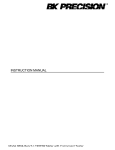
LIST OF PRODUCTS
*
*
*
*
*
*
*
*
*
*
*
*
*
*
*
*
*
*
*
*
*
*
*
*
*
*
*
*
Digital Multimeter
Digital AC & AC/DC Clampmeter
AC Clamp Adaptor
AC/DC Current Adaptor
Transistorised Electronic Analog & Digital Insulation
Resistance Testers(upto 10 KV)
Digital Sound Level Meter & Sound Level Calibrator
Digital contact & Non-contact Type Tachometer
Digital Non-contact (infrared) Thermometer &
Portable Infrared Calibrator
Thermo Hygrometer / Anemometer
Digital Absolute pressure meter
Wood, Paper & Grain Moisture Meter
Distance Meter & Network Cable Tester
Digital Hand Held Temperature Indicators
Digital Lux Meter
Thermal Imaging Camera
Power Factor Regulator
Maximum Demand Controller/Digital Power Meter
Earth Resistance Tester
Digital Panel Meters & DC Power Supplies
Digital Storage / Analog Storage Oscilloscope.
Coating Thickness Guage
Process Calibrators & Multifunction Calibrators
Gas Analysers & Waterproof Pen Testers
Frequency Counter / Function Generator
Phasing Sticks & High Voltage Detector
Transducer & Transmitter
Digital Milli Ohm Meter
Solar Power Meter
EMF/ELF Detector / RF Field Strength Meter
17, Bharat Industrial Estate, T. J. Road, Sewree (W),
Mumbai-400015. INDIA
Sales Direct: 24156638 Tel.:(022)2412 4540, 2418 1649 Fax:2414 9659
E-mail : [email protected], Website : www.kusamelectrical.com,
www.kusam-meco.co.in
Multi-Function LCR
MODEL KM 520B
OPERATION
MANUAL
Thank you for purchasing the multi-function LCR
meter. Please take a few minutes to browse through
this user manual before you begin to operate the
meter to ensure that you are fully familiarized with
how best to operate the meter as accurately and
safely as possible.
Overview
This multi-function LCR meter is a portable
instrument designed with microprocessor control
and low power consumption. It can measure 6 basic
parameters: inductance L, capacitance C, AC
resistance R, DC resistance DCR, dissipation factor
D and quality factor
Q. The instrument can easily communicate with PC
and realize remote control through USB interface.
With battery external power supply, the meter is
ideal for field and portable applications, such as
component inspection at fixed place, and immediate
measurement by maintenance personnel.
Cautions
=
This instrument can only be used in indoor.
=
Be sure to turn off the instrument when replacing
the battery or DC power adapter.
=
Although the instrument has a protection for shocks,
inputing dc voltage or current will still damage the
=
If the instrument is idle for more than 15 days
please take the batteries out.
=
Use AAA * 6 batteries. The instrument can not
work properly when low battery voltage indication
appears.
=
In order to ensure the measurement accuracy,
open / short calibration should be carried out again
after replacing the test fixtures.
=
Do not using the instrument under dusty, vibration,
direct sunlight and corrosion gas. environment
Introduction
Features
=
19,999/1,999 counts dual LCD display
=
Basic accuracy : 0.3% with resolution of 0.01%
=
Analog bar display
=
Measurement frequency up to 100KHz
=
Mini-USB interface
=
Auto LCR smart check and measurement
=
Sorting function
=
Relative measurement
=
Data hold,
=
Back light, full angle for LCD display
=
4-terminal measurement configuration
=
Automatic power off
=
Battery and external power supply
=
Battery voltage indication.
instrument. The capacitance requires completely
discharge before measuring.
1
2
Specifications
Specifications
DCR : DC resistance
Ls/Cs : series inductance /
Primary capacitance
Lp/Cp : parallel inductance /
capacitance
Parameters
q
: phase angle
D: dissipation factor
E
SR: equivalent series
Secondary resistance
Q : quality factor
RP: equivalent parallel
resistance
Frequency
100/120/1K/10K/100KHz
Display
Dual display + analog bar display
100/120Hz 20mH ~ 20KH
1KHz
2000m
H ~ 2000H
L
10K
200m
H ~ 20H
100KHz
20m
H ~ 200mH
100/120Hz 20nF ~ 20mF
2000pF ~ 2mF
1KHz
Measurement
200pF ~ 200m
F
C
10K
range
200pF ~ 20m
F
100KHz
~ 200MW
100/120Hz 200W
20W
~ 200MW
1KHz
R
20W
~ 20MW
10K
100KHz
20W
~ 2MW
DCR
200 ~ 200M
D/Q
0.001 ~ 1999
q 0.00° ~ ± 180.0°
Test Level
0.6 Vrms
Range mode Auto and Hold
Equivalent
Parallel and Series
circuit
3
Calibration function
Interface
Measurement speed
Open / Short
Mini - USB
Approx. 1.2 times/second
Measurement terminal 4-terminal
Basic accuracy
Power
0.3%
AAA*6 battery or external
power supply
Auto Power off
Operating
Environment
5 min (with batteries)
temperature 0°C ~ 40 °C
humidity
£
90%RH (40°C
no condensation
Storage temperature
-25°C ~ 50 °C
Impedance Accuracy Ae
The below - listed accuracies are guaranteed by the
meter with normal use under the operating
temperature of 18°C -28°C and relative humidity less
than 80%
4
Note :- All accuracy is guaranteed by proper ratio
resistor calibration and open/short calibration.
Explanation on Front Panel
1
If D > 0.1, the accuracy should be multiplied by
1+D2
2
ZC = 1 , if D << 0.1 in capacitance mode
2p
fc
ZL = 2p
f L, if D << 0.1 in inductance mode
3
8
7
6
SORTING PC LINK HOLD
Sub-display parameters accuracy :
Ae = impedanze (Z) accuracy.
11 10 9
4
FUNC.
SET UP SERPAL
DQESR
14 13 12
REL%
FREQ.
1
Definition : Q = D
5
CAL.
ENTER
15
Press 2 sec
Rp = ESR (or Rs) x (1+
1
)
D2
1) D value accuracy : De = ± Ae x (1+D)
INPUT
RX LX CX
GUARD
GUARD
16
LCUR
Hpot
Lpot
HCUR
2) ESR accuracy : Re = ± ZM x Ae (W
)
i.e., ZM = impedance calculated by 1
or 2p
fL
2p
fc
3. Phase angle q
accuracy : q
e = ± (180 / p
)
x Ae (deg)
Note :- D
:
Q
:
ESR :
Rp :
dissipation factor
quality factor
equivalent series resistance
equivalent series parallel
resistance
q:
phase angle
5
Figure 1
The front panel is shown as figure 1.
1) Mini USB interface :- Connect with PC, easily for
data transmission and management.
2) LCD :- Used for displaying the measuring results
and various symbols.
3)
key :- Used for putting ON or OFF the operating
power for the meter.
4) Func. Key :- When Func. key is pressed, the main
test mode could be selected sequentially: Auto-LCR
mode-Auto-L mode-Auto-C mode-Auto-R mode-DCR
mode-Auto-LCR mode.
6
5) CAL key :- Used to do OPEN/SHORT calibration.
6) SORTING key :- Press this key to enter into
sorting mode, which could help the user to make
a quick sort for a bunch of components.
7) PC LINK key :- Press this key to communicate
15) ENTER key :- In sorting mode, press ENTER key
to confirm the data modification.
16) Measurement terminal
The instrument has 4-terminal measurement
configuration, as shown in figure 2.
with PC.
GUARD
8) HOLD key :- Used to maintain the measurement
data unchanging, by pressing the key again it will
resume the measurement.
INPUT
Rx Lx Cx
GUARD
Grounding (shielding)
Excitation positive
terminal
LCUR
LPOT
H POT
HCUR
9) D/Q/ESR key :- In L/C measurement mode,
press the key to select parameters of D/Q/q
/ESR.
10) SETUP key :- When sorting mode is active, press
SETUP key to modify the reference value, range
and the tolerance setting sequentially.
Measurement positive terminal
Measurement negative terminal
Excitation negative terminal
Figure-2
Understanding Display Screen
11) SER/PAL key :- Used to select series and
parallel mode.
12) FREQ key :- Press FREQ key to select five
different test frequencies in turn : 100/120/1K/
10K/100KHz
13) REL% key :- Press REL% key to enter into
relative measurement mode. In auto LCR mode,
this key is not available.
14)
key :- By pressing this key for once, the backlight
of the LCD screen will be turn ON and after 60
seconds the meter will automatically turn off the
backlight. It is also possible to turn off the backlight by
pressing this key before the 60 seconds.
7
Figure-3
LCD screen is shown as in Figure 3, with its every
symbol's meaning shown as in the Table 1:
8
NO. MEANING
NO. MEANING
1
Auto power off indication
2
Data hold
3
Auto mode indication
4
Auto LCR mode indication
11 Sub-display
12 Analog bar indication
13 The meter is in the data transmission mode.
14 battery indication (with battery supply)
5
Range indication
6
Relative Measurement mode
15 Frequency indication
16 Tolerance range
7
Main-display
17 Sorting mode indication
8
Unit for main parameters
18 External power supply
9
Secondary parameters
19 Open/Short calibration mode indication
10 Unit for secondary parameters 20 Primary parameters
Operating instruction
Power on the meter
Press
key to turn ON the power. The default mode is
AUTO LCR smart mode and the default test frequency
is 1kHz. When
key is pressed during power-on
mode, the instrument will enter power-off mode. The
LCD will show the "OFF" state before power off.
Function Descriptions
1) Parameters setting
Press FUNC. key to select the following parameters
sequentially : AUTO LCR, L-Q, C-D, R, DCR.
Parameter
AUTO-LCR
L-Q
C-D
R
DCR
MEANING
Auto LCR smart mode
Inductance measurement, the parameter
on sub-display is quality factor Q
Capacitance measurement, the parameter
on sub-display is dissipation factor D.
Resistance measurement
DC resistance measurement mode
9
L/C/R measurement readings can be positive or
negative. In C-D measurement, If the main parameter
is "-", the actual component being tested is inductive;
In L - Q measurement, if the main parameter is "-", the
actual component being tested is capacitive;
Theoretically, R is positive, in some cases, R is "-",
which may be calibration error, please re-calibrate the
instrument.
2. Auto LCR smart Mode
The default test mode is Auto LCR mode which could
check the type of impedance smartly.
If I q
I < 11°, the Auto - R mode is selected. The
parameter on sub - display is q
.
If q
> 11°, the Auto - L mode is selected. The
parameter on sub - display is Q.
If q
< -11°, the Auto - C mode is selected. The
parameter on sub - display is D.
If the C < 5pF, the parameter on sub-display is parallel
resistance Rp.
Note : In order to avoid damaging the instrument,
the capacitance requires discharge before
measuring.
3. Frequency setting
Press FREQ key to select frequency value : 100/120/
1K/10K/100KHz. The LCR impedance scale ranges
are depended on the test frequency.
4. Data Hold
Press this key to hold the measurement data and
press it again to resume the measurement.
10
5. Relative mode
During relative measurement the meter remembers
the current readings on primary display (called
initial value) when pressing the REL% key, and
"REL" symbol appears on LCD. The secondary
display will show the percentage of relative value
REL%
b) When using LCUR / LPOT / HPOT /HCUR terminals insert
the black and red testing lines with alligator clip into
the "LCUR "," LPOT ",terminal and " HCUR ", "HPOT terminal
respectively. (shown in figure 5).
GUARD
LCUR
INPUT
Rx Lx Cx
LPOT
H POT
GUARD
GUARD
HCUR
LCUR
INPUT
Rx Lx Cx
LPOT
H POT
GUARD
HCUR
The REL% = (present value - initial value) / initial
value * 100%.
Press REL% key again to show the current
readings on primary display and the "REL" symbol
will be blinking. The percentage range is from
-99.9% ~ 99.9% when the present value is larger
than double of initial value, the "OL%" indication
will be shown on the secondary display.
During relative measurement, analog bar is
always indicating the present measurement
value but not the relative value.
6. Open / Short calibration
1) Press CAL key larger than 2 seconds to start the
open / short calibration procedure.
2) In open calibration mode, the secondary display
will show "Open". There are two ways for open
state input:
Figure 4
Figure 5
3) Press CAL key and the 30-second countdown
will be shown on LCD panels. If the open
calibration is finished, the PASS or FAIL symbol
will be shown on the primary display. Press
CAL key again to save the calibration data
and enter into the short calibration mode.
4) In short calibration mode, the secondary
display will show "Srt". There are two ways for
short state input:
a) When using square terminals, insert the short
soket to the square terminal and make
LCUR / LPOT / HPOT /HCUR terminals hang in the air
(shown in figure 6);
a) When using square terminals, the square terminals
and LCUR / LPOT / HPOT /HCUR terminals hang in the air
(shown in figure 4);
b) When using LCUR / LPOT / HPOT / HCUR terminalsinsert
the black and red testing lines with alligator clip
into the " LCUR"," LPOT",terminal and " HCUR ", "HPOT".
terminal respectively. Connect the mouth of clips
(shown in figure 7).
11
12
7. Equivalent Circuit
SHORT
GUARD
LCUR
GUARD
LPOT
H POT
GUARD
HCUR
LCUR
Figure 6
INPUT
Rx Lx Cx
LPOT
GUARD
H POT
HCUR
Figure 7
5) Press CAL key and the 30-second countdown
will be shown on LCD panels. If the short calibration
is finished, the PASS or FAIL symbol will be shown on
the primary display. Press CAL key again to save
the calibration data.
Note: 1) To get the better accuracy, the open / short
calibration should be done before measurement.
2) The purpose of open / short calibration is to
reduce the parasitic effect of the test fixture.
3) Open or short circuit, is selected automatically
according to the measurement terminal.
4) In short calibration, there may be FAIL situations,
which may be caused by not using the low
resistance short line or unreliable contact, please
try again after reliable short - circuit
When any L/C/R functional mode is selected, the
default measurement in series or parallel mode is
auto selected and the AUTO segment will be shown
on LCD display. It depends on the total equivalent
impedance measured.
If the impedance is larger than 10KW
, parallel mode
is set and Lp/Cp/Rp is shown on the display.
If it is less than 10KW
, series mode is set and Ls/Cs
/Rs is shown on the display. When SEL/PAL key is
pressed, the impedance measurement will be set in
series mode on in parallel mode sequentially.
Note :- The actual capacitance, inductance and
resistance is not ideal component of pure reactance
and pure resistance. Usually the resistance and
reactance exist simultaneously. A practical impedance
can be simulate by the ideal resistors and ideal
reactor (inductor or capacitor) in series or parallel
form.
8. Sorting mode
The sorting mode could help the user to make a
quick sort for a bunch of components. The setting
step as following:
1) Accordings to the component type, press FUNC,
key to select L, C or R measurement mode.
2) Insert the standard component into the input
therminal, Press SORTING key to enter into the
sorting mode and the "Sorting" symbol appears on
LCD. If the LCD reading is OL or less than 200
counts, the SORTING key is not available.
13
14
3) When sorting mode is active, press SETUP key
to modify the range, reference value and the
tolerance settings sequentially.
4) "Range" symbol is flashing when setting the
range. Press D/Q/ESR ( ) key to shift the decimal
point, unit to left and press SER/PAL (
) key to
right. Press ENTER key to confirm and enter into
the reference value setting mode automatically. At
this time, "Range" symbol disappear.
5) When setting the reference value, press D/Q/ESR
( ) key and SER/PAL ( ) key to shift the bit to left
and right respectively. Press PCLINK ( ) key and
REL % ( ) key to make the digit +1 or -1. The
flashing bit is the current setting bit. The reference
value setting is available from 20 to 1999 counts.
Press ENTER key to confirm and enter into the
tolerance setting mode automatically.
6) When setting the tolerance, press D/Q/ESR ( )
key & SER/PAL key to select tolerance range :
± 0.25% ± 0.5% ±1% ±2% ±5% ±10%
±20%
± 80%-20%. The default tolerance is
±1%. Press ENTER key to confirm.
7) After setting the parameters, remove the
standard component and insert the component
to be measured. If the impedance measured
does not exceed tolerance range, the primary
display will show "PASS", otherwise show
"FAIL". The current measurement result will be
shown on the secondary display.
15
8) Press SORTING key again to exit the sorting mode.
Note: In AUTO LCR mode, the SORTING key is
not available.
9. PC-LINK mode
Press PCLINK key "USB" symbol appear on
LCD. Connect the instrument to PC through
USB interface, and the measured data can be
recorded, analyzed, processed and printed by
PC. Press PCLINK key again to cancel the data
transmission. Then USB symbol disappears.
Due to the power consumption in data
transmission, please exit USB mode when there
is no need to transmit data.
Operating step
1.Inductance measurement
1) Turn on the power.
2) There are two ways for inductance input:
a. Insert the inductance to be measured into the
input terminal directly (shown in figure-8);
b. Connect the alligator clips to the ends of the
inductance to be measured (shown in figure-9).
3) The default test mode is Auto LCR mode, the
inductance value will be shown on primary
display and the quality factor Q will shown on
secondary display. In Auto LCR mode, the D/Q/
ESR key, SEL / PAL key, SORTING key and
REL% key are not available
16
4) Press FUNC. key to select Auto-L-mode. The
primary LCD display will show the quality factor Q.
The equivalent resistance ESR/Rp, phase angle q
or dissipation factor D can also be shown by
pressing the D/Q/ESR key.
5) Press FREQ key to select frequency value: 100/
120 /1K/10K/100KHz.
6) Press SER/PAL key to select series or parallel mode.
GUARD
LCUR
INPUT
Rx Lx Cx
LPOT
H POT
GUARD
GUARD
HCUR
LCUR
INPUT
Rx Lx Cx
LPOT
GUARD
H POT
HCUR
4) The default test mode is Auto LCR mode, the
capacitance value will be shown on primary display
and the dissipation factor D will be show on secondary
display. In Auto LCR mode, the D/Q/ESR key, SEL/PAL
key, SORTING key and REL% key are not available.
5) Press FUNC. key twice to select Auto-C mode.
The primary LCD display will show the capacitance
value. The secondary LCD display will show the
dissipation factor D. The quality factor Q, equivalent
resistance ESR/Rp or phase angel q
can also be
shown by pressing the D/Q/ESR key.
6) Press FREQ key to select frequency value: 100/
120 /1K/10K/100KHz.
7) Press SER/PAL key to select series or parallel mode.
Figure 8
Figure 9
2. Capacitance measurement
1) Turn on the power.
2) If voltage exists in the capacit or connect the two
ends of the capacitors for a short time to discharge.
3) There are two ways for capacitance input:
a. Insert the positive polarity of capacitance into the
positive terminal and its negative polarity into the
negative terminal (shown in figure 10);
b. Insert the black and red testing lines with alligator
clip into the "LCUR", "LPOT", terminals and "HCUR", "HPOT",
terminal respectively. Connect the alligator clips to
the ends of capacitance corresponding to its polarity
(shown in the figure 11).
Note :- 1) When Auto-LCR mode is active, the secondary
parameter will show the equivalent resistance
in parallel mode (Rp) to replace the D factor if
the C measured value is less than 5pF.
2) In order to avoid damaging the instrument,
the capacitance requires discharge before
measuring
GUARD
LCUR
INPUT
Rx Lx Cx
LPOT
H POT
GUARD
GUARD
HCUR
LCUR
Figure 10
17
INPUT
Rx Lx Cx
LPOT
GUARD
H POT
Figure 11
18
HCUR
3. Resistance measurement
1) Turn on the power.
2) There are two ways for resistance input:
a. Insert the resistance to be measured into the input
terminal directly (shown in figure-12);
b. Connect the alligator clips to the ends of the
resistance to be measured (shown in figure-13).
Note : The phase angle q
will show on secondary
display only in Auto-LCR mode. During
Auto-R mode or DCR mode, the secondary
parameter is not available.
GUARD
LCUR
3) The default test mode is Auto LCR mode, the
resistance value will be shown on primary display
and the phase angle q
will be shown on
secondary display. In Auto LCR mode, the D/Q/
ESR key, SEL/PAL key, SORTING key and REL
% key are not available
4) Press FUNC. key three times to select Auto-R
(ACR) mode, The primary LCD display will
show the resistance value. The secondary
parameter is omitted and the D/Q/ESR key. is not
available.
5) Press FREQ key to select frequency value:
100/120 /1K/10K/100KHz.
6) Press SER / PAL key to select series or parallel
mode.
7) Press FUNC. key four times to select DCR mode.
The primary LCD display will show the resistance
value. The secondary parameter is omitted and
the D/Q/ESR key, SEL/PAL key and FREQ key
are not available.
GUARD
INPUT
Rx Lx Cx
LPOT
H POT
GUARD
HCUR
LCUR
Figure 12
INPUT
Rx Lx Cx
GUARD
H POT
LPOT
Figure 13
To use Adapter (Under external power adapter,
the automatic power off function is not available).
Connecting the power adapter:
1) Connect the AC power cord to the AC-DC
converter
2) Plug the AC power cord into an electrical outlet
(100V-240V).
3) Plug the DC power plug of the convertor into DC
power socket of the meter
DC power
DC power
Socket
Plug
AC-DC
Converter.
AC/DC adapter information:
Input : 100V-240VAC, 50-60Hz 1.8A
Output : DC 12V
2A MAX
Polarity : +
-
19
HCUR
20
AC power
Cord
WARNING:
1) Please use the original AC power adapter, using
other AC power adapter may damage your
instrument.
2) The AC power adapter can only be used indoors.
3) Please plug the AC power cord into an electrical
outlet first and then firmly insert DC plug into DC
input end in the right of the meter. When unplugged,
firstly pull out the DC plug perpendicular to DC input
end and then unplug the AC plug from the electrical
outlet.
4) Do not use the AC power adapter in other equipment
except this instrument.
5) In use, it is a normal phenomenon that the AC power
adapter will be hot.
6) Do not demolish the AC power adapter. Otherwise, it
may be dangerous
7) Do not use the AC power adapter in a high
temperature or wet place.
8) Please make the AC power adapter avoid a strong
bump.
9) It is normal when the AC power adapter make
some noise in use.
Replacing the Battery :- Please change the
battery when the battery symbol
is less than
one segment.
Turn off the power of the instrument. When you
change the battery, and screw off the breechblock
on the battery cabinet cover, then take off it and
replace with fresh battery.
ACCESSORIES
=
User manual.
=
AAA batteries
=
Shielding clip line
=
Kelvin 4-terminal measure line
=
Short socket
=
USB line (USB model only)
=
PC-Link software CD
(USB model only)
If there are some changes in accessories, please
refer to the real products as standard.
Note : To get the better accuracy, when using
LCUR/LPOT/ HPOT/HCUR/ terminal measured with the
alligator clip-testing lines, Please insert the open
soket to the square terminals (shown in figure 14).
OPEN
GUARD
GUARD
MAINTENANCE
Cleaning :- Periodically wipe the case with a damp
cloth do not use abrasives or solvents.
Calibration :- Calibrate your instrument once a year
to ensure that it performs according to its
specifications.
21
One piece
Six piece
One piece
One piece
One piece
One piece
One piece
LCUR
LPOT
H POT
Figure 14
22
HCUR
WARRANTY
MUMBAI
Each “KUSAM-MECO” product is warranted to be free from
defects in material and workmanship under normal use &
TEST CERTIFICATE
service.
The warranty period is
one year (12 months) and
begins from the date of despatch of goods. In case any defect
occurs in functioning of the instrument, under proper use, within
Multifunction LCR
the warranty period, the same will be rectified by us free of
charges, provided the to and fro freight charges are borne by
you.
This Test Certificate warrantees that
the product has been inspected and
tested in accordance with the published
specifications.
This warranty extends only to the original buyer or end-user
customer of a “KUSAM-MECO” authorized dealer.
This warranty does not apply for damaged Ic’s, burnt PCB's,
fuses, disposable batteries, carrying case, electrodes probes,
cables or to any product which in “KUSAM-MECO’s” opinion, has
been misused, altered, neglected, contaminated or damaged by
accident or abnormal conditions of operation or handling.
520B
MODEL NO. KM
__________
“KUSAM-MECO” authorized dealer shall extend this warranty on
new and unused products to end-user customers only but have no
authority to extend a greater or different warranty on behalf of
SERIAL NO. ___________
“KUSAM-MECO”.
“KUSAM-MECO’s” warranty obligation is limited, at option, free of
charge repair, or replacement of a defective product which is
DATE: ___________
returned to a “KUSAM-MECO” authorized service center within
the warranty period.
THIS WARRANTY IS BUYER’S SOLE AND EXCLUSIVE REMEDY AND IS IN
LIEU OF ALL OTHER WARRANTIES, EXPRESS OR IMPLIED, INCLUDING
ISO 9001
REGISTERED
QC
BUT NOT LIMITED TO ANY IMPLIED WARRANTY OF MERCHANTABILITY
KUSAM-MECO
OR FITNESS FOR A PARTICULAR PURPOSE. “KUSAM-MECO” SHALL
PASS
NOT BE LIABLE FOR ANY SPECIAL, INDIRECT, INCIDENTAL OR
CONSEQUENTIAL DAMAGES OR LOSSES, INCLUDING LOSS OF DATA,
ARISING FROM ANY CAUSE WHATSOEVER.
All transaction are subject to Mumbai Jurisdiction.
23
24