1
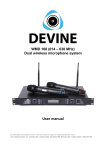
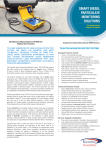
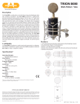
BM-1000
Professional studio recording microphone
User manual
Any information and illustrations shown in this user manual are subject to change without further notice.
User manual version: 1.0 Creation date + author initials: 27-01-2014 RV Revision date + author initials: 27-01-2014 RV
Introduction
Thank you for purchasing this Devine BM-1000 broadcasting and recording microphone. Before you unpack
all the received items, carefully read this manual to become familiar with the functions of the microphone.
Also check the contents of the box to make sure all necessary parts are included. If the microphone fails to
operate properly, or if you have any problems while using it, disconnect it and contact your local dealer for
more information and help.
Any information and illustrations shown in this user manual are subject to change without further notice.
User manual version: 1.0 Creation date + author initials: 27-01-2014 RV Revision date + author initials: 27-01-2014 RV
Box contents
Box contents:
1x Devine BM-1000 microphone
1x metal popshield
1x shockmount
1x XLR – 3.5 mm jack cable for direct computer recording
Unit and accessory inspection
- If the unit is not going to be used for a longer period of time, disconnect it and store it in a dust-free
environment.
- Always check the unit for possible damage before use. If you suspect that something is wrong with the unit,
do not connect it! When you suspect that your unit is broken or damaged, contact your local dealer or a
certified technician to inspect the unit.
Note: Illustrations shown in this manual may vary from the actual product.
Any information and illustrations shown in this user manual are subject to change without further notice.
User manual version: 1.0 Creation date + author initials: 27-01-2014 RV Revision date + author initials: 27-01-2014 RV
Use of the microphone
The Devine BM-1000 studio microphone is suitable for most recording applications in your studio.
The Devine BM-1000 has an unidirectional (cardioid) polar pattern. This is the most used polar pattern for
most vocal and instrument recording applications. Most of the sound is captured at the front of the
microphone, while reducing pickup of sound at the sides and especially the rear. This is the best choice
when you use (studio)monitors directly behind the microphone, to avoid feedback problems when using live
monitoring.
The BM-1000 microphone is equipped with a special capsule with pure aluminum plating (patented), to
improve the sound to a warm, pleasant character.
The polar pattern and frequency response of the microphone are visible in the figures below:
The BM-1000 microphone has a slight boost in the higher frequencies (around 10 kHz) for clear vocal
recording.
IMPORTANT: Phantom power
The BM-1000 microphone is equipped with a dual working system, as described below:
1. Dynamic mode (5V mode). This mode is for use with mixers and audio interfaces which do not have the
ability to supply phantom power.
+ No separate phantom power needed
- Less dynamic capturing of sound, quality loss
2. Condenser mode (48V mode). This mode is for use with mixers and audio interfaces which are able to
supply phantom power, or for use with external phantom power supplies.
+ Better sound quality and more dynamic sound
- requires +48V phantom power to work.
To change the status of the microphone, an internal switch is provided to change settings.
Pressed in = Phantom power mode
Pressed out = Dynamic mode
Do not change the status during use, as this might damage your microphone and speaker system (as the
switch creates a short circuit during switching). This may permanently damage your speaker system and
doing so will void any warranty. Always unplug the microphone when switching modes.
To switch to a different mode, loosen the bottom cap of the microphone (bottom chrome piece, surrounding
the XLR connector.
After this, detach the black body housing while holding the head of the microphone firmly. You will see all
internal components of the microphone and the white switch which is used to change the setting. Press the
switch gently and select the desired working mode. After this, re-assemble the microphone in reverse order.
Any information and illustrations shown in this user manual are subject to change without further notice.
User manual version: 1.0 Creation date + author initials: 27-01-2014 RV Revision date + author initials: 27-01-2014 RV
Close-up of the mode switch, to change from dynamic mode
condenser mode and vice versa.
Protect your microphone:
This Devine microphone is equipped with very sensitive electronics to provide optimal audio performance.
Make sure the microphone is not exposed to severe shocks, collision, drops from high altitude or any
situations that may cause permanent damage. Improper use of the microphone is not covered by warranty.
Always transport the microphone in the original package, or in a flightcase with proper foam inlay.
Transporting the microphone without proper protection may cause permanent damage and will not be
covered by warranty.
Positioning and using the included accessories:
The BM-1000 includes a shock mount and metal pop filter for optimal audio performance. Devine
recommends to always use the included shock mount, to prevent audio distortion and background or
handling noise. The metal pop screen is optional and is mostly used when recording vocals. The windscreen
breaks up airflow caused by vocal expressions, which prevents distortion.
Connect your microphone to a mixer or audio interface:
This microphone comes with a XLR – 3.5mm TRS jack cable for direct connection with a computer
microphone input. It is also possible to use a 3-pin XLR cable for connection with your mixer or audiointerface (XLR-XLR cable not included). It is recommended to check the settings on your audio equipment
before connecting the microphone, regardless of the selected working mode. Check your equipment for the
following settings:
Mixer/Audio interface:
- Gain set to the 0-point (in the most final counter-clockwise position)
- Compression/lowcut settings positioned in the off or most neutral position
- EQ settings on the most neutral position
- Pan/Balance settings on the most neutral position
- Volume fader or potentiometer set to the lowest possible position
- Phantom power in the ‘on’ position when used in this mode (mostly a button per channel, or a group of
channels)
Microphone:
- Steady positioning on a microphone stand (sold separately), with the included shock mount
- Make sure the audio source (vocalist or instrument) is positioned as close as possible to the microphone
After you checked the settings above, you may start recording the audio source. Placing the audio source as
near to the microphone as possible, provides the best audio quality and grants you the ability to reduce
overall gain settings, which prevents audio feedback and noise.
Turn the volume parameter (potentiometer or fader) on the ‘0 dB’ position for the best audio performance and
slowly increase the gain, until slight clipping (mostly indicated with a (LED) VU meter or LED) or distortion is
noticed.
Placement on a microphone stand or boom arm
The shockmount of the BM-500 microphone is equipped with a 5/8” thread, suitable for most microphone
stands. If your microphone stand has 3/8” thread, adapters can be purchased separately. For easy
positioning, mount the shockmount with the thread mount before mounting the microphone.
Any information and illustrations shown in this user manual are subject to change without further notice.
User manual version: 1.0 Creation date + author initials: 27-01-2014 RV Revision date + author initials: 27-01-2014 RV
Troubleshooting
Problem
Possible Cause
Solution
No sound, or very low sound
signal
No phantom power
Connect or activate phantom
power supply
Volume set too low
Increase incoming volume and
gain on your mixer, interface or
other sound processing device
Microphone positioned too far
away
Place the microphone closer to the
sound source
Rattling and cracking sounds
Moist inside the microphone
Let the microphone dry on room
temperature and avoid use of the
microphone in humid or moist
environments. Do not let the
microphone come in contact with
water or liquids.
Loud high frequencies coming
from the speakers
Microphone positioned too close to Move the microphone further away
the speakers, which causes
from the speakers, or change the
feedback
position to prevent the microphone
to be aimed directly at the
speakers.
Interruptance of the microphone
signal
Loose cable or broken cable
Check if the cable is plugged into
the microphone correctly. If that
does not solve the problem, try to
change the cable.
Distortion and/or noise in the
captured sound
Too much airflow caused by vocal
airflows
Use the pop screen (included)
Too much airflow caused by wind
(outdoor use)
Use a windscreen (sold
separately)
Any information and illustrations shown in this user manual are subject to change without further notice.
User manual version: 1.0 Creation date + author initials: 27-01-2014 RV Revision date + author initials: 27-01-2014 RV
Technical specifications
- small diaphragm condenser recording microphone
- cardioid polar pattern
- high sensitivity for clear and detailed recordings
- low self noise
- wide dynamic range
- patended pure aluminum-plating diaphragm
- solid construction, modern appeal
- reflective nickel plated parts for a stylish appearance in every setup
Details:
- frequency response: 20 Hz - 20 kHz
- sensitivity: -37 dB (+/- 2 dB) at 0dB = 1V/Pa on 1 kHz
- output impedance: 200 Ohms ( +/- 30%) on 1 kHz
- load impedance: ≥ 1000 Ohms
- self noise level: 16 dBA
- max. SPL: 136 dB ( at 1 kHz, 1% T.H.D.)
- S/N ratio: 78 dB
- power requirements: 5V or 48V phantom power (switch)
Physical:
– dimensions: 50 x 50 x 230 mm (microphone without shock mount)
– weight: 0.455 kg
Included accessories:
- nickel plated shock mount
- metal pop filter with mounting hardware
- XLR to 3.5 mm jack cable (2.5 m)
Any information and illustrations shown in this user manual are subject to change without further notice.
User manual version: 1.0 Creation date + author initials: 27-01-2014 RV Revision date + author initials: 27-01-2014 RV