1
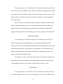
Feasibility Study For Teaching Geometry and Other Topics
Using Three-Dimensional Printers
Elizabeth Ann Slavkovsky
A Thesis in the Field of Mathematics for Teaching
for the Degree of Master of Liberal Arts in Extension Studies
Harvard University
October 2012
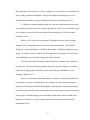
Abstract
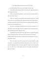
Since 2003, 3D printer technology has shown explosive growth, and has become significantly less expensive and more available. 3D printers at a hobbyist level are available for as little as $550, putting them in reach of individuals and schools. In addition, there are many “pay by the part” 3D printing services available to anyone who can design in three dimensions. 3D graphics programs are also widely available; where 10 years ago few could afford the technology to design in three dimensions, now anyone with a computer can download Google SketchUp or Blender for free. Many jobs now require more 3D skills, including medical, mining, video game design, and countless other fields. Because of this, the 3D printer has found its way into the classroom, particularly for STEM (science, technology, engineering, and math) programs in all grade levels. However, most of these programs focus mainly on the design and engineering possibilities for students. This thesis project was to explore the difficulty and benefits of the technology in the mathematics classroom. For this thesis project we researched the technology available and purchased a hobby-‐level 3D printer to see how well it might work for someone without extensive technology background. We sent designed parts away. In addition, we tried out Google SketchUp, Blender, Mathematica, and other programs for designing parts. We came up with several lessons and demos around the printer design. The printer was demonstrated to a group of Harvard freshman for their calculus class, and many of them stayed after class to watch the printer work and ask questions. As a result of this project we conclude that anyone can use the printer technology in the classroom, but there are still many challenges. If a teacher chooses to purchase a printer for the classroom, the technology is still in hobbyist phase, and requires time to assemble and calibrate. This tried the patience of the author and would probably be difficult for many teachers. However, the technology continues to improve. There are also cost considerations. In terms of the overall goals for the thesis project, the initial focus on the pure mathematics of basic geometric shapes was not as interesting as some later experiments. It does not take a lot of time to learn to design a cube, sphere, or cone, and then print them out. Teachers, students, and regular passersby always wanted to know what else you could do with the printer. In response, we designed some more complex models. The mathematics behind them is suitable in the mathematics classroom at all levels. It is, for example, interesting to create solids of revolution. By the end of the thesis, the author started to see where learning to teach and design similar shapes to discuss volume comparison starts to be both interesting and accessible. The project took a good deal of patience and imagination, but was fully immersive and generated a considerable amount of curiosity.
Author’s Biographical Sketch
Liz Slavkovsky is a technical writer with an interest in helping students visualize
difficult concepts. She currently writes for post office software, and has previously
worked in the pharmaceutical, finance, and video game industries. She enjoys playing
violin in chamber music groups, swimming in Walden Pond, and vegetable gardening.
v
Acknowledgements
This was a wonderful project, full of little corners. Thanks especially to Oliver
Knill, whose enthusiasm and encouragement really helped make each week of this
project full of new challenges and experiments. Thanks to his Math 1a class for being so
enthusiastic about the printer.
Thanks to Andy Engelward, who helped me though the planning phases of this
project and supported me when I abruptly changed topics.
I value the input of my Dad, Tom Slavkovsky, who teaches math and physics and
who pointed out that this kind of thinking would be very helpful in a classroom.
Thanks to the Artisan Asylum for the interesting world they’ve built there and
hands-on experience with a commercial-grade printer. Thanks to X-Object who worked
with me on the UP! 3D printer.
And thanks to my fiancé Max Considine, who helped me set up my little home
manufacturing shop, and dealt with the frustration when things didn’t quite go as
expected.
vi
Table of Contents
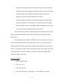
Author’s Biographical Sketch ............................................................................................. v Acknowledgements ............................................................................................................ vi List of Figures ................................................................................................................ xi Chapter 1 Introduction ........................................................................................................ 1 History of 3D Printing .................................................................................................... 8 Basic Terminology ........................................................................................................ 11 The Printouts ................................................................................................................. 11 Potential Impact ............................................................................................................ 13 Examples of Where Printers Are Used ......................................................................... 14 3D Printers in the Classroom ........................................................................................ 18 Chapter 2 Hobbyist 3D Printers and Printing Services ..................................................... 19 The UP! 3D Printer ....................................................................................................... 19 Setting Up the UP! 3D Printer ...................................................................................... 21 Installing the UP! 3D printer. .................................................................................... 21 Other Inexpensive 3D Printers ...................................................................................... 25 CNC Machines .............................................................................................................. 27 Third-Party Printing Services ....................................................................................... 27 Printers in Your Neighborhood..................................................................................... 29 Commercial Printers ..................................................................................................... 30 Chapter 3 3D Graphics and Design Tools ........................................................................ 32 vii
Google SketchUp .......................................................................................................... 32 Mathematica.................................................................................................................. 34 Blender ...................................................................................................................... 34 OpenSCAD ................................................................................................................... 35 AdMesh ......................................................................................................................... 35 MeshLab ....................................................................................................................... 36 Other Tools ................................................................................................................... 36 IPad and IPhone Applications....................................................................................... 37 3D Printer Software ...................................................................................................... 37 3D Scanners .................................................................................................................. 38 Chapter 4 Projects for the 3D printer ................................................................................ 39 Working with Google SketchUp................................................................................... 42 Change the template in Google SketchUp ................................................................ 42 Designing and Printing Simple Shapes in Google Sketchup .................................... 43 Designing and Printing Simple Shapes in Mathematica ........................................... 46 Design a Pyramid in Google SketchUp .................................................................... 48 Design a Cylinder in Google SketchUp .................................................................... 51 Draw a Cone in Google SketchUp ............................................................................ 52 Odd-Shaped Base ...................................................................................................... 54 Reverse Volume and Surface Area Exercises ........................................................... 56 Chapter 5 Exploring Archimedes...................................................................................... 58 Estimating the Area of a Circle ................................................................................. 58 Understanding Area Versus Volume ........................................................................ 61 viii
Estimating the Size of a Cone ................................................................................... 61 The Volume of the Tetrahedron and Pyramid .......................................................... 63 Design Archimedes’ Tombstone in Google SketchUp ............................................. 66 The Archimedes Tombstone Hands-On Demo ......................................................... 73 The Cork Problem as Related to Archimedes’ Techniques ...................................... 75 Cork Problems and Solutions .................................................................................... 86 The Intersection of Two Cylinders ........................................................................... 87 Advanced Steinmetz Solid Exercises ........................................................................ 92 Archimedes Hoof ...................................................................................................... 95 Chapter 6 Other Problems ............................................................................................... 100 Soddy’s Hexlet ........................................................................................................ 100 Frustum Problems ................................................................................................... 105 Klein Bottles ........................................................................................................... 106 3D Fractals .............................................................................................................. 106 Peano Curve ............................................................................................................ 108 Superformula and Supershapes ............................................................................... 109 Archimedean Solids ................................................................................................ 111 Reuleaux Tetrahedron ............................................................................................. 112 Galton Board ........................................................................................................... 113 Chapter 7 Current 3D Printer Use in Schools ................................................................. 114 Teaching in 3D............................................................................................................ 116 Chapter 8 Teaching Results ............................................................................................ 118 Overall Impressions .................................................................................................... 118 ix
Send-Away Assignments ............................................................................................ 119 Printer Demonstrations and Custom Models .............................................................. 120 Reception in the Classroom ........................................................................................ 121 Further Classroom Work ............................................................................................ 123 Chapter 9 Summary and Conclusions ............................................................................. 125 Guidelines for Designing in 3D .................................................................................. 125 Working with 3D Printers ........................................................................................... 126 Working with 3D Printing Services ............................................................................ 127 Conclusions ................................................................................................................. 127 Appendix 1 Glossary....................................................................................................... 129 Previous Technologies ................................................................................................ 129 Current Technologies .................................................................................................. 130 Appendix 2 Mathematica for Archimedes’ Tombstone Hands-On Demo ..................... 134 References ....................................................................................................................... 135 x
List of Figures
Figure 1: Archimedes screw ............................................................................................... 1 Figure 2: A 3D-printed regular pyramid, designed by the author and printed by the
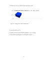
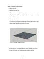
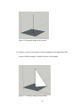
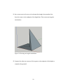
Shapeways service .............................................................................................................. 2 Figure 3: Irregular 3D pyramids ......................................................................................... 3 Figure 4: Dodecahedron from Thingiverse ......................................................................... 4 Figure 5: Folio 314 of Billingsley's edition of Euclid’s Elements ...................................... 5 Figure 6: Platonic solids dice .............................................................................................. 7 Figure 7: Glass bowl made from heated sand ................................................................... 15 Figure 8: Klein bottle opener ............................................................................................ 16 Figure 9: George Hart's 3D-printed visualization puzzle ................................................. 17 Figure 10 UP! 3D printer .................................................................................................. 20 Figure 11 Printed double dodecahedron ........................................................................... 41 Figure 12: Drawing a square in Google SketchUp ........................................................... 45 Figure 13: Using the Push/Pull tool to finish a cube in Google SketchUp ....................... 45 Figure 14: Creating a Blue Cuboid in Mathematica ......................................................... 47 Figure 15: Drawing diagonals on a square ....................................................................... 48 Figure 16: Setting the height of the pyramid .................................................................... 49 Figure 17: Creating a triangle in the pyramid ................................................................... 49 Figure 18: Drawing an irregular tetrahedron .................................................................... 50 Figure 19: A completed regular pyramid .......................................................................... 51 Figure 20: Completed cylinder ......................................................................................... 52 xi
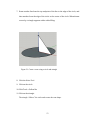
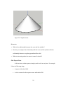
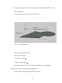
Figure 21: Create a cone using a circle and triangle ......................................................... 53 Figure 22: Completed cone ............................................................................................... 54 Figure 23: Odd-shaped base.............................................................................................. 55 Figure 24: Odd-shaped solid. ............................................................................................ 56 Figure 25: Cube surface area cut out ................................................................................ 57 Figure 26: Breaking a circle into triangles ........................................................................ 61 Figure 27: Tetrahedron ..................................................................................................... 62 Figure 28: Archimedes understood the relationship between the Pythagorean formula,
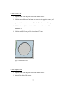
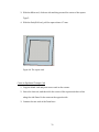
triangular numbers, and the volume of a pyramid and cube ............................................. 63 Figure 29:Irregular pyramid in Slavkovsky's Shapeways account ................................... 64 Figure 30: Three irregular pyramids ................................................................................. 65 Figure 31: The three contrasting pyramids create a cube ................................................. 65 Figure 32: Designs for the tetrahedron ............................................................................. 66 Figure 33: Circle above the cylinder ................................................................................. 69 Figure 34: Sphere above cylinder ..................................................................................... 70 Figure 35 Cylinder ............................................................................................................ 71 Figure 36 Completed sphere within cylinder in UP! 3D printing software ...................... 72 Figure 37: Archimedes Tombstone funnel demonstration................................................ 75 Figure 38: The blank card ................................................................................................. 76 Figure 39: The circle card ................................................................................................. 77 Figure 40: The square card ............................................................................................... 78 Figure 41: First line of triangle card ................................................................................. 79 Figure 42: Perpendicular ................................................................................................... 79 xii
Figure 43: Draw the final triangle. .................................................................................... 80 Figure 44: The final triangle. ............................................................................................ 81 Figure 45: Cork problem using the square and circle cards, along with a blank card ...... 82 Figure 46: Circle and square for the cork solution ........................................................... 83 Figure 47: Final solution to the cork problem .................................................................. 84 Figure 48: Cork problem solution in Mathematica ........................................................... 85 Figure 49: Printed cork problems ..................................................................................... 86 Figure 50: Printed cork solutions ...................................................................................... 86 Figure 51: Creating circles for the Steinmetz solid .......................................................... 88 Figure 52: First cylinder for the Steinmetz solid .............................................................. 89 Figure 53: Two cylinders for the Steinmetz solid ............................................................. 90 Figure 54: Removing material outside the intersection of cylinders ................................ 91 Figure 55: The Steinmetz solid, originally explored by Archimedes ............................... 92 Figure 56: Three cylinders intersecting ............................................................................ 93 Figure 57: Intersecting three cylinders ............................................................................. 94 Figure 58: Wireframe cube ............................................................................................... 95 Figure 59: Finding the center of a square. ........................................................................ 96 Figure 60: Creating a cylinder .......................................................................................... 97 Figure 61: Creating the hoof ............................................................................................. 98 Figure 62: Plane intersecting with cylinder ...................................................................... 99 Figure 63: Archimedes hoof ............................................................................................. 99 Figure 64: Soddy's Hexlet ............................................................................................... 100 Figure 65: Dupin cyclide through which the spheres rotate ........................................... 101 xiii
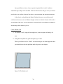
Figure 66: Create two concentric circles, with some number of circles fitting between the
two................................................................................................................................... 102 Figure 67: Mathematica depiction of Soddy's hexlet...................................................... 104 Figure 68: Soddy's Hexlet printout from Shapeways ..................................................... 104 Figure 69: Attempting to create circles between the inner and outer circles fails .......... 105 Figure 70:Frustrum problems ......................................................................................... 106 Figure 71: Klein bottle examples .................................................................................... 106 Figure 72: Mandelbulb .................................................................................................... 107 Figure 73: Menger sponge .............................................................................................. 108 Figure 74: Peano curve ................................................................................................... 109 Figure 75: Supershape example 1 ................................................................................... 110 Figure 76: Supershape example 2 ................................................................................... 110 Figure 77: Archimedean solids ....................................................................................... 111 Figure 78: Four spheres create the Reuleaux Tetrahedron ............................................. 112 Figure 80: Students constructing a 3D printer ................................................................ 115 Figure 81: The 3D printer in the classroom .................................................................... 123 xiv
Chapter 1 Introduction
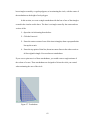
Geometry courses are highly visual, beginning with ruler and compass
constructions, comparing triangles, measuring circles, and making cutouts. There are
many activities for two-dimensional projects, starting with Euclid’s constructions and
moving through whatever a teacher can think of on paper. These help build intuition and
understanding of basic geometry (Fugita et al., 2004).
When students move from two-dimensional (2D) geometry to three-dimensional
geometry, options for working in 3D are often limited by materials or standard designs.
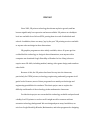
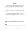
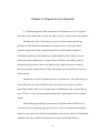
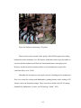
Mathematicians from Euclid to Archimedes to Newton and beyond have all worked to
use mathematics to communicate the 3D world, the one that is most directly around us.
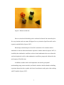
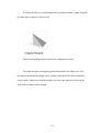
Figure 1: Archimedes screw
1
Archimedes was a great thinker in terms of 3D math, puzzling out complicated
proofs to problems or designing practical apparatus using mathematics. It is possible he
would have been a great fan of 3D printers. As part of this project, several problems that
Archimedes considered have been discussed and printed.
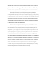
3D printers allow teachers and students to create models of what are traditionally
abstract concepts. From basic shapes in early geometry classes, such as cylinders,
spheres, cones, and cubes, to solids of revolution in calculus, to problems in topology, 3D
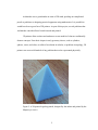
printers can create solid models of any problem that can be represented physically.
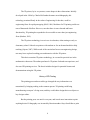
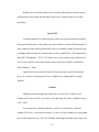
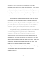
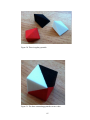
Figure 2: A 3D-printed regular pyramid, designed by the author and printed by the
Shapeways service
2
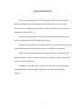
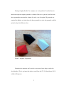
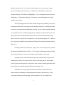
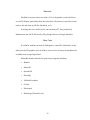
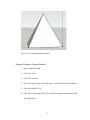
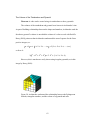
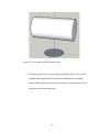
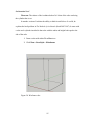
Printing is highly flexible. For example, one “cork problem” described later in
this thesis required a regular pyramid as a solution. However, as part of a proof to show
that a pyramid has one-third the volume of a cube, a set of irregular 3D pyramids was
required. In addition, to clearly show the three pyramids in a cube, the pyramids could be
printed or dyed in different colors.
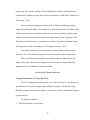
Figure 3: Irregular 3D pyramids
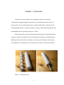
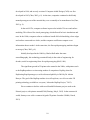
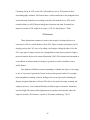
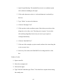
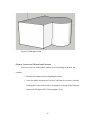
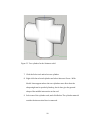
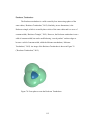
Sometimes the printouts can be used to re-envision a basic shape, such as the
dodecahedron. This is a printout the author created from the STL file that Adams (2011)
added to Thingiverse.
3
Figure 4: Dodecahedron from Thingiverse
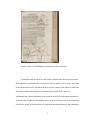
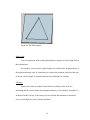
Educators have been using 3D models in educational materials for centuries. For
example, Sir Henry Billingsley’s English translations of Euclid’s The Elements included
folding “pop-ups” to help demonstrate the three-dimensional objects. The thesis author
first learned about this book from Edward Tufte, who writes books on how to
communicate data effectively using visual aids. In a seminar he passed this book around
as an example of a good publication for communicating mathematical concepts. Figure 5
shows an image of the pop-ups from Swetz and Katz (2012).
4
Figure 5: Folio 314 of Billingsley's edition of Euclid’s Elements
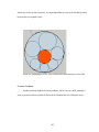
Archimedes built on Euclid’s work, and he considered his discoveries on certain
3D mathematics, particularly the two volumes of On the Sphere and Cylinder, to be some
of his greatest discoveries. He had the discovery of the volume of the sphere in relation to
that of the cylinder inscribed on his tombstone (Heath, 2002/1897). However,
Archimedes had a strong foundation in the practical world. He created many mechanical
inventions, for example, the Archimedes Screw, a device to carry water up an incline that
is still in use today. He did not, however, take these inventions seriously, and called them
5
“diversions of geometry at play” (Heath 2007/1897). However, it appears that he used his
understanding of center of mass to influence his understanding of the sphere and cylinder,
as outlined in The Method of Archimedes. The method he used foreshadows the
development of calculus, and is strongly related to physical understanding of shapes
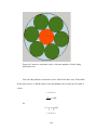
(Heath, 2007/1897).
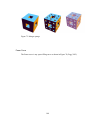
As a geometry student in 1993, the author of this thesis cut out, folded, and
awkwardly glued together many three-dimensional shapes. In courses at the Math for
Teaching program, she spent many an hour trying to mentally imagine the Platonic
solids, until she started modeling them out of clay and eventually bought a set of dice that
sufficed. One exercise included counting all faces, vertices, and edges to show:
F+V-E=2
Where:
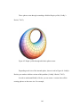
•
F = Faces •
V = Vertices •
E = Edges (“Euler’s Formula,” n.d.) This relationship is difficult to prove with the icosahedron or dodecahedron by using
mental rotations, but if one has numbered dice, keeping track becomes fairly trivial.
6
Figure 6: Platonic solids dice
However, this kind of modeling can be awkward or limited. One cannot buy dice
for every situation, and one cannot fold paper for every situation. Specific models can be
expensive and inflexible (Lipson, 2007).
Knowledge retention improves from 20% retention to 90% retention when a
student has a concrete rather than abstract experience with the material (Lipson, 2007). It
is unlikely that Archimedes would have achieved such mathematical success without his
work in the physical world, or that mathematics would have progressed without the ruler
and compass of Euclid’s time.
In addition, students with visual impairment can stand to gain spatial
understanding using concrete models, and females who have had less hands-on building
experience than males due to gender roles have been shown to make gains when working
with 3D models (Lipson, 2007).
7
The 3D printer, by its very nature, creates shapes in three dimensions. Initially
developed in the 1980s by Charles Hull under the name stereolithography, this
technology remained firmly in the realm of engineering for decades, useful to
engineering firms for rapid prototyping (Hull, 1986). Machines for 3D printing could cost
tens of thousands of dollars. However, now that there is more demand and better
functionality, 3D printing has expanded to be accessible to more than just engineering
firms (Bartlett, 2012).
The 3D printer technology is now in use in education, often starting as early as
elementary school. Schools use printers with students or for on-demand models to help
teaching (Lipson, 2007). While much of the curriculum focuses on engineering design,
not many have explored teaching pure mathematics with the 3D printer.
This thesis examines 3D printer technology, its cost and its practical use in the
mathematics classroom. The author purchased a 3D printer for hands-on experience, and
also used 3D printing services. The thesis includes designs for potential lessons and
demonstrations using the 3D printer.
History of 3D Printing
The printing press and moveable type changed the way information was
transmitted, by bringing reading to the common person. 3D printing could bring
manufacturing to anyone’s living room, and they could either design their own objects or
buy designs online.
But the printing press was not for everyone, and it took more innovation to print
anything desired. Lithography was invented by Bavarian author Aloys Senefelder to print
8
theatrical works at a low cost. It used a chemical process to create an image, using a
positive and negative chemical process so that the ink would adhere to the positive
chemical material (“The History of Lithography,” n.d.). It is important to know the term
lithography, as 3D printing technology is first known as stereolithography, developed
hundreds of years later.
The 3D printing process came after decades of improving technology. One of the
technologies that needed to be improved was sintering. Sintering is a technique that takes
powders to create material, through heating, pressing, electric current, and other methods.
For example, bricks were made through sintering techniques for thousands of years. One
major improvement to the technique took powder and created uniform material using
direct current in a vacuum. This was patented in 1906 by English engineer A. G. Bloxam,
to try to improve industrial scale production of filaments for incandescent lamps (Grasso
2009, p. 2).
Sintering continued to be improved, using electric current with pressure, patented
by Weintraub and Rush (Grasso, 2009, p. 7). The benefits of the improvements included
more purity in the metals and a more consistent, stable medium to work with.
Sintering was one of the early technologies that took material to create products
without using a mold. It is used in ceramics as part of the firing process, and can help
reduce how porous the material is, especially as some ceramics shrink significantly when
heated. Plastics can also be sintered (“History of Sintering,” n.d.).
While there were many improvements in materials, there still needed to be
improvements in technology to design and produce designs in an ad hoc way. In fact,
computing technology and prototyping advanced together. The first computer was
9
developed in 1946, and an early version of Computer-Aided Design (CAD) was first
developed in 1963 (Chua, 2003, p. 8). At the time, companies continued to build only
manual prototypes out of the material they were eventually to be manufactured in (Chua,
2003, p. 9).
In the mid-1970s, computer software improved to include 3D curve and surface
modeling. This allowed for virtual prototyping, which allowed for basic simulations and
tests. In the 1980s, computer software could now handle full solid modeling, where edges
and surfaces connected to a whole, and the computer could better compute exact
information about a model. At the same time, the first rapid prototyping machines began
to emerge (Chua, 2003, p.9).
Initially developed in the 1980s by Charles Hull under the name
stereolithography, this technology remained firmly in the realm of engineering for
decades, useful to engineering firms for rapid prototyping (Hull, 1984).
The significant growth in 3D printer sales started in the 2000s, with printers such
as the RepRap and now an increasing number of competitors. RepRap, short for
Replicating Rapid-prototyper, was first discussed publicly in 2004 by Dr. Adrian
Bowyer. The goal of the RepRap machine is to self-replicate, as well as to make 3D
printing technology available to everyone (“About the RepRap Project,” 2012).
Prices continue to decline with crowd-funded Kickstarter projects such as the
Printxel project, with printers around $300 (Fleming, May 8, 2012). In the commercial
world, Stratasys now sells a commercial-grade 3D printer for under $10000 (Gooch,
2012).
10
Ten years ago, there were no hobbyist-level 3D printers, and the printers that did
exist were only in large buildings. Some educational institutions might partner with large
engineering firms so that students could work with the technology, but it was rare. Early
hobbyist printers could take many hours to construct, leading to a lot of frustration for
less technical users.
However, in the current market, with more and more 3D printers sold for under
$1000, improving technology, and many sites and books dedicated to the subject, the
time has come to start introducing the technology into the classroom. Many STEM
programs offer design classes in 3D printing, but few offer anything on 3D mathematics.
Basic Terminology
As this technology is rapidly developing, the vocabulary has not settled. Is it
additive manufacturing, stereolithography, or just 3D printing? What about CNC
machines, which remove material rather than add it? Some build up plastic layer by layer,
and other printers melt their material and cure it immediately. The technology for 3D
printing is rapidly changing, and all of the terminology is changing, and some terms
appear to mean the same thing as others.
For a glossary of terms, see the Glossary on page 129. This thesis generally uses
3D printing as a term that encompasses stereolithography and additive manufacturing,
even though the terms have more specific meanings in the Glossary section.
The Printouts
To create printouts, you must either own your own printer or contract the use of
one. Some companies allow one to create 3D drawings to convert to STL and they print
11
the design and send you the part. At some companies you can also post your drawings for
sale, creating a printable marketplace. The specific printers and printing services are
described in more detail in Chapter 2 Hobbyist 3D Printers and Printing Services.
A 3D printer is a home manufacturing unit, some have questioned and even sued
over intellectual property concerns regarding the printers. The first case involved a design
for a printable version of the Penrose triangle illusion designed by Ulrich Schwanitz
(Weinberg, 2010).
Bilton’s (2011) article on copyright and 3D printers discusses what copyright
actually covers. “Copyright doesn’t necessarily protect useful things,” said Michael
Weinberg, a senior staff attorney with Public Knowledge, a Washington digital advocacy
group. “If an object is purely aesthetic it will be protected by copyright, but if the object
does something, it is not the kind of thing that can be protected.”
The other issue is that designing in three dimensions is currently not a skill that
everyone has. “The actual design programs are pretty easy for designers to use but
harder for average people. And that remains one of the great limitations of 3-D
printing.” (Bilton, 2011)
However, the printing technology continues to improve for hobbyist printers and
non-designers, so much so that businesses are starting to use the printers to prototype,
instead of investing tens of thousands into higher quality products. Improvements might
come from new materials to print with: liquid resin resolution improvements, better resin,
isolate pixels without hardening resin around them. Other improvements include better
hardware and software, as well as trying out different designs and methods entirely
(Richardson, 2011).
12
In the New York Times article, “The Wow Factor of 3D Printing,” Vance (2011)
states “As far as I’m concerned, 3-D printers are the best thing to come out of the labs
in a long time because they allow for the manipulation of reality instead of virtual
space. And although they sound downright magical, they work just as it seems they
might.”
Potential Impact
The goal of Makerbot, manufacturer of one of the early hobbyist 3D printers, is to
“democratize manufacturing” (Rosen 2012). Smith suggests that 3D printing is “An
‘Industrial Revolution in the Digital Age’.” It allows everyone to create custom parts,
will localize manufacturing and create less waste, and might better be called “additive
manufacturing.” Investors think of this technology as something transformative.
The 3D printer has been a big part of the Maker Movement, which includes both
technology and craft. There is a major push to do-it-yourself projects and products, and
the printers fit in well to the movement (O’Reilly, 2008). Technology allows average
people to create products that “integrate the physical and digital worlds simply and
cheaply. Make Magazine sponsors “Maker Faires” where people and companies come
together to showcase what they’ve made, whether it is credit-card-sized circuit boards, a
harp made out of lasers, or microcontrollers that can be sewn into clothing (“More than
just digital quilting,” 2011). The magazine Make supports the 3D printer movement and
the overall Maker Movement.
This way of thinking has been explored in fiction by Cory Doctorow and Neal
Stephenson. Cory Doctorow (2010), in Makers, envisioned a world where 3D printers
13
take off and allow a couple of individuals to build a company around that technology and
used circuitry from inexpensive toys. Disney takes the idea and gives out free 3D printers
that automatically download and print a Disney-themed object every day. Neal
Stephenson (2000), in The Diamond Age, envisions a world where everyone has access to
nanotechnology, whereby materials are piped to every home for free and can be
assembled according to instruction.
We are ever closer to these ideas. The first active circuits have been built using
3D printers. As noted on Thingiverse, these are “Expensive, clunky, and issue-prone
today, but potentially a low-cost in-your-garage way to string the connective wiring,
lights and other doodads between your semiconductor computer chips in the future of
home digital Making.” (Ecker, 2010)
Examples of Where Printers Are Used
3D printers are already being used around the world for fun, for true products, and
some are working on interesting projects for the third world and even asteroid mining.
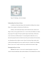
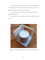
For example, Markus Kayser created a 3-D printer in London, flew it to Cairo, Egypt,
and used the sun to melt sand into a glass bowl. “Directed by a CAD design from a
connected laptop, the printer uses the concentrated beam of sunlight to slowly trace an
object into the sandbox layer by layer. The sun melts the sand, which cools into glass”
(Mone, 2011). Figure 7 shows a glass bowl made by the melting process (Quick, 2011).
14
Figure 7: Glass bowl made from heated sand
There are several clothing products. A custom, 3D-printed bikini can be made to
order (Chan, 2011). Another company uses the printer from Z Corp. for rapid shoe
design. Using the printer cuts time for design from two weeks to an overnight print, and
outsourcing previously cost $1000 per model. Now it is all done in house for the cost of
the printer and materials (“Clarks Strides into New Era,” 2011).
3D printing is gaining speed in the medical industry. You can print cells or bone
with a desktop 3D printer. Or take a scanner and scan the wound, and then print the
layers and print directly onto the patient. You can also go layer by layer and design an
organ specifically for a patient. It takes about seven hours to print a kidney. While the
technology is experimental and years from approval, it shows promise for the next
generation of medical technology (Atala, 2012).
15
While many of the 3D printed parts are made of plastic, commercial printers, such
as those made by Z Corp, are able to print a functional tool (“3D printer can print
functional tools,” n.d.).
The military has funded 3D printers. Their general goal is to speed up the
development of defense and aerospace parts (Fleming, May 9, 2012). The new NNMI
pilot institute will develop and evaluate additive manufacturing (“Public Announcement:
NNMI Pilot Institute on Additive Manufacturing,” 2012).
The startup Made in Space uses additive manufacturing to develop devices that
can be used in space. They have tested the 3D printing technology in zero gravity,
printing a small wrench (Lewis, 2011).
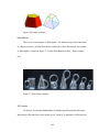
Some of the 3D printing is largely artistic. For example, Bathsheba Sculpture,
LLC created a Klein bottle opener. Figure 8 shows an example of the Klein bottle opener
(Grossman, 2012).
Figure 8: Klein bottle opener
16
George Hart was previously the Chief of Content at the Museum of Mathematics
in New York City (Hart, 2012). He is one of the leading names in mathematical
sculpture, and works as a freelance mathematical sculptor and designer. He also designs
mathematical sculpture and puzzles using the Makerbot. For example, he created a puzzle
with a single shape that fits through a triangle, circle and square. The puzzle is shown in
Figure 9 (Hart, 2012).
Figure 9: George Hart's 3D-printed visualization puzzle
17
The author created her own version of the cork problem, adding multiple cards of
one type. Hart’s design inspired additional cork problems, using different arrangements
of cards and solutions. For more discussion on this problem, see The Cork Problem as
Related to Archimedes’ Techniques on page 75.
3D Printers in the Classroom
This thesis focuses on using 3D printers for pure mathematics in the classroom.
The work of George Hart has some ideas on what can be designed and taught. The
expectation is that students are going to need 3D design skills in the workplace or at
home in coming decades. Teaching pure mathematics through use of the printers is a way
for students to gain spatial intuition, an understanding of the cost of materials, and the
general techniques for design and production of objects.
18
Chapter 2 Hobbyist 3D Printers and Printing Services
Until recently, 3D printers were either very expensive, mostly used in an
engineering company setting for rapid prototyping, or they were homemade from parts
purchased separately or as part of a kit. Either option was prohibitive to the average
person.
However, printing technology has rapidly improved, and there are many
competitors attempting to create more cost-effective versions of the printer.
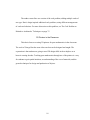
The UP! 3D Printer
For this thesis, the author purchased the UP! 3D printer. At the time of purchase,
in September 2011, the printer cost was $2425.00. The prince has since decreased and
starts at around $1499.
Figure 10 is an example of the UP! 3D printer, which was used for the project.
19
Figure 10 UP! 3D printer
In addition to the UP! 3D printer, there are other pre-assembled kits for similar costs,
including the MakerBot. You can purchase a MakerBot kit for $1749, but it requires shop
skills, such as soldering. Other kits and printers that require technical expertise can be
constructed for $500, such as the Printrbot (Drumm, 2012). This thesis assumes that not
all teachers would be interested in constructing a printer. The goal is to easily start
working with the printer for classroom models and student projects.
20
In tests with the UP! 3D printer, though the hardware and software were technically
both relatively straightforward, the documentation was inadequate. With proper
documentation, one should be able to be up and printing in well under 2 hours.
Most inexpensive and hobby-built printers use STL file output. The MakerBot
community, Thingiverse (n.d.), contains thousands of STL files. In addition, the
Shapeways (n.d.) website also has many designs, but the items there can be purchased
and printed in various materials, including colored plastics.
Setting Up the UP! 3D Printer
Installing the UP! 3D printer.
The printer was 21 pounds and arrived in about 2 days from when I ordered it.
The box came packaged with straps.
The package included everything to start printing, including:
•
The UP! Printer in Juicy Orange.
•
Power supply
•
Tweezers
•
Support material removal tools
•
Support material removal snippers
•
Platform adhesive with application brush
•
Work gloves
•
Extrusion nozzle removal tool
•
Spare fasteners
•
Basic filament spool hanger
21
•
.7kg spool of ABS-white
•
USB cable
•
UPv1.12 and QuickStart Manual available on website It also included a Testing Form that verified the inventory, whether the printer
initialized, that the platform reached 106 C, that the extruder reached 260 C and that the
filament feeder worked.
The User Manual is public, located at
http://www.up3dusa.com/support#!__support.
1. Connect extruder to printer base, which is just one screw and an Allen wrench. 2. Install the ABS spool holder. 3. Install the filament supplier. Make sure to find the longer screw in the plastic bag. 4. Install the power supply to the printer. 5. Install the power supply to the filament supplier. Make sure to plug this in, 6. Install USB. 7. Install ABS plastic reel. Feed filament into the filament supplier. This should be plugged in because if you press it down, it will feed through automatically. 8. Install platform. Not sure how to raise it. a. OK to raise it, install the software and connect with USB. b. Click 3DPrint > Maintenance. c. In the To box, set the value to 120 and then click the To button. The printer platform raises. 22
d. Note that software install instructions are for PC only. 9. Assemble platform. The screws are the longish ones in the bag, That completes the quickstart. There is an extra power supply and random other things still in the kit. There was no prompt to install drivers, as this was not part of working with the
Mac version of the software.
There were eventually several problems with the Quickstart guide. First, it did not
clearly state how to raise the platform. The application actually comes with a full help
system that explains that you should raise the platform using the Maintenance option. It
prompts you to test the platform raise.
Previously, I had attempted to print using the value listed in a screenshot. As it
turns out, this value was too high. The nozzle scratched the surface and the plastic that
came out bunched up and later clogged the nozzle.
In addition, the Quickstart guide did not clearly state how to prepare the printing
platform. One needs to paint it with nonstick paint or put down blue tape onto the
platform. After the author figured this out and also set the nozzle height correctly, the
printer mostly worked.
However, the Mac version of the software is not as fully tested as the PC version.
For example, it is missing the stop print button. With the Mac version, you need to wait
until all the printing has ended. I attempted to print the five platonic solids. It appeared to
only create a base for one, which started to print nicely but ended up degenerating into a
blurry nest of plastic.
23
The software failed to install on Vista, so my PC was not useful here. Eventually I
upgraded my machine to Windows 7 and it worked.
I spent some time installing VirtualBox on my machine with a Windows 7
license. This was fairly tedious, but the software correctly attached to the printer. I
attempted to print the platonic solids a second time, and this time it printed three of the
five shape bases, and then created a plastic mess later on. This printout was better, but not
perfect. I cannot say whether the drawing, which I downloaded from Thingiverse, was
useful or not.
On September 24, 2011, I called up the UP! resellers, X-Object, and they gave me
some new information. The author had many problems with the printer disconnecting. As
it turns out, my version of the printer arrived with three power cords, plus an additional
cord with two female ends. There were no instructions on what to do with this additional
cord, so I left it out. He said one reason that I might be having issues is that I am using
three power cords, instead of the one cord and the two-female cord. He claims that this
should fix my problem and make the printer more stable.
In addition, I had been having some issues with the actual printouts. In the
manual, there is a whole section on calibrating the printer. You can download files and
print them out, and the instructions walk you through calibrating the printer for better use.
I have been having issues with the printer creating tangled nests of plastic, and when I
print a sphere, it is conical on the bottom and sphere-like on top. After several tries, I was
able to get the calibration models working and got better, though not perfect results. In
particular, the spheres had perfect tops, but the bottoms were somewhat cone-shaped.
24
According to a call with the manufacturer on Friday, September 23, 2011, it takes
about a month to really get to know the printer and go up the learning curve. This might
be an issue for teachers who do not want to spend time on the learning curve, while
others might enjoy the tweaking. Eventually, the UP! 3D printer worked well enough to
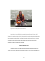
print most shapes designed in Google SketchUp, and worked very well for a demo in a
Harvard calculus class.
Other Inexpensive 3D Printers
One of the earliest hobbyist 3D printing projects is the RepRap. The general goal
of the RepRap project is to create free, self-replicating machines that anyone can use. It is
a project with its own community and wiki (“Welcome to RepRap.org,” 2012). RepRap
stands for Replicating Rapid Prototyper. Predictions in 2005 were that such a machine
would never replace mass manufacturing, but that if you consider the amount of
customization a RepRap allows, it might be a moot point (Casico, 2005).
The eMaker Huxley looks is a low-cost, high-resolution (.0125mm) 3D printer.
This was originally funded by an Indigogo project, which uses crowdsourcing, or many
individuals paying small amounts in return for some benefit, in this case a printer or parts
(Giacalone, 2005). The full printer kit costs about $627, and is based on the RepRap
project. You can buy parts from various places, on the eMaker Huxley site or other sites
like Thinkl33t (n.d.).
BotMill sells another 3D printer for $1395, based on the RepRap Mendel (“Glider
3D Printer Fully Assembled,” n.d.). They claim that this is the most inexpensive fully
assembled kit available. BotMill was recently acquired (“BotMill Acquired by 3D
Systems,” 2012).
25
The Makerbot printer is one of the most well known models, and has appeared in
numerous articles and television shows. There is competition in the space but it is
fragmented. Reviewers still say that it can be difficult to work with and that the printer
cannot be left unattended while printing (Lee, 2011). However, as of December 2010 the
company had sold 3000 printers, and were having difficulty keeping up with demand.
The printer is designed to make production cheaper and more democratic (Kiss, 2010).
Along with its “democratic” intentions, it provides assembly instructions online
(“Thing-O-Matic Assembly Instructions / User Manual,” n.d.), as well as a large
community to share its files, Thingiverse. The MakerBot Botcave store is dedicated to
selling printers and accessories with a storefront.
The MakerBot brand has also attracted $10 million in investment from the
Foundry Group. They are interested in the lower cost printers, stating that previously 3D
printers cost $10k to $500k (Primack, 2011).
The Vienna University of Technology boasts the “world’s smallest 3D printer.” It
is about the size of a carton of milk and costs about $1515. It is designed using additive
manufacturing technology, where material of 1/20th of a millimeter is hardened with a
beam of light as layers are added, which makes for much better precision for small parts,
including the tiny parts for hearing aids (Aigner, 2011).
The fab@home (2012) is a 3D printer that you can buy a prefab for $3300. It was
started at Cornell University in 2006. “The Fab@Home Project is an open-source masscollaboration developing personal fabrication technology aimed at bringing personal
fabrication to your home.”
26
There are two places for significant improvement in the hobbyist 3D printer
market: better results and lower cost. One blog claims to be making a low-cost, highresolution printer (Veloso, 2011). Kickstarter, a crowd-sourcing website, has had several
3D printers are also being developed. One such project wants every school to have one,
and is trying to develop a very small unit at a very good price. It appears that this printer
might go for as little as $500 (Drumm, 2012).
A new printer, the Cube 3D printer, markets itself in simplicity. It is easy to
install, uses wifi instead of a direct cable, and is easy to maintain (“Cubify,” 2012).
CNC Machines
CNC machines similarly create 3D objects, but they use a reverse method. Instead
of additive manufacturing, they often mill or cut away from an existing piece of material.
The printer takes a block of a material, for example wood or foam, and cuts away
material. These machines are similar to 3D printers in that they take a CAD drawing and
convert it into a design that the CNC machine uses to mill the new part (Ryan, 2009).
One such machine was made almost entirely of LEGOs (Goodman, 2011).
Third-Party Printing Services
If you want to work with 3D printing with students, but cannot invest in your own
printer in terms of time or finances, there are also several services that allow you to print
out parts. The costs for individual parts can be under $5, though, for example, Shapeways
does not allow you to place an order for less than $5, which can include multiple parts.
As many student classes require, a small lab fee could be included to cover the materials,
or the total funding for projects might be inexpensive compared to purchasing a printer
27
(“Shapeways,” n.d.). Shapeways recently attracted $6.2 million in funding and had its
millionth sale (Fleming, June 21, 2012).
The author worked with Shapeways at times. The service is easy to set up, and it
is fairly straightforward to load a piece and order it. In general, it was easiest to work
with pieces designed in millimeters and uploaded into Shapeways in millimeters.
Otherwise, the piece was often quite large when imported, and therefore expensive. The
Shapeways service checks the model to make sure that it is printable. However, the check
is not perfect, and one model was sent back twice to be corrected. This is frustrating,
because it often takes a couple days for the next rejection to appear. The final models that
arrive from Shapeways tend to be of much higher quality than the pieces that can be
printed using the hobbyist printers.
Sculpteo (n.d.) is another site where you can upload designs or use their tools to
design your own creations. Both Shapeways and Scupteo allow you to sell your parts
online.
Another 3D printing service is i.materialize (n.d.). They use several materials and
several types of additive manufacturing, depending on the material. For example, they
have a one-minute discussion about how laser sintering works. A layer of powder is put
on a platform that is heated, then a laser hardens the powder, then another layer of
powder is added and lasered, until it becomes a final shape. Stereolithography is a similar
process, using a liquid polymer instead of powder, as well as supporting material.
Another method (for ABS plastic) is Fused Deposition Modeling, which is the standard
hobby printer method of forcing melted material through a nozzle in layers. It also
includes a support later that is removed in a bath with soap. They also have a chart of
28
supported materials. For example, with gold the design is printed in wax and then molten
gold is poured into the mold (“i.materialize,” n.d) ).
Also on the i.materialize website is an article about how a Rodin Thinker was
burglarized for scrap metal and partially destroyed. Using 3D printer technology, they
were able to help put it back together by creating a mold for restorers (Peels, 2011).
Autodesk, manufacturer of the AutoCAD software, now has its own service that
allows you to export to STL and even create a printout for you (“Make your models real
with 3D printing,” 2012) .
Printers in Your Neighborhood
Many colleges, including Harvard University, own commercial-grade printers that
can be signed out by their students. Harvard allows students to order their own printouts
using printers from Z Corporation, Stratasys, and Objet. Like printer services, this allows
students to pay by the part (“Fabrication Lab,” n.d).
Neighborhoods businesses are starting to invest in the technology. In Somerville,
MA, the Artisan’s Asylum acquired a 3D printer in February 2012, and offers
introductory classes on the printer. Anyone can pay a daily or monthly fee to have access
to the printer for their own use (“Artisan’s Asylum,” n.d.).
The author attended the 3D printer tool training at Artisan’s Asylum on May 26,
2012. The course was taught by Gui Cavalcanti, President of the Asylum. They have a ZCorp uPrint SD Plus printer valued at $20,000. The print area is about 8 inches by 8
inches by 6 inches. To use the printer, members must pay a daily, weekly, or monthly fee
for use of the space, plus $9.50 per square inch of material.
29
The uPrint can print STL files that have been loaded into the ZCorp Catalyst
program. The program attempts to print any STL, whether it is designed correctly or not,
meaning that one could attempt to print and find that one’s result was not what was
expected. In terms of good design, parts shrink after printing. The exterior shrinks 99.7%
and the interior 98.5%. Because of this, one must design your parts to take shrinkage into
account. There are several other design rules for printing.
Unlike commercial printers, this printer has two outputs, the main material and
the supporting material. The supporting material can be removed by soaking the printed
part in a lye bath (Cavalcanti, 2012).
The output of this printer is of a significantly higher quality than the standard
hobbyist printers. The supporting material allows you to print pieces with space and
overhangs and not worry about the part printing crookedly or otherwise failing. However,
there are many steps and rules for working with the printer, as well as significant costs
for materials and use of the facility. This makes it impractical for those without time and
money, or at least a good design background. The experience of working with a quality
printer could be worth it, especially for designs that require precision.
Commercial Printers
As mentioned in the previous section, ZCorp offers some of the least-expensive,
commercial-grade printers. An article about making custom bone implants discusses how
the ZCorp printer works, “Ink-jet printing is a layer manufacturing technology that
fabricates three dimensional models from CAD data. The process consists of forming
layers (0.1 mm thick) by using a printer-like device to distribute an adhesive to bond the
surface of a powder into the desired shape …Liquid binder is ejected from the ink-jet
30
printer (Z406 3D color printer: Z-corporation, Burlington, MA, USA), and with the
repetition of the hardening of the powder material on the flat surface (hydration), a solid
figure is formed.” (Igawa et al., 2006)
However, Z Corp also offers high-end printers, such as the Z 810 for $180,000.
This printer can develop larger objects. The company Objet Geometries sells a $115,000
3D printer to make patters for silicone tooling and prototypes (Sherman, 2004).
Stratasys, who builds the Dimension printer, announced a high-end printer, the
Mojo 3D Printer, for under $10k, the “lowest-priced, professional-grade complete 3D
printing system” (Fleming, May 8, 2012).
In general, stereolithography machines can cost up to $500,000, selective laser
sintering machines cost up to $325,000, and fused deposition modeling machines cost up
to $300,000 (Sherman, 2004).
31
Chapter 3 3D Graphics and Design Tools
One can use any software that can import and export STLs to design and
manipulate STL drawings. Software can be free or might cost hundreds for a license. This
thesis particularly focuses on the free Google SketchUp software, as it is easy to obtain
and learn the basics. The thesis also considers using Mathematica (Wolfram Research,
2010), which can create more exact models while exploring the mathematics behind
objects.
Learning to think and design in any 3D drawing program takes patience and
practice. Even though the author has taken courses in MiniCAD, AutoCAD, and
Pro/Engineer, learning new packages was still slow, and learning how to create objects
acceptable to 3D printers is ongoing.
Google SketchUp
Google SketchUp (Google, 2010) is one of the easiest tools to obtain and start
working with for 3D design. One of the first printed books for working on 3D printing in
a hobbyist fashion is the Beginning Google SketchUp for 3D Printing by Sandeep Singh
(2010). This book focuses on how to create 3D models in Google SketchUp, and then
create a Shapeways account and sell pieces for a profit. It goes through how to install
Google SketchUp for 3D printing, as the program does come with STL importing and
exporting. Ones needs to configure this oneself.
32
It talks about how to create basic pieces in SketchUp, how to use photographs as
models, and how to share 3D objects. It is careful to describe the limitations of what
Shapeways accepts, for example, all walls must have a certain minimum thickness, and
you must be careful to close models correctly or they will not be accepted. This was
probably the most useful part of the book, as the author of this thesis struggled at times to
create pieces that were printable.
In Braga’s (2011) Google SketchUp tutorial for 3D printing, he states that out of
all free tools, SketchUp is “the easiest to acquire and learn”. Because SketchUp takes
limited file types, it also includes a method to import AutoCAD files.
AECbytes is a blog by a writer, Bonnie Roskes, who uses SketchUp to teach
students. She blogs regularly on how to use different tools in SketchUp and has written
books for children who want to use SketchUp. For example, in her book Kids as
Architects (For the PC): Buildings Kids Wish Would Really be Built, Modeled in Google
SketchUp (2008), she walks through how to create buildings, teaching SketchUp tricks
along the way. For example, one building is based on a rainbow design, with each arch of
the rainbow creating a deeper level to the building. It is fairly simple, but uses some
sophisticated tricks (Roskes 2008). In a blog post in AEC Bytes, she discusses how to
create windows in an object using the intersect tool (Roskes, September 25, 2008). Her
blog focus is on 3D design, and in June 2012, she notes that she is interested in MakerBot
printers (Roskes, 2012). Roskes also produces a SketchUp Geometry Project of the
Month (Roskes et al., 2012). They have student and teacher versions.
33
Mathematica
Mathematica allows you to create 3D drawings and export them directly to STL
format. You can view the graphics in Mathematica using the Graphics3d function
(“Graphics3D,” 2012). You then export the 3D objects using Export[“file.stl”, expr]. You
can also import STL files (“STL, .stl”, 2012). Mathematica by default exports STL files
in binary format instead of ascii format, so you might need to convert the files to work
with your 3D printing program.
To get an idea of how the Mathematica export might print, one can test by
importing the STL file into Mathematica. When one views the file, it is possible to see if
it exported as expected. At times, the STL format might not export in an expected way,
and might require changes.
Mathematica has several built-in shapes that can be printed, for example, the
cuboid or sphere. One can print parametric plots or other shapes as well. However, it is
important to be careful that all walls have thickness to them in order to be accepted by a
3D printer.
Blender
Blender is a free, open-source tool for building 3D graphics, typically used for 3D
applications and video games. It is available under the GNU General Public License
(Kenney, n.d.). However, Blender is also increasingly popular as a modeling tool for 3D
printouts.
34
Blender was tested for the thesis, but it is fairly complicated to learn the various
required mouse movements and shortcuts for the basics. Google SketchUp was more
immediate.
OpenSCAD
Look into OpenSCAD, which appears to allow one to put in parameters and have
the program render them. It is possible to use this software to extrude 2D objects into 3D
(like using the Google SketchUp Push/Pull tool) or to combine existing 3D objects using
a technique called constructive solid geometry (CSG) (“OpenSCAD – The Programmers
Solid 3D CAD Modeller,” 2012). CSG allows one to create objects using solids created
out of convex objects created with coplanar intersecting faces (“What is Constructive
Solid Geometry,” 2006).
OpenSCAD is not as useful for artistic 3D drawing and is more for functional
pieces. It is suited to 3D printing, however, it might be too complicated for younger
students.
AdMesh
AdMesh processes triangulated solid meshes, such as STL. It allows one to
change an STL file to ASCII, or to rotate, resize, and repair STL files (“AdMesh version
0.95,” 2012).
For example, the command “admesh – scale 0.2 –b out.stl in.stl” scales the
original STL file by .2 and exports to binary. Use the -a for ascii. Shapeways accepts both
but ascii has larger file sizes. The UP! 3D Printer and Google SketchUp only accept ascii.
35
MeshLab
MeshLab is an open source tool with a UI. It is designed to work with files in
several 3D formats, particularly those that come from 3D scanners. It provides several
tools to edit and clean up 3D files (MeshLab, n.d.).
In testing, this was a useful tool to convert binary STL files produced by
Mathematica into ASCII files used by 3D printing software or Google SketchUp.
Other Tools
If available, students can work in ProEngineer, AutoCAD, Solidworks, or any
other powerful 3D graphics tool. All of these can cost a lot of money and might not be
available in an average high school.
MakerBot includes tutorials for open source programs including:
•
Blender •
HeksCAD •
OpenSCAD •
SketchUp •
3D Model Archives •
G-‐Code •
Electronics •
Skeinforge (Tutorials, n.d.) 36
IPad and IPhone Applications
There are now some applications with limited functionality that you manipulate
3D images. The Beautiful Modeler application lets one do multi-touch design on an iPad
for 3D modeling. However, the instructions to make it work are complicated.
MeshLab has a simple iPhone program that allows one to view your 3D models
(“Meshlab for iOS,” 2011).
AutoDesk is well known for its AutoCAD product, which has been used for
decades for engineering design. You can use these products to design in 3D and export to
STL for printing. The company’s products are unfortunately expensive and not feasible
for a standard high school.
However, they are also moving into the consumer markets with some of their new
products targeted at non-engineers. For example, the 123D Catch tool is free. It allows
you to take a series of photos and convert them into a 3D design, which can be printed.
This technology could make a 3D scanner obsolete (“123D Catch,” 2012). The 123D tool
allows you to design, and is available on the iPad, so you do not need a computer to work
on your designs.
The computer software iScan3D is an iPhone app designed to work like a 3D
scanner. It allows a user to take 5 to 30 pictures of an object and combine them into a
shape that can be exported as an STL file, which can then be printed (“iScan3D,” 2012).
3D Printer Software
Most 3D printers use their own software to take a file in STL format and slice it
into wafers or other usable format for printing. The STL file was developed by the Alber
37
Consulting Group in 1987 to take 3D CAD models for use by 3D Systems for their
stereolithography machines. The format takes a surface and breaks it into triangular faces,
and is inherently limited by not working accurately with smooth curves. STL can be
created in binary or ASCII format, though not all printers take both. Eventually an
improved version of STL might be necessary (“STL 2.0 May Replace,” 2009).
3D Scanners
Three-dimensional scanners are used to take images of existing objects to be
converted to a file in a useful format, such as STL. There are many technologies for 3D
imaging, such as the CAT scan, or by taking visual images circling the object. Like the
STL, some types of range scanners are a triangulation system where a pattern of light is
projected onto the object to be scanned (Bernadini, 2002). The scanners take thousands or
even millions of measurements of an object’s geometry in order to translate it into a
usable format.
One might need different scanners depending on whether the object is close range
or far, or if you need a great deal of detail versus just the general outline. For example,
laser triangulation scanning works by shining a laser on an object and calculating the
distance using the light that is reflected. This allows for good close-range scanning, but
with poor accuracy. Lasers shine differently on different types of material. Alternately,
structured light 3D scanners shine light patterns on an object and calculate where the
edges are located (“3D Scanners: A guide to 3D scanner technology,” 2012).
38
Chapter 4 Projects for the 3D printer
A 3D printout originates from an idea that was designed on a screen. In general,
the image can be rotated and viewed at any angle, so why is it useful to have the printout?
The difficulty is that a 3D image on a screen is still two-dimensional. Some
problems are still difficult to understand even when you can see the image. These
problems might benefit from a student being able to use their depth perception to
understand a problem. In other problems, a student might be able to take two or more
printed parts and combine them or compare them. In addition, 3D printing opens up
mathematical discussions to those who might not have depth perception or might be
blind, by providing a tactile object to study rather than to have it described by a book or
another person.
Another aspect of the 3D printing exercise is trial and error. You might design an
object and print it out, only to find that it does not work for your purpose. Another
interesting example is that you can design objects in Mathematica that you print directly
to an STL file. As a test, does the design actually print? Is the printout like the intended
design?
The parallelepiped problem is one example of a problem that is difficult to see
even when you have the image right in front of you. Take six tetrahedrons and combine
them to create a prism. The solution to the problem is not obvious, and a two-dimensional
rendering of the three-dimensional object has so many lines that the solution is
39
obfuscated even when it’s right in front of you. By printing out the individual
tetrahedrons, you can combine them all, perhaps with a gentle adhesive. As you can color
or otherwise mark each piece to keep track of which piece went where. If you want to see
how a few pieces combine after you construct the prism, you can take the prism apart and
see where it cleaves and what other structures might be created as part of the
combinations.
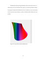
Another application is printing rotations in multivariate calculus. One classroom
project created a very simple 3D apparatus to print out a rotation that was designed in
Mathematica. By its nature, a 3D printer works like a calculus problem. Because it cannot
print a whole solid all at once, it must print in stepped layers. It is a sort of calculus in
action, which might be a good discussion point for introductory calculus classes.
Another possible lesson is as a demonstration for some of the concepts introduced
in the novel Flatland (Abbott, 1992/1884). In the novel, a 3D figure attempts to
communicate to a 2D figure what a 3D figure looks like. Again, this is a good
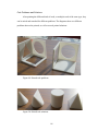
introduction to change and calculus that can be introduced to children at an early age.
One demonstration is the pyramid. From one angle, a two-dimensional cut looks like a
square, anywhere from the base to the top point. Another face is a triangle, and the corner
is also a triangle. The triangle changes depending on the actual angle you cut. Pieced
together from a 2D world, you can almost envision the 3D object.
Objects are fairly inexpensive to print, and they are easy to draw on. For example,
you could print out a dozen spheres and talk about the surface area, volume,
circumference, and so on.
40
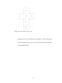
Another interesting lesson is to print out the Platonic solids. Many teachers ask
students to map out the number of vertices, faces, and edges of each solid. This is, again,
difficult to keep track of, particularly for the dodecahedron and icosahedron, but by
having an inexpensive shape to draw on and label, it becomes much easier. One early
video game that is often a project in computer science classes is Hunt the Wumpus,
where a series of caves is connected on a dodecahedron structure. You cannot design this
game without fully understanding the dodecahedron.
Figure 11 Printed double dodecahedron
Printers are already in high schools and even younger grades. The general
applications for these are design courses, usually to encourage students to careers in
41
engineering. For example, students at Chico High School worked with Kleen Kanteen
and Dimension Printing to design new parts for the Kanteens (“High School Students Use
3D Printing,” 2012).
There are many advantages to teaching with 3D Printers, including designing
enhanced teaching aids offline. For example, if a teacher talks about the Taj Mahal, along
with the words and pictures found in a book, you can create a miniature model to study.
Students can create projects in architecture and engineering, or other 3D projects. And
3D printers can be interactive, for example, by creating a 3D model of a student’s head
for biology class (“Three Advantages of 3D Printing in Schools,” 2012).
This chapter includes several basic plans for creating shapes useful to a basic
geometry course. The following chapters cover more advanced topics in mathematics. .
This set of lessons are possibilities for teaching students to think in basic 3D
shapes and beyond. The lessons are largely how to set up and use Google SketchUp,
though the basics of Mathematica are also included.
Working with Google SketchUp
Change the template in Google SketchUp
The UP! 3D printer has a limited print area of 140 by 140 by 135mm. Because of
this limitation, it is easiest to design using a millimeter template. The default Google
SketchUp template is in meters. In addition, walls must be at least 1 mm thick for objects
to print correctly.
To change the template:
1. Click on SketchUp > Preferences. 42
2. In the menu, select Template. 3. Select the template Architectural Design – Millimeters. 4. Close the window. Note: There is no save button. In order to use the template, you must open a new drawing. (“What are templates,”
2012)
Designing and Printing Simple Shapes in Google Sketchup
Prerequisites:
•
PC with Google Sketchup installed, available at http://sketchup.google.com/.
•
Google Sketchup plugin to import and export STL files.
•
A 3D printer or arrangement to work with a company such as Shapeways.
To install a plugin to import or export STL files:
1. Obtain a plugin that imports and exports STL content. (One website is
http://www.cerebralmeltdown.com/cncstuff/stl/index.htm).
2. Copy the plugin file to the Google Sketchup folder. On a Mac, this is
Macintosh HD\Library\Application Support\Google SketchUp
8\Sketchup\plugins.
3. Start Google Sketchup. You should see a new menu for Plugins, if you
haven’t see it previously. The menu has options to import and export STL
files.
To learn try working with some of the basics in Sketchup:
43
1. Open Google Sketchup. The standard first screen is a coordinate system
with a character standing by the origin.
2. Click on the character to select it. A selected character is enclosed by a
blue box.
3. Type “Delete” to remove the character.
4. Click the “Rectangle Tool.”
5. Click anywhere in the coordinate system. Notice that you can draw a line
along the x-axis or the y-axis. Then drag out to a square. You can also
click and drag diagonally between any two axes to get a square or
rectangle immediately.
6. Click the “Push/Pull Tool.”
7. Click one of the rectangles you just created, and move the cursor along the
z-axis to create a box,
8. Select an yz face and use the Push/Pull Tool to change that face of the
box.
Volume of a cube
1. Open a new file. 2. Select the rectangle tool. 3. Click on the origin. 4. Type “100,100” and then type “Enter.” You should see a square drawn along the x and y axes. 44
Figure 12: Drawing a square in Google SketchUp
5. Click the Push/Pull tool. 6. Pull the square up. In the Distance box, type, 100. Figure 13: Using the Push/Pull tool to finish a cube in Google SketchUp
You now have a 100 by 100 by 100 millimeter cube.
45
Export the cube
1. In Sketchup, click Plugins > Export STL file. An error appears, “No selection. Export whole model?”
2. Click Yes. The ExportSTL popup prompts you for units to export. 3. Select “Centimeters,” and then click “OK.” 4. In the “Select file to export to” pop-‐up, name the file, select a location, and then click “Save.” The file is exported as an STL.
Opening the cube in the UP! printer software
1. Open the UP! software. 2. Click File > Open. 3. You might have to set encoding or change the model size. Discussion
If you were to double the base and height of the cube, what would the new size
be? How many of these cubes would you need?
Designing and Printing Simple Shapes in Mathematica
Unlike Google Sketchup, Mathematica software has STL output as part of its outof-box functionality.
1. Open Mathematica. 2. Use the Graphics3d function to create a cuboid. There are several built-‐in 3D shapes available. For the cuboid, type: 3. Graphics3D[{Blue, Cuboid[{1, 1, 1}, {2, 2, .5}]}] 46
4. Evaluate the cell to see what the image looks like on screen. Figure 14: Creating a Blue Cuboid in Mathematica
To export the cuboid as an STL,
5. Export[“cuboid.stl”,Graphics3D[{Blue, Cuboid[{1, 1, 1}, {2, 2, .5}]}]] 6. You can then open the graphic in the UP! printer software. 47
Design a Pyramid in Google SketchUp
1. Open a new file. 2. Select the rectangle tool. 3. Click on the origin. 4. Type “200,200”, and then type “Enter”. You should see a square drawn along the x and y axes. 5. Click the Line tool. 6. Click a corner of the square, and then draw a diagonal to the opposite corner. 7. Draw another diagonal using the other two corners. Figure 15: Drawing diagonals on a square
8. Select the center of the square and draw a vertical line along the blue axis. 9. Type 200. This sets up a pyramid with sides 200 and height 200 48
Figure 16: Setting the height of the pyramid
10. Connect a corner of the square to the top endpoint of the height line. This creates a filled in triangle. Consider the area of the triangle. Figure 17: Creating a triangle in the pyramid
49
11. On a corner next to the one you’ve drawn the triangle, draw another line from the corner to the endpoint of the height line. This creates an irregular tetrahedron. Figure 18: Drawing an irregular tetrahedron
12. Connect the other two corners of the square to the endpoint of the height to complete the pyramid. 50
Figure 19: A completed regular pyramid
Design a Cylinder in Google SketchUp
1. Open Google Sketchup.
2. Click File > New.
3. Click the Circle tool.
4. Click the origin and type 500, then Enter. A circle with radius 1000 appears.
5. Click the Push/Pull Tool.
6. Click the circle and type 1000. The cylinder that appears has diameter 1000
and height 1000.
51
Figure 20: Completed cylinder
Draw a Cone in Google SketchUp
Ensure that you are using the Architectural Design – Millimeters template.
1. Click File > New. 2. Click the Circle Tool. 3. At the origin, draw a circle with radius 50 mm. Note that even though you are using the millimeter template, the circle appears to be very small. 4. Using the Zoom tool, zoom into the circle. You might need to use the Pan tool to keep the circle approximately in the center. 5. Click the Line tool. 6. Draw a line starting at the origin and along the z-‐axis to be 50 mm long. 52
7. Draw another line from the top endpoint of the line to the edge of the circle, and then another from the edge of the circle to the center of the circle. When drawn correctly, a triangle appears with a white filling. Figure 21: Create a cone using a circle and triangle
8. Click the Select Tool. 9. Click on the circle. 10. Click Tools > Follow Me. 11. Click on the triangle. The triangle “follows” the circle and creates the cone shape.
53
Figure 22: Completed cone
Discussion:
•
What is the relationship between the cone and the cylinder? •
How do you compare the relationship with the cone and the cylinder with the relationship between a regular pyramid and the cube? •
What is interesting about the cone in terms of calculus? Odd-Shaped Base
In this section, combine squares, triangles, and circles into any base. For example,
I drew the following shape:
•
A square with sides 1000. •
A circle centered at the square corner with radius 500. 54
•
A triangle starting at the corner of the square with height 500 and base 1000, that of the square. Combine the three shapes to get the following base.
Figure 23: Odd-shaped base
How do you calculate the base?
Square = 1000×1000
!
¾ of Circle = 𝜋500! × !
!
Triangle = 500×1000× !
Now that we have the base, let’s add some dimension to it, and use the Push/Pull tool to create an object with height 1000. As this is base × height, multiply the base by 1000. 55
Figure 24: Odd-shaped solid. Reverse Volume and Surface Area Exercises
After you create one of these basic models, you can do things with them, for
example:
•
Measure the volume versus weighing the object. •
Cover the object in paper and “cut out” the form to recreate it, thereby learning about the surface area. For example, an image of the flattened cube looks like Figure 25 (“Cube template,” n.d.). 56
Figure 25: Cube surface area cut out
•
What sort of cut out would create a cylinder? A cone? A pyramid? •
Can you create an accurate cut out to fold a sphere? Discuss world maps and distortion. 57
Chapter 5 Exploring Archimedes
Archimedean mathematics started where Euclid left off, and he was able to create
basic methods for integration for several shapes that could not be measured by Euclid’s
methods alone. These include, for example, finding the volume and surface area of a
sphere, by analyzing the volumes of more straightforward shapes such as the cylinder and
cone. His method of figuring out this early form of calculus is somewhat mysterious,
though it might have been influenced by his work on mechanics. His proofs often rely on
comparing shapes and ratios, and are very interesting to think about in relation to their 3dimensional printouts (Heath, 1981/1897).
Oliver Knill and the author, Elizabeth Slavkovsky, are working on a paper “On
the Trails of Archimedes with a 3D Printer,” (work in progress) to be completed in honor
of Archimedes’ birthday in 2013.
Estimating the Area of a Circle
Theorem: The area of a circle lies between the area of an internal regular polygon
and an external regular polygon, each with the same number of sides and all vertices
touching the edge of the circle.
Archimedes explored the relationships between several different shapes to come
to his conclusions about the relationship between a sphere and a cylinder. To get there, he
first learned about the circle, attempting to determine some of the ratios around the circle
when you draw a polygon on the inside and outside of the circle. He then continues the
58
idea of the ratios to include the relationship between the circle, the pyramid, the
tetrahedron, and the cone. Eventually he connects all of these ideas to the sphere and the
cylinder.
He used Euclid’s methods to outline his work “On the Sphere and the Cylinder.”
He first outlines definitions and assumptions, and then builds his case through a series of
propositions.
The area of a circle is
𝐴𝑟𝑒𝑎 = 𝜋𝑟 ! However, if we do not know that about a circle, we could estimate the area inside
the circle but inscribing a polygon where each corner touches the circle and dividing it
into triangles. For example, if you divide into six equilateral triangles, we can divide a
unit circle into 12 of the 30-60-90 triangles, with the total area:
𝐴𝑟𝑒𝑎 = 12×.5×.8660 Similarly you can compute the area of the 12 circles by drawing a hexagon
outside the circle, with each edge tangent to the circle. Create a similar area. If you find
the mean of the inside and outside areas, you’ll have a better estimate of the circle’s area.
You can print a ”circle” that includes the inner and outer polygons, as well as an
inner triangle division. To create the base circle:
1. Open Google Sketchup. 2. Click File > New. 3. Click the Circle Tool. 4. Starting at the origin, draw a circle with any radius. 5. Click the Push/Pull tool. 59
6. Pull the circle up a small amount so that it looks like a cookie. To divide the circle into triangles for estimation, you continue to work in the same
drawing:
1. Click the Polygon Tool. By default, the Polygon Tool creates a hexagon, which is what we want. 2. Create a hexagon starting from the center of the circle with vertices touching the circumference of the circle. 3. Click the Line tool. 4. With the Line tool, draw six lines from the center to each vertex. 5. Select the three lines that outline one of the resulting triangle. 6. Select Tools > Offset. 7. Click inside the selected triangle to create a new triangle just a bit smaller than the original. 8. Copy this triangle and paste it to the two similarly oriented triangles in the circle. Then flip the triangle and paste it to the other three triangles. 9. Click the Push/Pull tool. 10. Push each of the six triangles to the bottom of the original cookie, so that they have no depth. 11. Push the remaining triangular ”frames” down to the about half the height of the cookie. The frames will be inset in the original cookie. This illustrates the basic breakup of a circle.
60
Figure 26: Breaking a circle into triangles
Understanding Area Versus Volume
A random two-dimensional shape can be estimated by dividing it into common
shapes, where triangles are often the most flexible choice.
Similarly, a three-dimensional shape can be divided into some common set of
shapes, in this case, the pyramid. In this case, we can also show the difference in volume
using weight. The weight in 3D objects printed using the same density will show the
correct ratios between different objects. It is interesting that Archimedes was very
interested in proportions and uses them heavily in his proofs, and some of his inventions
were dependent on their weights or center of mass. He ends up slicing a sphere and a
cylinder and showing that the areas are equal for each slice. In another way of thinking
about it, if you were to ”weigh” each slice, they would also have the same weight.
Estimating the Size of a Cone
Theorem: The volume of a cone can be estimated using the average of the
volume of internal tetrahedrons and external tetrahedrons. The tetrahedrons have as their
61
base triangles created by a regular polygons, as in estimating the circle, with the center of
the tetrahedron as the height of each polygon.
In this section, we create a single tetrahedron with the base of one of the triangles
created in the circular cookie above. The base is a triangle created by the center and two
vertices of the
1. Open the circle drawing from before. 2. Click the Line tool. 3. From the center vertex of one of the inset triangles, draw a perpendicular line up the z-‐axis. 4. From the top point of that line, draw two more lines to the other vertices of the original triangle. You now have a tetrahedron. If you were to print out six of these tetrahedrons, you would create a rough estimate of
the volume of a cone. These tetrahedrons are designed to fit into the circle you created
when estimating the area of the circle.
Figure 27: Tetrahedron
62
The Volume of the Tetrahedron and Pyramid
Theorem: A cube can be created using six tetrahedrons or three pyramids.
The volumes of the tetrahedron and pyramid were known in Archimedes’ time.
As part of building relationships between the shapes and numbers, Archimedes used the
idea that a pyramid’s volume is one-third the volume of a cube to work with Euclid’s.
Beery (2009) points out that Archimedes understood the sum of squares for the first n
positive integers, or:
𝑛 + 1 𝑛! + 1 + 2 + 3 + ⋯ + 𝑛 = 3(1! + 2! + 3! + ⋯ + 𝑛! )
so for n=4:
3 1! + 2! + 3! + 4! = 5 ∙ 4! + (1 + 2 + 3 + 4)
However, this is much more easily shown using irregular pyramids, as in this
image by Beery (2009):
Figure 28: Archimedes understood the relationship between the Pythagorean
formula, triangular numbers, and the volume of a pyramid and cube
63
In Google SketchUp, it is interesting to show geometry students a simple irregular
pyramid, and to construct a cube out of it.
Figure 29:Irregular pyramid in Slavkovsky's Shapeways account
The author designed an irregular pyramid and uploaded it to Shapeways. This
pyramid can be printed in multiple colors, and three such pyramids can be combined to
create a square. Shapeways can print multiple colors for some materials, which can be
used to show contrast in this example.
64
Figure 30: Three irregular pyramids
Figure 31: The three contrasting pyramids create a cube
65
In addition, you could divide each pyramid in half into two tetrahedrons, showing
that six tetrahedrons combined also create a square, as in the images below.
Figure 32: Designs for the tetrahedron
Design Archimedes’ Tombstone in Google SketchUp
Theorem: The volume of a half sphere is 2π/3. It is equal to the complement of
the volume of a cone in a cylinder, where the great circle of the sphere and cylinder are
the same.
Archimedes proved that if you have a sphere with radius r inside a cylinder with
radius r and height 2r:
66
•
“The surface of a sphere is four times that of a great circle of the sphere, •
That the surface of any segment of a sphere is equal to a circle the radius of which is equal to the straight line drawn from the vertex of the segment to a point on the circumference of the base, •
That the volume of a cylinder circumscribing a sphere and with height equal to the diameters of the sphere is 3/2 of the volume of the sphere, •
That the surface of the circumscribing cylinder including its bases is also 3/2 of the surface of the sphere” (Heath, 1981/1921) “After Archimedes was killed by a Roman soldier during the Roman conquest of
Syracuse, the Romans built an elaborate tomb on which they inscribed this theorem.”
(Kline, 1967)
To create the sphere and cylinder combination, we need to consider a few issues.
A printout of the shape requires some width to each surface, so we’ll have to include
additional width for the side and top of the cylinder, and for the surface of the sphere. In
this case, I am going to design a cylinder with the inside edge of the cylinder and outside
edge of the sphere used for the Archimedes calculation. Start by drawing the shape
without any depth to the surfaces.
Drawing a cylinder
1. Open Google Sketchup.
2. Click File > New.
3. Click the Circle tool.
4. Click the origin and type 1, then Enter. A circle with radius 1 appears.
67
5. Click the Push/Pull Tool.
6. Click the circle and type 2. The cylinder that appears has diameter 2 and
height 2.
Drawing a Sphere
1. On the same canvas, click the Circle tool again.
2. Hover the cursor on the z-axis above the cylinder until a small vertical
circle appears.
3. Click on the z-axis, type 1, then Enter.
4. If the circle intersects with the cylinder, click the Move Tool.
5. Move the circle along the positive z-axis so that it clears the cylinder.
68
Figure 33: Circle above the cylinder
6. Click the Follow Me Tool.
7. Click the top face of the cylinder to select it.
8. Click Tools > Follow Me (“How do I draw a sphere?,” 2012).
9. Click the vertical circle you just drew. The Follow Me tool rotates the
circle using the top of the cylinder as a guide, and creates a sphere. You
now have Archimedes cylinder and sphere.
69
Figure 34: Sphere above cylinder
Add Depth to the Shapes
At this point, it might be useful change your view of the shape so that you can see
through it. To do this, click View > Face Style > X-ray.
To add depth to the side of the cylinder,
1. Select the Rectangle Tool.
70
2. Starting where the circle intersects the x-axis, draw a rectangle with width
.08 and height 2.
Figure 35 Cylinder
3. Click the top circle to select it.
4. Click Tools > Follow Me.
5. Click the rectangle you just created. The rectangle rotates around the side
of the cylinder, creating depth.
71
Finishing the Model
At this point, you have all the pieces for a printable object. In order to see the
whole printout, the easiest method is to remove the top and bottom of the cylinder:
1. Move the sphere into the cylinder, so that the bottom of the sphere aligns
with the origin.
2. Export the STL using Plugins > Export STL file. When prompted, agree to
export the whole model.
Figure 36 Completed sphere within cylinder in UP! 3D printing software
72
This also needs a cone shape, and you can design the cylinder, cone, and sphere
separately, or create pieces. The half sphere has height z and radius 1. One can show that
the cone within the cylinder has the volume 1/3 x Pi. Therefore, the cylinder minus the
cone is (2/3) x Pi. It is possible to then show that this area is equal to the sphere’s area,
and therefore the sphere’s area is 2/3 of the cylinder’s area.
The Archimedes Tombstone Hands-On Demo
Another take on the Archimedes problem is to show the similarity in volume
using water. In this case, you create a half-sphere with an internal volume equal to the
complement of the cone created by the same radius and height of the half-sphere.
What Archimedes showed was a precursor to calculus. If you take a unit halfsphere, imagine cutting the sphere into a series of disks. Each disk is at height z from the
center of the sphere. The distance from the center of the sphere to the edge of the sphere
is always 1, as this is the unit circle. Therefore, the radius of any given disk is:
π√(1-z2)
The area of the disk is:
π(1-z2).
For the complement of the cone, also created by the unit circle, again picture a
series of disks, each with a hole in the middle like a donut. In this case, the radius of the
cone at height z is also equal to z. So, the radius of the complement is π – πz2, or π(1-z2).
This is the same value as for the half-sphere.
The volume of the cylinder is π and the volume of the cone is (π/3). Therefore the
volume of the complement of the cone is (2/3)xPi. As the area of a sphere at a given
73
height z is the same for both the half-sphere and for the complement of the cone, the area
of the half sphere is the same (2/3)xPi.
In this example, created in Mathematica but easily replicated in Google
SketchUp, the top portion is the unit half-sphere. The bottom portion of the printout is the
complement of the cone. There is a small hole in the half-sphere. If you cover the hole
and fill the half-sphere with liquid, and then open the hole, the liquid pours into the
bottom half, filling it exactly.
This design is currently uploaded to the Shapeways site, and can be purchased by
anyone for demonstrations. The Mathematica code is given in Appendix 2 . Note that
Mathematica is set to export the design to STL. One of the more complicated problems
with designing in Mathematica is giving the printout some depth. The final printout of the
funnel was printed using the Shapeways service, as this type of geometry could not be
managed on the UP! 3D printer.
74
Figure 37: Archimedes Tombstone funnel demonstration
The Cork Problem as Related to Archimedes’ Techniques
Martin Gardner (1961, p. 52-54) explained the “cork plug problem” in The
Second Scientific American Book of Mathematical Puzzles and Diversions. The cork
problem is illustrated in George Hart’s 3D printing gallery, as shown in Figure 9: George
Hart's 3D-printed visualization puzzle.
One can use any three shapes, or even repeat shapes, with students and have them
design their own puzzles. It might, for example, be interesting to show that the puzzle
with three circles, a solution to the puzzle is a sphere. For three squares, one solution is a
cube.
75
One possibility is to have a base to put in the printed “hole cards”, and have
students design a shape to fit into them. Print out their answers and give it a try. For these
puzzles there are infinite solutions, but there are also minimum and maximum solutions.
In the classic cork problem that Martin Gardner discusses, one solution avoid
calculus and creates a series of infinite triangles to discover that the volume of the cork is
one half that of the cone. It is not an intuitive result and relies on Archimedes methods of
determining solid volumes by slices.
Create a Blank Card
1. To create a “card”, using the Rectangle tool, create a square 40 mm by 40 mm. 2. Using the Push/Pull tool, pull the square up 1.7 mm. This is your basic card, or “blank”. It is interesting to see what happens when you think about the cork problem with only one or two shapes. Figure 38: The blank card
76
Create a Circle Card
1. Copy the blank card and paste a new card on the canvas. 2. With the line tool, draw a line from one corner to the opposite corner, and repeat with the other two corners. This identifies the center of the square. 3. With the Circle tool, draw a circle with the center at the center of the square and radius 15. 4. With the Push/Pull tool, pull the circle down 1.7 mm. Figure 39: The circle card
Create a Square Card
1. Copy the blank card and paste a new card on the canvas. 2. Select all the sides of the square. 77
3. With the Offset tool, click one side and drag toward the center of the square. Type 5. 4. With the Push/Pull tool, pull the square down 1.7 mm. Figure 40: The square card
Create an Equilateral Triangle Card
1. Copy the blank card and paste a new card on the canvas. 2. Select the Line tool, and then click the corner of the square and draw a line along the side 5mm. Do the same on the opposite side. 3. Connect the two ends of the 5mm lines. 78
Figure 41: First line of triangle card
4. Now draw two 5mm lines from the edge of the card along the new line. 5. Draw a line perpendicular to the new line, bisecting the square. Figure 42: Perpendicular
79
6. Draw a line 5mm from the far edge of the square toward the intersection. 7. Now you have 3 5mm lines. Connect the endpoints to create a triangle. Figure 43: Draw the final triangle.
8. Delete the extra lines. 9. With the Push/Pull tool, pull the triangle down 1.7 mm. 80
Figure 44: The final triangle.
Other Cards
You can experiment with creating other shapes to imagine how they might look in
three dimensions.
For example, you can create a right triangle card with the same height and base as
the equilateral triangle card. It is interesting to consider the solutions created by this card,
as the area of the triangle is constant when the base and height are constant.
Solutions
Ideally, the teacher or student is able to draw a solution for the cork. It is
interesting that the various shapes have multiple solutions, even with three constraints as
in Martin Gardner’s book. As he stated, you can calculate the minimum or maximum
areas of each shape for a more advanced problem.
81
For example, one solution to just a triangle and a circle, with the blank card, is the
cone. A solution to the circle and the square is the cylinder. A solution to two circles is
the sphere. A solution to the circle and square is the pyramid.
You can print out multiple cards of one type for another way to think about
solutions in three dimensions.
For example, here is a cork problem and solution for just the square card and the
circle card.
Figure 45: Cork problem using the square and circle cards, along with a blank
card
82
The Standard Cork Solution
The standard cork problem is posed by the circle, triangle, and square. The
solutions are not intuitive, and one turns out to be half the volume of the sphere. To
design the solution:
1. Draw a circle with radius 15 millimeters. 2. Draw a square perpendicular to the circle with the base as the circumference of the circle, with sides 30x30. Figure 46: Circle and square for the cork solution
83
3. In order to fit everything into the triangle, start by selecting the edge of the circle, right-‐click and select Explode Curve. This divides the circle into several small segments. You must explode the curve on both sides of the circle. 4. With the Line tool, join one vertex of the square to each vertex of the exploded circle. This is the completed solution to the cork problem. Figure 47: Final solution to the cork problem
84
The difficulty with using Google SketchUp is that, while anyone can use it, it
cannot always create exact solutions. They require you to break up continuous shapes
into polygons. Programs like Mathematica are more conducive to exact measurements
and can create more exact solutions, as in this visualization of the solution to the cork
problem:
Figure 48: Cork problem solution in Mathematica
85
Cork Problems and Solutions
After printing the different kinds of cards, or multiple cards of the same type, they
can be mixed and matched for different problems. The diagrams show two different
problems that can be printed, as well as several printed solutions.
Figure 49: Printed cork problems
Figure 50: Printed cork solutions
86
The Intersection of Two Cylinders
Archimedes understood the volume of the intersection of two cylinders to be
𝑉=
16 !
𝑟
3
Later, this problem became known as the Steinmetz solid (“Steinmetz Solid,”
n.d.). You can intersect two, three, or more cylinders and learn about their properties.
The shape of the intersection can be difficult to visualize, but when you draw it in
SketchUp and print, it becomes more intuitive.
1. Draw a circle with radius 1000 on the x-‐y plane. 2. Draw a circle with radius 1000 on the z plane, not touching the circle on the x-‐y plane. The result should look like the following: 87
Figure 51: Creating circles for the Steinmetz solid
3. Select the circle on the z-‐axis. 4. Using the Push/Pull tool, pull the circle 2000 millimeters in one direction. 5. Rotate the image to the opposite side and pull the circle 2000 millimeters in the other direction, resulting in a 4000 millimeter cylinder. 88
Figure 52: First cylinder for the Steinmetz solid
6. Select the circle on the x-‐y axis, and use the Push/Pull tool to create a cylinder with height 4000. You can export and print the resulting model at this point, as this exercise continues to remove material and show the intersected shape only. 89
Figure 53: Two cylinders for the Steinmetz solid
7. Click the Select tool and select one cylinder. 8. Right-‐click the selected cylinder and select Intersect Faces > With Model. Lines appear where the two cylinders meet. Note that the shape might not be perfectly lined up, but it does give the general shape of the middle intersection at the end. 9. Select one of the cylinder ends, and click Delete. The cylinder material outside the intersection lines is removed. 90
Figure 54: Removing material outside the intersection of cylinders
10. Select and delete the two floating circles, and then delete the excess from the other cylinder. The remaining shape appears to be the following. 91
Figure 55: The Steinmetz solid, originally explored by Archimedes
11. Export and print the solid, and compare to the printout of the intersected cylinders. Advanced Steinmetz Solid Exercises
You can extend this exercise to adding a third cylinder (“Steinmetz Solid,” n.d.):
92
Figure 56: Three cylinders intersecting
The final intersection appears as follows in Figure 57.
93
Figure 57: Intersecting three cylinders
94
Archimedes Hoof
Theorem: The volume of the Archimedes hoof is 1/6 that of the cube enclosing
the cylinder that is cut.
In another version of Archimedes ability to think in small slices of a solid, he
explains the hoof problem in The Method of Archimedes (Heath 2007/1987). It starts with
a cube and a cylinder inscribed in that cube with the radius and height both equal to the
side of the cube.
1. Draw a cube with sides 50 millimeters. 2. Click View > Face Style > Wireframe. Figure 58: Wireframe cube
95
3. Using the Line tool, draw an X on the bottom face of the cube, and use the center located by the X to draw a circle from the center to the edge of the Xed square. Figure 59: Finding the center of a square.
4. Switch the view back to View > Face Style > Shaded, and also add View > Face Style X-‐Ray. 5. Using the Push/Pull tool, create a cylinder in the cube. 96
Figure 60: Creating a cylinder
6. With the Line tool, draw a diameter for the circle parallel to the edges of the square and through the bottom circle. 7. Connect the vertex created by the diameter to the vertex of the cube, slicing the cube into a “hoof” as in the image. 97
Figure 61: Creating the hoof
8. Ensure that the plane created cuts the cylinder. You must be in Shaded view to see this. If it does not, connect one vertex to the diagonally opposite vertex of the plane. Repeat on the other side. 9. Select the shaded plane, and then right-‐click and select Intersect > With Model. If you had to create the plane in two pieces, repeat on the other side. 98
Figure 62: Plane intersecting with cylinder
10. Remove the excess planes and lines to create the final hoof. Figure 63: Archimedes hoof
99
Chapter 6 Other Problems
3D printing and design can go in as many directions as the imagination can go,
and it can be incorporated into various branches of mathematics beyond geometry and
calculus.
Soddy’s Hexlet
Theorem: One can construct a family of Steiner circles using Mobius
transformations.
One possible problem with many types of models could be Soddy’s hexlet, as
shown in Figure 64 (“Soddy’s Hexlet,” 2012):
Figure 64: Soddy's Hexlet
100
These spheres rotate through something called the Dupin cyclide (“Soddy’s
Hexlet,” 2012).
Figure 65: Dupin cyclide through which the spheres rotate
Depending on the size of the internal sphere, shown in red in Figure 64: Soddy's
Hexlet, you can have infinite versions of this problem (“Soddy’s Hexlet,” 2012).
In order to understand Soddy’s Hexlet, you can create a version where all the
rotating spheres are the same size. For example,
101
Figure 66: Create two concentric circles, with some number of circles fitting
between the two
First solve the problem of concentric circles, which is the basic case. If the radius
of the center circle is r, and the radius of one surrounding circle (as they are all equal) is
s, then:
𝑟 + 2𝑠 = 1
𝑠
= 𝑠𝑖𝑛𝜃
𝑟+𝑠
So,
𝑠 = 𝑟 + 𝑠 𝑠𝑖𝑛𝜃
𝑟 + 2𝑠 = 1
102
and
2𝜗 =
2𝜋
𝑛
𝜃=
𝜋
𝑛
Therefore,
𝑠=
𝑠𝑖𝑛𝜃
1 + 𝑠𝑖𝑛𝜃
𝑟 =1−
2𝑠𝑖𝑛𝜃
1 + 𝑠𝑖𝑛𝜃
When changing to a problem where the circles are not concentric, the Mobius
transformation in the complex plane
𝑇 𝑧 =
𝑎𝑧 + 𝑏
𝑐𝑧 + 𝑑
where:
𝑧 = 𝑥 + 𝑖𝑦 ~(𝑥, 𝑦)
Because circles map to circles, it leaves the circles invariant.
There are many ways to draw this problem, as once the circles are chosen, the
solutions are infinite. All circles become spheres and can be printed.
103
Figure 67: Mathematica depiction of Soddy's hexlet
Figure 68: Soddy's Hexlet printout from Shapeways
Though there are infinite solutions to this problem, not every solution works,
which is counterintuitive. When attempting to create a second set of circles when the
104
initial two circles are not concentric, it is near impossible to create n circles that fit neatly
between the two original circles.
Figure 69: Attempting to create circles between the inner and outer circles fails
Frustum Problems
Another problem might be Frustum problems, where you cut a solid, normally a
cone or pyramid, with two planes as shown in the Frustum article in Wikipedia (n.d):
105
Figure 70:Frustum problems
Klein Bottles
There are several examples of Klein bottles. The Mobius Strip is often introduced
as a hands-on activity, and the Klein bottle extends this to three dimensions. An example
of Klein bottles is shown in Figure 71 (“Glass Klein Bottles for Sale – inquire within,”
n.d.).
Figure 71: Klein bottle examples
3D Fractals
3D fractals, for example Mandelbulbs, are another possible printable 3D model.
Interestingly, this bulb shows more detail as you “zoom in” so printouts of different sizes
106
would be interesting to compare. There are also several variations on this class, and
therefore many printouts to explore, for example, the Mandelbulb in Figure 72 (Beddard,
2012).
Figure 72: Mandelbulb
The Menger sponge is another 3D fractal, which could be printed for any n value
("Menger Sponge," 2012).
107
Figure 73: Menger sponge
Peano Curve
The Peano curve is any space-filling curve as shown in Figure 74 (Pegg, 2012).
108
Figure 74: Peano curve
Superformula and Supershapes
Johan Gielis created a series of formula designed to create mathematical
depictions of items found in nature. The general formula, as given in Bourke (2003) is:
𝑟 ∅ =[
1
𝑚∅
cos
𝑎
4
!!
+
1
𝑚∅
sin
𝑏
4
!!
]!!/!!
Again, there are several variations, two of which are shown in Figure 75 and Figure 76
(Bourke, 2003).
109
Figure 75: Supershape example 1
Figure 76: Supershape example 2
110
Archimedean Solids
Where the platonic solids use polyhedral of one type, the Archimedean solids
follow similar rules but with polyhedral of two or more types. There are 13 Archimedean
solids (“Archimedean solid,” n.d.), as shown in Figure 77 (“Archimedean Solid,” 2012).
Figure 77: Archimedean solids
111
Reuleaux Tetrahedron
The Reuleaux tetrahedron is a solid created by four intersecting spheres of the
same radius (“Reuleaux Tetrahedron,” 2012). Similarly, in two dimensions, is the
Reuleaux triangle, which is created by three circles of the same radius and is a curve of
constant width (“Reuleaux Triangle,” 2012). However, the Reuleaux tetrahedron is not a
solid of constant width, but can be modified using “curved patches” on three edges to
become a solid of constant width, called the Meissner tetrahedron (“Meissner
Tetrahedron,” 2012). An image of the Reuleaux Tetrahedron is shown in Figure 78
("Reuleaux Tetrahedron," 2012).
Figure 78: Four spheres create the Reuleaux Tetrahedron
112
Galton Board
The Galton board is a visual way to show a binomial distribution. It would be
possible to print this using clear material, which is available using the Shapeways service.
The board consists of a series of pegs in a triangular formation. Balls are dropped from
the top and allowed to fall into the slots at the bottom (“Galton Board,” 2012).
Figure 79: Galton Board
113
Chapter 7 Current 3D Printer Use in Schools
Schools already use 3D printers as part of their curriculums. In general, these are
engineering and design courses in high school or college, and occasionally for younger
students. These students are in STEM (science, technology, engineering, and math)
programs.
According to Lacey (2010), students benefit from working with 3D printers such
as the RepManUSA. It allows them to approach STEM areas like applied mathematics by
working directly with the problems, which helps them enjoy the subject matter. In the
classes, students assemble the printer themselves from a kit and work with CAD
programs. Tom Rosa is a technology teacher at Milford (MA) High School. He discusses
how immersive working with the 3D printer is for students, and says, “I ask them if they
want to take a break and work on their other projects and they look at me like I am crazy"
(Lacey, 2010).
David Atwood is a technology teacher at Exeter (NH) High School. He discusses
the connection between 3D printing in the classroom and how it fuels interest in
engineering and similar disciplines:
“Teaching the steps involved in modern manufacturing via rapid-prototyping is a
great overview of the engineering disciplines. It trains students to think and
approach things in a different way…all students respond better to project-based
learning because it is easier to learn and gain context by doing than to learn
simply by reading a textbook.” (Lacey, 2010)
114
Figure 80: Students constructing a 3D printer
There has been some research on the quality of the STEM program for teaching
mathematics at the elementary level. Researchers found that teachers enjoy the hands-on
activities and that students benefit from the limited mathematics in design projects.
However, teachers need more training on how to teach mathematics as part of the
curriculum (Berry et al., 2010).
MakerBot has developed several sample curricula, including one for mathematics.
They cover items like working with Mathematica, printing platonic solids, looking at 3D
fractals, such as the Sierpinski triangle. These curricula are linked to the NYS Learning
Standards for Mathematics, Science, and Technology (“Math,” 2012).
115
Teaching in 3D
Author Bonnie Roskes (2008) writes books on 3D design for elementary students.
One such book is “Kids as Architects,” where she writes step-by-step instructions for
how to build several “houses” in Google SketchUp that kids imagined. For example, she
goes through a demonstration of how to build a “Rainbow Building”, which is shaped
like a tiered rainbow into an amphitheater-like design. The building is fairly complicated,
with several layers, windows, and a color scheme. The exercise takes 31 pages to
describe, but it is clear that this is a lesson intended for young children and she assumes
that they can manage it. She includes several star-shaped buildings, a building shaped
like a hand, and a round tower with “stairs” of windows around the outside. None of
these is intended for 3D printing, but it is clear that students can manage complex
drawings in SketchUp.
Roskes also writes a blog that includes many designs and ideas for Google
Sketchup. She recently heard about the MakerBot and is hoping to incorporate it into its
work (Roskes, 2012).
Students are going to need to learn to think in three dimensions as more and more
custom 3D design is required. “`In learning the methods and processes of rapidprototyping," Atwood says, "students start to think in three dimensions, and then they
begin to conceptualize much more in other subjects’” (Lacey, 2010). Bull (2009) writes:
“As fabrication tools become increasingly accessible, students will be able to learn about
engineering design and experience the thrill of seeing their ideas realized in physical
form”. We believe the same is true in Mathematics.
116
Teacher Timothy Jump at Benilde St. Margaret’s High School says that, “3D
printing stimulates a student’s mechanical-spatial awareness in ways that textbooks
cannot” (Wholer, 2005). Wholer concludes that, “The use of 3D printing technology in
education is growing quickly because educators at all levels and from many areas of
expertise can see how the technology helps students learn in very real, visual, and
tangible ways.”
117
Chapter 8 Teaching Results
Overall Impressions
In this thesis project we tried using the printer in the classroom in a couple
different ways. The original intention of the thesis was to use Google SketchUp to give
students a way to create some of the objects they work with in the classroom to get a
better idea of how an object is put together. They can compare angles by inspection, or
weigh shapes to get a more intuitive comparison of volume or even area.
The challenge with this method is that you are not just teaching the mathematics.
There are several pieces to combine to get from the initial lessons around the
mathematics to the actual printout, and some classrooms have such full schedules that
they cannot offer more than an hour of time for a demonstration. There is also significant
preparation time required, as well as hardware and software requirements to fulfill.
To prepare a classroom for a printout as initially envisioned, it must have:
•
Enough computers for students to design shapes, or at least one machine
per every two to three students.
•
Each computer must have an appropriate 3D design program. This
program can be free, such as Google SketchUp or Blender, but you still
need the time to set up the tool and possibly design templates.
•
A projector and instructor machine to teach the software.
118
•
A 3D printer. As of the writing of this thesis, the cheapest 3D printer cost
about $550.
In order to complete the lessons, as initially envisioned, there must be time to:
•
Introduce the basic mathematical concepts and background around a given
problem.
•
Learn the required design tools in an application such as SketchUp or
Blender.
•
Design objects and export them to STL format, along with any time spent
troubleshooting.
•
Print the object on a printer. As even a small object can take 20 minutes to
print, and some of the joy of creation is watching an object take shape.
Some schools might already have the ideal setup, and if the printer is heavily
integrated into the classroom for a week or more of lessons, then these challenges can be
overcome. However, for the standard math classroom that might only have a couple
machines or a limited schedule, these challenges might block the originally envisioned
use of the 3D printer.
But as the research continued, we designed other ways of using the printer as part
of the classroom.
Send-Away Assignments
In a school that has its own computer lab, or where students generally have their
own machines, you can teach just the mathematics lesson and the basics of a tool like
SketchUp. There are several guides and free online resources available to students who
want to learn SketchUp. Students can create a project of their own using SketchUp. Then
119
the students can open a Shapeways account or have the teacher upload to their own
Shapeways account, and Shapeways can print and send the object back to the school.
Shapeways creates output of a much finer quality than that of a standard hobbyist printer,
and it also offers several materials for the printouts.
This type of lesson takes up less classroom time, give students more free rein to
design what they are interested in, and create a quality output. However, it might mean
that they miss out on best practices for design, chances to collaborate with each other,
and the general fascination with watching their creation print out in front of them.
Printer Demonstrations and Custom Models
Another possibility is to use the printer as a demonstration tool, rather than as an
interactive one. An instructor can create their own models and pass them around or have
models available for each student.
For example, one item that we created as part of the thesis is a water toy that
shows the volume comparison between the cylinder, cone, and sphere that Archimedes
discovered and put onto his tombstone. He cleverly used the known volume (or integral)
of a cone and proved that the volume of the complement of a cone equals the volume of a
sphere. In order to formally create this proof, he used the Euclidean framework of
assumptions, and it takes him several pages to get to the result. In reality, his method was
to compare all the area slices of the known shape, the cone’s complement, and show that
they had the equivalent areas to all the slices in the sphere.
It can take several hours (or days or weeks) to understand Archimedes proof
thoroughly. However, you can see it fairly quickly using the water toy that we developed.
In it, we take a half sphere with a small hole at the bottom. This half sphere drains into
120
the complement of the cone. When you fill the half sphere at the top, the water
completely fills the complement of the cone at the bottom.
Reception in the Classroom
One problem to contend with in the classroom is that some students are able to
see a lot of interesting things online or in their general area. For example, when I spoke to
a teacher at Concord Academy about presenting the printer, he said that the students had
already been impressed by the sculptor George Hart, who had met with them. He felt that
the students needed to learn something more interesting than how to design and print a
cone, cube, sphere, or other basic shape. In their geometry classroom they already work
with Google SketchUp and other tools, so they are more advanced than other schools
might be. Again, they could only offer an hour of time, which wouldn’t be enough for the
students to really develop a project of their own.
On May 3, 2012, I presented the 3D printer at Oliver Knill’s Math 1a course
review to support the solids of revolution topic. In it, I started printing a cone with radius
1 and height 1. I reviewed the general equation of the cone, which was:
!
𝜋(1 − 𝑧)! 𝑑𝑧 =
!
𝜋
3
Of course, a cylinder of the same radius and height would have the area 𝜋.
Democritus (460 – 370 BC) was the first mathematician to discover the relationship, later
used by Archimedes when he computed the volume of the sphere. Democritus asked a
very important question, one of the many that eventually led to formal calculus over 2000
years later. He asked if you slice a cone near the base, are the top and bottom faces
different in area? If the two faces are the same, then they will be the same at the next cut,
121
and building upward creates a cylinder, not a cone. However, if the two faces are
different in area, then the cone is made up of a series of steps (Heath 1981/1921). The
missing part here is the concept of infinitesimals, which did not gain acceptance until
Newton’s time.
As part of the demonstration, you can see that the printer is creating a stepped
cone, as it must print out very small disks of area, each smaller as you build up the cone. I
passed around a cone that I had created the day before so that you could see the steps. I
also passed around a couple other interesting printouts so that the students could see what
they could do with the printer. When handing out the printouts, I heard “so cool” from
one of the students. And at the end of the brief presentation, they kindly applauded.
Because the printout took about a half hour, it was still printing at the end of the session,
and a majority of the class came up to watch the printer and ask about it. Many of them
wanted to know the material it used. One wanted to know if I printed more interesting
things than cones.
122
Figure 81: The 3D printer in the classroom
Again, there is some difficulty in creating objects and lessons for basic, brief
lessons or for students at lower levels. Most people who see the printer do not thing about
basic geometry but about all the “cool things” that they could create. However, it seems
reasonable to show the basic shapes and students appreciate being exposed to the
technology as part of a demo in the classroom.
Further Classroom Work
The thesis advisor, Oliver Knill, has been awarded a $5000 grant for the Elson
Family Arts Initiative (Harvard FAS Division of Science, 2012) to allow all students in a
123
fall 2012 multivariate calculus class to print out one art project using multivariate project.
This class will be tested over summer 2012, and one student project will be printed.
The goal of the Elson Family Arts Initiative is to “provide funding for FAS
faculty to incorporate hands-on, creative or performing arts activities into their fall 2012
semester undergraduate courses” (Harvard FAS Division of Science, 2012).
124
Chapter 9 Summary and Conclusions
One of the greatest challenges was working with the technology. The UP! Printer
was purchased with the expectation that it would be very easy to set up and use. However
it took several iterations to get it working correctly.
However, as it turns out, working with a company like Shapeways is fairly easy,
and has a low start-up cost. You pay by the piece, their software tells you if there are any
problems with your drawing, and they ship you the part in a week or so.
It is worth summarizing some of the things to consider when working with
various printers and software.
Guidelines for Designing in 3D
•
Most printers work with millimeters, so it is best to design using a millimeter template. •
Check the tolerances of your printer and materials before designing a shape. •
Walls cannot be too thin, as many materials and printers require at least 1 mm thickness, and sometimes up to 3 mm. •
If you are designing something that uses connecting cylinders to connect two shapes, the cylinders cannot be too narrow or they will break. •
Hollow shapes are less expensive to print than solids. •
Close solid parts in order to print correctly. 125
•
Make sure that the nozzle and platform are heated to the correct temperature. •
Ensure that the printout is in the correct STL format, either ASCII or binary. Use Meshlab to change the STL format. Mathematic only exports in binary, where the UP! printer requires ASCII. •
Not all printing programs are equal. While Google SketchUp is easy to use, it is difficult to make accurate models. •
Make sure that your 3D design program can export to STL format. Some programs, such as Google SketchUp, require a plugin to export to STL. Working with 3D Printers
•
Read all the directions before printing. Many 3D printers are not nearly as straightforward as working with a laptop or standard printer. •
Calibrate new printers, as the printouts might be lopsided. •
When printing a circular part, ensure that the axis is printed vertically, otherwise the part might be lopsided. •
Ensure that your nozzle and platform are heated according to instructions, as printing too soon can create a mess or cause the printout to not stick to the platform. •
Large models can take four hours or more to print. •
Make sure that your printing surface is correctly prepared to be sticky for the plastic, as some companies require pre-‐painting the surface or even a new printing tray for each printout. 126
•
Large models with a wide footprint sometimes curl up, and you must ensure that you prepare the printing surface to be sticky. •
Printers are fragile and can break. They can be difficult to move, so a cart might be necessary for a printer used at several schools or classrooms. •
You might need to remove your printout from a base platform that is printed first. This takes some practice and skill with basic tools. Working with 3D Printing Services
•
Services can take time. Shapeways might take a week or more to print. •
Shapeways might reject your part a few days after you place an order. •
When designing in millimeters, also import the design using millimeters. •
Take care when choosing the material to print with, as different materials have different tolerances. •
If a part costs too much, you can redesign it to be smaller or to be hollow in order to save money. •
If your printout fails, Shapeways issues you a gift certificate. Conclusions
Working with 3D printers can be rewarding, and students love the technology.
While current printing technology can be frustrating for those not mechanically inclined,
there is a great deal of activity, funding, and exploration in the 3D printing space. With
the dramatic drop in prices and the increase in free 3D software, it is very likely that this
field will be even more accessible within the next few years. There will be more lesson
127
plans, more interest in 3D design, and hopefully more interest in STEM fields as this
technology becomes popular and available in schools.
128
Appendix 1 Glossary
Previous Technologies
•
Lenticular printing—An image printed on a plastic sheet that has an array of small lenses called lenticules and can be viewed by human eyes without something like 3D glasses (“Lenticular Printing,” n.d.). •
Lithography—(from Greek λίθος – lithos, or “stone” and γράϕειν – graphein, “to
write”) The art or process of producing a picture or writing on a flat stone with some
oily substance, and of taking ink impressions from this as in ordinary printing. The
original printing surfaces were of stone, and the process was invented in 1796 by
Alois Senefeld of Munich (1771-1833) (“Lithography,” n.d.). •
Chromolithography—The art or process of printing color pictures from a series of
stone or sinc plates by lithography (“Chromolithography,” n.d.). •
Sintering—The welding together of small particles of metal by applying heat below
the melting point (“Sintering,” n.d.). 129
Current Technologies
•
Stereolithography—(SL or SLA) is a rapid prototyping process that produces a physical, three dimensional object. These objects are always produced using a computer solid model, for example, a 3D CAD file or Master Model. The model can also be used for master patterns for metal castings (“What is Stereolithography?,” n.d.). Printing can be fairly slow. Depending on the size and number of objects being
created, the laser might take a minute or two for each layer. A typical run might take
six to 12 hours. Runs over several days are possible for large objects (maximum size
for the machine shown above is an object 10 inches (25 cm) in three dimensions)
(Brain, 2012).
•
Direct digital manufacturing, also called additive, rapid, direct, instant, or ondemand manufacturing—“Building parts out of plastic or metal one layer at a time
using a method of additive fabrication such as 3D printing. Multiple pieces, either
similar or dissimilar, can be built simultaneously. Rapid manufacturing evolved from
some of the technologies used to build prototypes” (“Definition of: rapid
manufacturing,” 2012).
•
Additive manufacturing (AM)— AM starts with raw material, generally in sheet, liquid, filament or powder form. It uses a 3D CAD model for a pattern, and the AM machine builds parts up layer by layer to create a physical solid (Waterman, 2010). 130
•
A digital fabricator (commonly shortened to fabber)—“A “factory in a box” that makes things automatically from digital data. Fabbers generate three-‐
dimensional, solid objects you can hold in your hands, submit to testing, or assemble into working mechanisms. They are used by manufacturers around the world for low-‐volume production, prototyping, and mold mastering.” Fabbers can be: o Subtractive—You take material away. Machines that remove material are called CNC machines. o Additive—Material is added until the object is finished. o Formative—Material exists and is bent into shape, like working with clay(“What is a Fabber?,” 2000). •
Nanofactory—“A machine that can make a product atom by atom (molecular nanotechnology). Considered the ultimate manifestation of nanotechnology, the concept is that if parts can be built at the molecular level, the nanofactory can build almost anything, even more versions of itself, which would be its first task” (“nanofactory – technical definition,” 2012) . •
Self-‐replicating machine—“An artificial construct that is theoretically capable of autonomously manufacturing a copy of itself using raw materials taken from its environment. The concept of self-‐replicating machines has been advanced and examined by Homer Jacobsen, Edward F. Moore, Freeman Dyson, John von Neumann and in more recent times by K. Eric Drexler in his book on nanotechnology, Engines of Creation and by Robert Freitas and Ralph Merkle in their review Kinematic Self-‐Replicating Machines which provided the first 131
comprehensive analysis of the entire replicator design space” (“Self-‐replicating machine,” 2012). •
Solid freeform fabrication (SFF)—“Enables the fabrication of custom objects with novel properties directly from computer data. The basic operation of any SFF system consists of slicing a 3-‐D computer model into thin cross sections, translating the result into 2-‐D position information, and using this data to control the placement of solid material. This process is repeated for each cross section and the object is built up one layer at a time” (“Solid Freeform Fabrication,” 2012). •
Fused deposition modeling (FDM)—“A solid-‐based rapid prototyping method that extrudes material, layer-‐by-‐layer, to build a model. The system consists of a build platform, extrusion nozzle, and control system“ (“Fused Deposition Modeling,” 2012). •
Direct metal laser sintering (DMLS)—“Developed in Germany by EOS GmbH,
DMLS is capable of producing metal parts for applications ranging from prototypes
to series products and production tools. Metal parts of the most complex geometries
are built layer by layer, directly from 3D CAD data, fully automatic, and without any
tooling.” (“Direct Metal Laser Sintering (DMLS),” 2011). •
3D Microfabrication—“The technology used to fabricate components on a
micrometer-sized scale; especially such components built on silicon wafers.
(“Microfabrication,” 2012). 132
133
Appendix 2 Mathematica for Archimedes’ Tombstone
Hands-On Demo
134
References
123D Catch. Retrieved July 2, 2012, from AutoDesk: http://apps.123dapp.com/catch/.
3D printer can print functional tools. Retrieved July 26, 2012, from wimp.com:
http://wimp.com/functionaltools.
3D Scanners: A guide to 3D scanner technology. Rapidform. Retrieved July 3, 2012,
from http://www.rapidform.com/3d-scanners/.
Abbott, E.A. (1992). Flatland: A Romance of Many Dimensions. New York: Dover
Publications. (Originally work published 1884.)
About the RepRap Project. Retrieved July 2, 2012, from the RepRap Web site:
http://reprap.org/wiki/About. (Last modified April 8, 2012.)
Adams, W.A. (2011, Sep. 4). Platonic Solids for OpenScad – v0.7. Retrieved from
http://www.thingiverse.com/thing:11224.
AdMesh version 0.95. Retrieved July 3, 2012, from
https://sites.google.com/a/varlog.com/www/admesh-htm.
Aigner, F. (2011, May 17). The World’s Smallest 3D Printer: A research project at the
Vienna University of Technology (TU Vienna) could turn futuristic 3D-printers into
affordable everyday items. Retrieved from the Vienna University of Technology Web
site: http://www.tuwien.ac.at/news/news_detail/article/7009//EN/.
Archimedean Solid. Wolfram MathWorld. Retrieved July 12, 2012, from
http://mathworld.wolfram.com/ArchimedeanSolid.html.
Archimedean solid. Wolfram MathWorld. Retrieved July 12, 2012, from
http://www.daviddarling.info/encyclopedia/A/Archimedean_solid.html.
Atala, A. Anthony Atala: Printing a Human Kidney. TEDTalks. Retrieved May 31, 2012,
from
http://www.hulu.com/watch/223159/tedtalks-anthony-atala-printing-a-human-kidney#sp6-sr-i0.
Bartlett, R.D. 3D Printing PCBs. (2012, March 20). http://pcdandf.com/cms/whitepapers/8902-board-fabrication.
135
Beddard, T. (2012). 3D Mandelbulb Ray Tracer. Subblue.
http://www.subblue.com/projects/mandelbulb.
Beery, J. (2009). Sums of Powers of Positive Integers. Loci (February 2009), DOI:
10.4169/loci003284. Retrieved from
http://mathdl.maa.org/mathDL/46/?pa=content&sa=viewDocument&nodeId=3284&body
Id=3533.
Bernardini, F & Holly R. (2002). Th3 3D Model Acquisition Pipeline. The Eurographics
Association and Blackwell Publishers Ltd. Volume 21, number 2 pp. 149–172. Retrieved
from http://www1.cs.columbia.edu/~allen/PHOTOPAPERS/pipeline.fausto.pdf.
Berry, R. Q., III, Bull, G., Browning, C., Thomas, C. D., Starkweather, K., & Aylor, J. H.
(2010). Preliminary considerations regarding use of digital fabrication to incorporate
engineering design principles in elementary mathematics education. Contemporary Issues
in Technology and Teacher Education, 10(2). Retrieved from
http://www.citejournal.org/vol10/iss2/editorial/article1.cfm
Bilton, N. (2011, November 13). Disruptions: The 3-D Printing Free-for-All. Bits. The
New York Times. Retrieved from
http://bits.blogs.nytimes.com/2011/11/13/disruptions-the-3-d-printing-free-for-all/.
BotMill Acquired by 3D Systems. Fabbaloo. Retrieved July 1, 2012, from
http://fabbaloo.com/blog/2011/8/18/botmill-acquired-by-3dsystems.html?utm_source=feedburner&utm_medium=twitter&utm_campaign=Feed%3A
+Fabbaloo+%28Fabbaloo%29.
Bourke, P. (2003, July). Supershape in 3D. Retrieved from
http://paulbourke.net/geometry/supershape3d/.
Braga, M. (2011, August 4). How to Design a 3D Model for Makerbot Printing with
Google SketchUp. Tested. http://www.tested.com/news/feature/2683-how-to-design-a3d-model-for-makerbot-printing-with-google-sketchup/.
Brain, M. (2012). How Stereolithography 3-D Layering Works.
http://computer.howstuffworks.com/stereolith.htm/printable.
Bull, G, & James G. (2009, November). The Democratization of Production. Learning &
Leading with Technology. ISTE (International Society for Technology in Education).
Retrieved from http://20.132.48.254/PDFS/EJ863943.pdf.
Casico, J. (2005). RepRap. Retrieved from
http://www.worldchanging.com/archives/002398.html.
Cavalcanti, G. (2012, May 26). 3D Printer Tool Training. In-person class at Artisan’s
Asylum.
136
Chan, C. (2011, June 7). Bikinis Made from 3D-Printers Are Custom Fit for Each
Woman’s Curve. Gizmodo. Retrieved from http://gizmodo.com/5809662/bikinis-madefrom-3d+printers-are-custom-fit-for-each-womans-curve/gallery/1--3D-printed bikini.
Chua, C.K, Leong K.F, & Lim C.S. (2003). Rapid Prototyping Principles and
Applications Second Edition. World Scientific.
Chromolithography. Retrieved September 23, 2010 from
http://dictionary.reference.com/browse/Lithography.
Clarks Strides into New Era of Innovation with ZPrinting. (2011, April 5). Z Corp.
Retrieved from http://www.zcorp.com/en/Press-Room/Clarks-Strides-into-New-Era-ofInnovation-with-ZPrinting/news.aspx.
Cube Template. Retrieved July 12, 2012, from
http://intermath.coe.uga.edu/dictnary/html/cubeTemplate.html.
Cubify. Retrieved July 2, 2012, from http://cubify.com/cube/index.aspx.
Doctorow, C. (2009). Makers. Tor Books; First Edition.
Definition of: rapid manufacturing. Retrieved July 17, 2012, from
http://www.pcmag.com/encyclopedia_term/0,1237,t=direct+digital+manufacturing&i=58
158,00.asp.
Direct Metal Laser Sintering (DMLS). (2011). LAE Technologies Inc. Retrieved from
http://www.laetechnologies.com/direct_metal_laser_sintering.php.
Drumm, B. Printrbot: Your First 3D Printer. Retrieved July 1, 2012, from
http://www.kickstarter.com/projects/printrbot/printrbot-your-first-3dprinter?utm_campaign=Nov23&utm_medium=email&utm_source=newsletter.
Ecker, A. (2012, August 14). Okay, NOW it is seriously on. Thingiverse. Retrieved from
http://blog.thingiverse.com/2010/12/14/okay-now-it-is-seriously-on/.
Euler’s Formula (n.d.). Retrieved September 30, 2012, from
http://www.mathsisfun.com/geometry/eulers-formula.html
fab@home: the open-source personal fabricator project. Retrieved July 1, 2012, from
http://fabathome.org/?q=node/2.
Fabrication Lab. Harvard University Graduate School of Design. (n.d.). Retrieved July 2,
2012, from
http://isites.harvard.edu/icb/icb.do?keyword=k79752&tabgroupid=icb.tabgroup125272.
137
Fleming, M. (2012, May 8). Printxel: $300 DIY 3D printer kit sells out on Kickstarter in
eleven hours. 3D printer. Retrieved from http://www.3dprinter.net/printxel-300-dollardiy-3d-printer-kit-sells-out-on-kickstarter.
Fleming, M. (2012, May 8). Stratasys announces it’s got Mojo: First professional 3D
printer under $10,000!. 3D Printer. Retrieved from http://www.3dprinter.net/stratasysannounces-its-got-mojo.
Fleming, M. (2012, May 9). The Pentagon to spend $60 million on 3D printing.
Retrieved from http://www.3dprinter.net/the-pentagon-to-spend-60-million-on-3dprinting.
Fleming, M. (2012, June 21). Shapeways on a tear! Gets $6.2 million funding and
millionth sale. 3D Printer. Retrieved from http://www.3dprinter.net/shapeways-fundingand-million-customers.
Frustum. Retrieved June 22, 2012, from http://en.wikipedia.org/wiki/Frustum.
Fugita, T., Jones, K, Yamamota, S. (2004, July 4-11). Geometrical Intuition and the
Learning and Teaching of Geometry. 10th International Congress on Mathematical
Education (ICME-10). Copenhagen, Denmark. Retrieved from
http://plymouth.academia.edu/TaroFujita/Papers/118094/Geometrical_intuition_and_the_
learning_and_teaching_of_geometry.
Gardner, M. (1961). The Second Scientific American Book of Mathematical Puzzles and
Diversions. Chicago: The University of Chicago Press.
Galton Board. Wolfram MathWorld. Retrieved July 18, 2012, from
http://mathworld.wolfram.com/GaltonBoard.html.
Giacalone, J. (2005, March 23). RepRap. Worldchanging. Retrieved from
http://www.worldchanging.com/archives/002398.html.
Glider 3D Printer Fully Assembled. Retrieved July 1, 2012, from
http://botmill.com/index.php/glider-1.html.
Glass Klein Bottles for Sale – inquire within. Retrieved July 12, 2012, from
http://www.kleinbottle.com/.
Gooch, J. (May 8, 2012). Stratasys Reveals its Mojo 3D Printer. Rapid Ready
Technology. Retrieved from http://www.rapidreadytech.com/2012/05/stratasys-revealsits-mojo-3d-printer/.
Goodman, W. (August 22, 2011). 3D printer made out of LEGOs is both geeky and cool.
Retrieved from http://www.cbsnews.com/8301-504784_162-20095610-10391705.html.
CBSNEWS.
138
Google (2010). Google SketchUp (Version 8.0.4810). Mountain View, CA: Google.
Graphics3D. Wolfram Mathematica Documentation Center. Retrieved July 3, 2012, from
http://reference.wolfram.com/mathematica/ref/Graphics3D.html.
Grasso, S., Yoshio S., & Giovanni M. (2009). Electric current activated/assisted sintering
(ECAS): a review of patents 1906-2008. Sciences and Technology of Advanced
Materials. Retrieved from http://iopscience.iop.org/1468-6996/10/5/053001/pdf/14686996_10_5_053001.pdf.
Grossman, B. (n.d). Bathseba Sculpture. Retrieved May 31, 2012, from
http://www.bathsheba.com/.
Hart, G. (n.d.) George @. Hart. Ph.D. Retrieved May 31, 2012, from
http://www.georgehart.com/research/hartbiog.html.
Harvard FAS Division of Science. (2012). Elson Family Arts Initiative. Retrieved from
http://science.fas.harvard.edu/event/elson-family-arts-initiative/.
Heath, Sir T. (1981). pp. 19-20. A History of Greek Mathematics. New York: Dover.
Originally published in 1921.
Health, Sir T. (2007). The Method of Archimedes: A Supplement to the Works of
Archimedes. New York: Cosimo Classics. Originally published in 1897.
Heath, Sir T. (2002). The Works of Archimedes. Mineola, New York: Dover. Originally
published by Cambridge University Press in 1897.
High School Students Use 3D Printing to Design. (2012). Dimension. Retrieved from
http://www.dimensionprinting.com/successstories/successstoryview.aspx?view=73&title
=High+School+Students+Use+3D+Printing+To+Design.
History of Sintering. (n.d.)Penn State. Center for Innovative Sintered Products. Retrieved
May 31, 2012, from http://www.cisp.psu.edu/history_sintering.html.
How do I draw a sphere? (2012). Retrieved September 23, 2012 from
http://sketchup.google.com/support/bin/answer.py?answer=39024.
Hull, C.W. U.S. Patent 4,575,330 (Publication Date: 3/11/1986; Filing Date 8/8/1984).
Apparatus for Production of Three-Dimensional Objects by Stereolithography.
Igawa K, Mochizuki M, Sugimori O, Shimizu K, Yamazawa K, Kawaguchi H… (2006).
Tailor-made tricalcium phosphate bone implant directly fabricated by a threedimensional ink-jet printer. J Artif Organs. 9(4): 234-40.
139
i.materialize (n.d.). Retrieved September 23, 2012, from http://i.materialise.com/.
iScan3D (2012). Digiteyezer SAS. Retrieved July 26, 2012, from
http://digiteyezer.com/joomla/index.php?option=com_content&view=article&id=8&Item
id=490
Kenney, B. (n.d.). Blender 3D Animation Software Review. The Tech Labs.com.
Retrieved July 26, 2012, from http://www.thetechlabs.com/tech-news/reviews/blender3d-software/.
Kiss, J. (2010). 3D printer kits – a great gift for the geek in your life. (2010, December
18) The Observer. Retrieved from
http://www.guardian.co.uk/technology/2010/dec/19/3d-printer-kit-makerbot.
Kline, M. (1985/1967) Mathematics for the Nonmathematician. (1967, republished as
Dover edition in 1985 with text from the instructor’s edition). New York: Dover.
Lacey, G. (2010, September). “3D Printing Brings Designs to Life”. Tech Directions, v70
n2 p17-19. Retrieved from http://www.rapmanusa.com/wpcontent/uploads/2011/10/RapMan_TechDir_Sept_090610.pdf.
Lee, P. (2011, January 18). Makerbot Thing-o-Matic 3D Printer Print Pictures & Product
Review. Preston Lee’s Blog. Retrieved from
http://www.prestonlee.com/2011/01/18/makerbot-thing-o-matic-3d-printer-print-picturesproduct-review/.
Lenticular Printing Make Easy and Fun (n.d.). Retrieved May 23, 2012 from Vicgi at
http://www.vicgi.com/.
Lewis, A. (2011, August 2). Made in Space Test 3D Printers in Zero Gravity. SpaceRef.
Retrieved from http://www.spaceref.com/news/viewpr.html?pid=34249.
Lipson, H. (2007, October). Printable 3D Models for Customized Hands-on Education.
Proceedings of Mass Customization and Personalization (MCPC) 2007. Cambridge, MA.
Lithography (n.d.). Retrieved September 23, 2012 from
http://dictionary.reference.com/browse/Lithography.
Make magazine (n.d). Retrieved July 26, 2012, from http://makezine.com/magazine/.
Make your models real with 3D printing. Autodesk 123D. Retrieved July 2, 2012, from
http://www.123dapp.com/about3d.
Math (n.d). MakerBot Industries. Retrieved July 4, 2012, from
http://curriculum.makerbot.com/math.html.
140
Wolfram Research (2010), Inc. Mathematica for Students (Version 8.0). Champaign, IL.
Meissner Tetrahedron (n.d.). Wolfram MathWorld. Retrieved Jul 12, 2012, from
http://mathworld.wolfram.com/MeissnerTetrahedron.html.
Menger Sponge (n.d.). Wolfram MathWorld. Retrieved July 12, 2012, from
http://mathworld.wolfram.com/MengerSponge.html. Wolfram MathWorld.
MeshLab (n.d). Sourceforge.net. Retrieved July 26, 2012, from
http://meshlab.sourceforge.net/.
Meshlab for iOS (n.d.). MeshLab Stuff. Retrieved September 26, 2011, from
http://meshlabstuff.blogspot.com/.
Microfabrication (n.d). Wordnik. Retrieved July 18, 2012, from
http://www.wordnik.com/words/microfabrication.
Mone, G. (2011). SOLAR ALCHEMY. Popular Science Oct2011, Vol. 279 Issue 4, p7374.
More than just digital quilting (2011, December 3). The Economist. Retrieved from
http://www.economist.com/node/21540392.
nanofactory – technical definition (n.d.). YourDictionary. Retrieved July 18, 2012, from
http://computer.yourdictionary.com/nanofactory.
O’Reilly, T. (2008, January 11). Maker Movement Gaining Recognition. O’Reilly Radar.
Retrieved from http://radar.oreilly.com/2008/01/maker-movement-gaining-recogni.html.
OpenSCAD – The Programmers Solid 3D CAD Modeller (n.d.). Retrieved July 3, 2012,
from http://www.openscad.org/.
Peels, J. (n.d) 3D printing Rodin’s Thinker. Retrieved February 14, 2011, from
http://i.materialise.com/blog/entry/3d-printing-rodins-thinker.
Pegg Jr, E., &Gabriel C. (2012). Peano Curve in 3D. Retrieved from the Wolfram
Demonstrations web site:
http://demonstrations.wolfram.com/PeanoCurveIn3D/. Project & Contributors.
Primack, D. (2011, August 24). Is 3D the future of printers? CNNMoney. Retrieved from
http://finance.fortune.cnn.com/2011/08/24/is-3d-the-future-of-printers/.
Public Announcement: NNMI Pilot Institute on Additive Manufacturing (2012, April 18).
Retrieved from http://www.manufacturing.gov/amp/pilot-institute.html.
Manufacturing.gov.
141
Quick, D. (2011, June 27). Solar-Sinter 3D printer creates glass objects from sun and
sand. GizMag. Retrieved from http://www.gizmag.com/solar-sinter-3dprinter/19046/picture/136808/.
Fused Deposition Modeling (FDM) (n.d.) Quickparts. Retrieved July 18, 2012, from
http://www.quickparts.com/LowVolumePrototypes/FDM.aspx.
Reuleaux Tetrahedron (n.d). Wolfram MathWorld. Retrieved July 12, 2012, from
http://mathworld.wolfram.com/ReuleauxTetrahedron.html.
Reuleaux Triangle (n.d.). Wolfram MathWorld. Retrieved July 12, 2012, from
http://mathworld.wolfram.com/ReuleauxTriangle.html.
Richardson, M. (2011, April 3). Homebrew Liquid Resin 3D Printer Gets Resolution
Boost. Retrieved from Make: http://blog.makezine.com/2011/04/03/homebrew-liquidresin-3d-printer-gets-resolution-boost/.
Rosen, D..E. (2012, May 9). MakerBot Industries to Print Anything and Everything at
One MetroTech. Retrieved from Commercial Observer:
http://www.commercialobserver.com/2012/05/makerbot-industries-to-print-anythingand-everything-at-one-metrotech/.
Roskes, B., & Jon C. (2012). SketchUp Geometry Project of the Month.
http://mathforum.org/sketchup/projects_of_the_month.html.
Roskes, B. (2008). Kids as Architects (For the PC): Buildings Kids Wish Would Really
be Built, Modeled in Google SketchUp. ModelMetricks Basics Series, Book 3. 3DVinci.
Roskes, B. (2008, September 25). Using the Intersect Tool in Google SketchUp.
Retrieved from http://www.aecbytes.com/tipsandtricks/2008/issue34-sketchup.html.
Roskes, B. (2012, June 14). I want a MakerBot Replicator. Retrieved from
http://3dvinci.blogspot.com/.
Ryan, V. (2009) Computer Numerical Control CNC. Retrieved from
http://www.technologystudent.com/cam/camex.htm.
Sculpteo (n.d.). Retrieved July 2, 2012, from http://www.sculpteo.com/en/.
Self-replicating machine (n.d.). In TheFreeDictionary. Retrieved July 18, 2012, from
http://encyclopedia.thefreedictionary.com/Self-replicating+machine.
Shapeways (n.d.). Retrieved July 2, 2012, from www.shapeways.com.
142
Sherman, L.M. (2004, August). 3D Printers Lead Growth of Rapid Prototyping.
Retrieved from Plastics Technology: http://www.ptonline.com/articles/3d-printers-leadgrowth-of-rapid-prototyping.
Singh, S. (2010). Beginning Google SketchUp for 3D Printing. New York: Apress.
Sintering (n.d.). Retrieved September 23, 2012 from Encyclopedia Britannica:
http://www.britannica.com/EBchecked/topic/546309/sintering.
Smith, H. (2011, May 20). 3D printing – An ‘Industrial Revolution in the Digital Age’?.
Retrieved from 3D Printing News and Trends:
http://3dprintingreviews.blogspot.com/2011/05/3d-printing-industrial-revolution-in.html.
Soddy’s hexlet (n.d.). Retrieved July 4, 2012, from
https://en.wikipedia.org/wiki/Soddy's_hexlet. Last modified February 4, 2012.
Solid Freeform Fabrication (n.d.). Retrieved July 18, 2012, from Milwaukee School of
Engineering site:
http://www.msoe.edu/academics/research_centers/reu/solid_freeform_fabrication.shtml.
Steinmetz Solid (n.d.). Wolfram MathWorld. Retrieved September 30, 2012, from
http://mathworld.wolfram.com/SteinmetzSolid.html.
Stephenson, N. (2000). The Diamond Age: Or, a Young Lady’s Illustrated Primer.
Spectra.
STL (.stl) (n.d.). Retrieved July 3, 2012, from Wolfram:
http://reference.wolfram.com/mathematica/ref/format/STL.html. Wolfram.
STL 2.0 May Replace Old, Limited File Format (2009). Retrieved from Rapid Publishing
LLC: http://www.rapidtoday.com/stl-file-format.html.
Swetz, F.J., & Katz, Victor J. (n.d.). Mathematical Treasures: Billingsley Euclid.
Retrieved May 13, 2012, from
http://mathdl.maa.org/mathDL/46/?pa=content&sa=viewDocument&nodeId=2591&body
Id=3619.
The History of Lithography (n.d.). Retrieved July 4, 2012, from
http://graphics.tech.uh.edu/courses/3350/materials/History_of_Litho.pdf.
Thing-O-Matic Assembly Instructions / User Manual (n.d.). Retrieved July 1, 2012, from
MakerBot Industries. http://wiki.makerbot.com/thingomatic-doc:thingomatic-assemblyinstructions.
Thingiverse (n.d.). Retrieved July 1, 2012, from MakerBot Industries:
http://www.thingiverse.com/.
143
Thinkl33t (n.d.). Retrieved July 1, 2012, from http://thinkl33t.co.uk/tag/reprap.
Three Advantages of 3D Printing in Schools (n.d.). Retrieved July 13 2012, from
Printcountry.com: http://printerinkcartridges.printcountry.com/printcountry-articles/3dprinters-information-facts-news/three-advantages-of-3d-printing-in-schools.
Artisan’s Asylum Tool Training: 3D Printer (n.d.). Retrieved July 2, 2012, from
http://3dprintertooltraining.eventbrite.com/.
Tutorials (n.d.). Retrieved April 30, 2012, from MakerBot Industries:
http://wiki.makerbot.com/tutorials.
Vance, A. (2011, January 12). The Wow Factor of 3-D Printing. Retrieved from The New
York Times website:
http://www.nytimes.com/2011/01/13/technology/personaltech/13basics.html?_r=2.
Veloso, J. (2011, March 28) 3D Printer: High Resolution – DIY. Retrieved from
http://3dhomemade.blogspot.com/search?updated-max=2011-03-29T05%3A40%3A0007%3A00&max-results=7.
Waterman, P. (2010). Additive Manufacturing 101: Defining your options for rapid
manufacturing. Retrieved from Desktop Engineering:
http://www.deskeng.com/articles/aaayyx.htm.
Weinberg, M. (2010, November). It Will Be Awesome if They Don’t Screw it Up: 3D
Printing. Retrieved from Public Knowledge: http://www.publicknowledge.org/it-will-beawesome-if-they-dont-screw-it-up.
Welcome to RepRap.org (n.d.). Retrieved July 2, 2012, from
http://reprap.org/wiki/Main_Page.
What is Constructive Solid Geometry? (2006). Retrieved from Leadwerks Corporation:
http://www.leadwerks.com/files/csg.pdf.
What are templates and how do I change the default template? (n.d.). Google. Retrieved
July, 18, 2012 from http://sketchup.google.com/support/bin/answer.py?answer=38607.
What is a Fabber? (2000). Ennex Corporation. Retrieved from
http://www.ennex.com/~fabbers/intro.asp.
What is Stereolithography? (n.d.). Retrieved July 18, 2012, from 3D Systems web site:
http://www.stereolithography.com/stereolithography.php.
Wholer, T. (2005, September/October). 3D Printing in Education.
http://wohlersassociates.com/SepOct05TCT3dp.htm. Time-Compression Technologies.
144