1
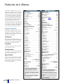
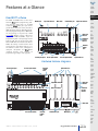
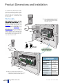
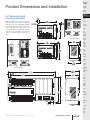
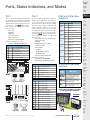
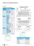
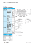
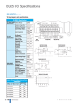
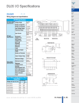
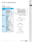
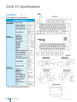
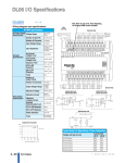
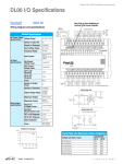
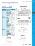
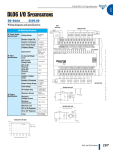
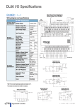
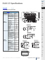
DL05 I/O Specifications
D0-05DD
Company
Information
Systems
Overview
<--->
Programmable
Controllers
Wiring diagram and specifications
Field I/O
Software
C-more &
other HMI
D0-05DD Specifications
AC Power Supply Voltage Range
Specifications
Number of Input Pts.
95-240VAC
(30VA)
Number of Commons
2 (isolated)
Input Voltage Range
12-24VDC
Input Impedance
(X0-X2) 1.8K @
12-24VDC
(X3-X7) 2.8K @
12-24VDC
DC Input
Specifications
On Current/
Voltage Level
OFF Current/
Voltage Level
Response Time
OFF to ON
Response
ON to OFF
Response
Fuses
Number of Output
Points
Number of Commons
Drives
8 (sink/source)
Soft
Starters
Motors &
Gearbox
Power
input wiring
95-240
VAC
20-28
VDC
6-27
VDC
12-24
VDC Source
>5mA/10VDC
Sink
Input point wiring
<0.5mA/<2VDC
X0-X2
X3-X7
Output point wiring
Photo
Sensors
Equivalent input circuit,
high-speed inputs (X0-X2)
Limit
Switches
Encoders
12-24
VDC
Source
None
Current
Sensors
Sink
6 (sinking)
1
Output Voltage Range
6-27VDC
Peak Voltage
50VDC
Pressure
Sensors
Equivalent input circuit,
standard inputs (X3-X7)
Temperature
Sensors
Pushbuttons/
Lights
Max.Frequency (Y0,Y1) 7kHz
DC Output
Specifications
ON Voltage Drop
0.5VDC @ 1A
Maximum Current
0.5A / point
(Y0-Y1)*
1.0A / point
(Y2-Y5)
Maximum
Leakage Current
Maximum
Inrush Current
OFF to ON Response
12-24
VDC
Source
<30µs (Y0-Y1)
<60µs (Y2-Y5)
External DC Power
Required
Status Indicators
20-28VDC 150mA
max.
Fuses
None (external
recommended)
Equivalent output circuit
standard outputs (Y2-Y5)
Equivalent output circuit
pulse outputs (Y0-Y1)
2A for 100ms10A
for 10ms
ON to OFF Response
Process
Sink
Relays/
Timers
15µA @ 30VDC
<10µs
Motor
Controls
Proximity
Sensors
<100µs <8ms
<100µs <8ms
Steppers/
Servos
20-28
VDC
20-28
VDC
Comm.
Terminal
Blocks &
Wiring
Power
Circuit
Protection
Enclosures
Tools
Logic side
Pneumatics
Derating chart for DC outputs
Safety
Appendix
Product
Index
Volume 14
w w w. a u to m a t i o n d i re c t . c o m / d l 05
Programmable Controllers
e2-37
Part #
Index
Features at a Glance
The DL05 and DL06 micro PLCs are
complete self-contained systems. The CPU,
power supply, and I/O are all included
inside the same housing. Option modules
are available to expand the capability of
each PLC family for more demanding applications. The standard features of these PLCs
are extraordinary and compare favorably
with larger and more expensive PLCs.
The specification tables to the right are
meant for quick reference only. Detailed
specifications and wiring information for
each model of the DL05 and DL06 PLCs
can be found in those specific sections.
Program capacity
Most boolean ladder instructions require a
single word of program memory. Other
instructions, such as timers, counters, etc.,
require two or more words. Data is stored in
V-memory in 16-bit registers.
Performance
The performance characteristics shown in the
tables represent the amount of time required
to read the inputs, solve the Relay Ladder
Logic program and update the outputs.
Instructions
A complete list of instructions is available
at the end of this section.
Communications
The DL05 and DL06 offer powerful
communication features normally found
only on more expensive PLCs.
Special features
The DC input and DC output PLCs offer
high-speed counting or pulse output.
Option module slots allow for discrete
I/O expansion, analog I/O, or additional
communication options.
DL05 CPU Specifications
System capacity
DL06 CPU Specifications
System capacity
Total memory available (words). . . . . . . . . . . . . . . . . . . . 6K
Ladder memory (words) . . . . . . . . . . . . . . . . . . . . . . . 2,048
V-memory (words) . . . . . . . . . . . . . . . . . . . . . . . . . . . 4,096
User V-memory . . . . . . . . . . . . . . . . . . . . . . . . . . . 3,968
Non-volatile user V-memory . . . . . . . . . . . . . . . . . . . 128
Battery backup . . . . . . . . . . . . . . . . . . . . . . . . . . . . . . . . Yes1
Total built-in I/O . . . . . . . . . . . . . . . . . . . . . . . . . . . . . . . . 14
Inputs . . . . . . . . . . . . . . . . . . . . . . . . . . . . . . . . . . . . . . . 8
Outputs. . . . . . . . . . . . . . . . . . . . . . . . . . . . . . . . . . . . . . 6
I/O expansion. . . . . . . . . . . . . . . . . . . . . . . . . . . . . . . . . Yes1
Total memory available (words) . . . . . . . . . . . . . . . . . 14.8K
Ladder memory (words). . . . . . . . . . . . . . . . . . . . . . . . 7680
V-memory (words) . . . . . . . . . . . . . . . . . . . . . . . . . . . . 7616
User V-memory . . . . . . . . . . . . . . . . . . . . . . . . . . . . 7488
Non-volatile user V-memory . . . . . . . . . . . . . . . . . . . 128
Built-in battery backup (D2-BAT-1) . . . . . . . . . . . . . . . . Yes
Total I/O . . . . . . . . . . . . . . . . . . . . . . . . . . . . . . . . . . . . . . 36
Inputs . . . . . . . . . . . . . . . . . . . . . . . . . . . . . . . . . . . . . . 20
Outputs. . . . . . . . . . . . . . . . . . . . . . . . . . . . . . . . . . . . . 16
I/O expansion . . . . . . . . . . . . . . . . . . . . . . . . . . . . . . . . Yes1
Performance
Contact execution (Boolean) . . . . . . . . . . . . . . . . . . . . 0.6µs
Typical scan (1K Boolean)2 . . . . . . . . . . . . . . . . . . . 1-2ms.
Contact execution (Boolean) . . . . . . . . . . . . . . . . . . . . 0.7µs
Typical scan (1K Boolean)2 . . . . . . . . . . . . . . . . . . 1.5-3ms.
Instructions and diagnostics
RLL ladder style . . . . . . . . . . . . . . . . . . . . . . . . . . . . . . . Yes
RLLPLUS/flowchart style (Stages) . . . . . . . . . . . . . Yes/256
Run-time editing . . . . . . . . . . . . . . . . . . . . . . . . . . . . . . . Yes
Supports Overrides. . . . . . . . . . . . . . . . . . . . . . . . . . . . . Yes
Scan . . . . . . . . . . . . . . . . . . . . . . . . . . . . . . . . Variable/fixed
Number of Instructions. . . . . . . . . . . . . . . . . . . . . . . . . . 133
Types of Instructions:
Control relays. . . . . . . . . . . . . . . . . . . . . . . . . . . . . . . 512
Timers . . . . . . . . . . . . . . . . . . . . . . . . . . . . . . . . . . . . 128
Counters. . . . . . . . . . . . . . . . . . . . . . . . . . . . . . . . . . . 128
Immediate I/O . . . . . . . . . . . . . . . . . . . . . . . . . . . . . . Yes
Subroutines . . . . . . . . . . . . . . . . . . . . . . . . . . . . . . . . Yes
For/next loops . . . . . . . . . . . . . . . . . . . . . . . . . . . . . . Yes
Timed interrupt . . . . . . . . . . . . . . . . . . . . . . . . . . . . . . Yes
Integer math . . . . . . . . . . . . . . . . . . . . . . . . . . . . . . . . Yes
Floating-point math. . . . . . . . . . . . . . . . . . . . . . . . . . . No
PID . . . . . . . . . . . . . . . . . . . . . . . . . . . . . . . . . . . . . . . Yes
Drum sequencers . . . . . . . . . . . . . . . . . . . . . . . . . . . . Yes
Bit of word . . . . . . . . . . . . . . . . . . . . . . . . . . . . . . . . . Yes
ASCII print . . . . . . . . . . . . . . . . . . . . . . . . . . . . . . . . . Yes
Real-time clock/calendar . . . . . . . . . . . . . . . . . . . . . . . . Yes1
Internal diagnostics. . . . . . . . . . . . . . . . . . . . . . . . . . . . . Yes
Password security. . . . . . . . . . . . . . . . . . . . . . . . . . . . . . Yes
System and user error log . . . . . . . . . . . . . . . . . . . . . . . . No
Communications
Built-in ports . . . . . . . . . . . . . . . . . . . . . . . . . Two RS-232C
Protocols supported:
K-sequence (proprietary protocol). . . . . . . . . . . . . . . Yes
DirectNet master/slave . . . . . . . . . . . . . . . . . . . . . . . . Yes
Modbus RTU master/slave. . . . . . . . . . . . . . . . . . . . . Yes
ASCII out . . . . . . . . . . . . . . . . . . . . . . . . . . . . . . . . . . Yes
Baud rate
Port 1. . . . . . . . . . . . . . . . . . . . . . . . 9,600 baud (fixed)
Port 2. . . . . . . . . . . . . . . . selectable 300-38,400 baud
. . . . . . . . . . . . . . . . . . . . . . . . . . . . . . . . . (default 9,600)
Specialty Features
Filtered inputs . . . . . . . . . . . . . . . . . . . . . . . . . . . . . . . . Yes3
Interrupt input . . . . . . . . . . . . . . . . . . . . . . . . . . . . . . . . Yes3
High speed counter . . . . . . . . . . . . . . . . . . . . . . . Yes, 5kHz3
Pulse output. . . . . . . . . . . . . . . . . . . . . . . . . . . . . Yes, 7kHz3
Pulse catch input . . . . . . . . . . . . . . . . . . . . . . . . . . . . . . Yes3
1- These features are available with use of
certain option modules. Option module specifications are located later in this section.
2- Our 1K program includes contacts, coils, and
scan overhead. If you compare our products to
others, make sure you include their scan overhead.
3- Input features only available on units with DC
inputs and output features only available on
units with DC outputs.
Performance
Instructions and diagnostics
RLL ladder style . . . . . . . . . . . . . . . . . . . . . . . . . . . . . . . Yes
RLLPLUS/flowchart style (Stages) . . . . . . . . . . . . Yes/1024
Run-time editing . . . . . . . . . . . . . . . . . . . . . . . . . . . . . . . Yes
Supports Overrides. . . . . . . . . . . . . . . . . . . . . . . . . . . . . Yes
Scan . . . . . . . . . . . . . . . . . . . . . . . . . . . . . . . . Variable/fixed
Number of Instructions. . . . . . . . . . . . . . . . . . . . . . . . . . 229
Types of Instructions:
Control relays . . . . . . . . . . . . . . . . . . . . . . . . . . . . . 1024
Timers . . . . . . . . . . . . . . . . . . . . . . . . . . . . . . . . . . . . 256
Counters. . . . . . . . . . . . . . . . . . . . . . . . . . . . . . . . . . . 128
Immediate I/O . . . . . . . . . . . . . . . . . . . . . . . . . . . . . . Yes
Subroutines . . . . . . . . . . . . . . . . . . . . . . . . . . . . . . . . Yes
For/next loops . . . . . . . . . . . . . . . . . . . . . . . . . . . . . . Yes
Table functions . . . . . . . . . . . . . . . . . . . . . . . . . . . . . . Yes
Timed interrupt . . . . . . . . . . . . . . . . . . . . . . . . . . . . . . Yes
Integer math . . . . . . . . . . . . . . . . . . . . . . . . . . . . . . . . Yes
Trigonometric functions . . . . . . . . . . . . . . . . . . . . . . . Yes
Floating-point math . . . . . . . . . . . . . . . . . . . . . . . . . . Yes
PID . . . . . . . . . . . . . . . . . . . . . . . . . . . . . . . . . . . . . . . Yes
Drum sequencers . . . . . . . . . . . . . . . . . . . . . . . . . . . . Yes
Bit of word . . . . . . . . . . . . . . . . . . . . . . . . . . . . . . . . . Yes
Number type conversion . . . . . . . . . . . . . . . . . . . . . . Yes
ASCII in, out, print . . . . . . . . . . . . . . . . . . . . . . . . . . . Yes
LCD instruction . . . . . . . . . . . . . . . . . . . . . . . . . . . . . Yes
Real-time clock/calendar . . . . . . . . . . . . . . . . . . . . . . . . Yes
Internal diagnostics. . . . . . . . . . . . . . . . . . . . . . . . . . . . . Yes
Password security. . . . . . . . . . . . . . . . . . . . . . . . . . . . . . Yes
System and user error log . . . . . . . . . . . . . . . . . . . . . . . . No
Communications
Built-in ports:. . . . . . . . . . . . . . . . . . . . . . . . . One RS-232C
. . . . . . . . . . One multi-function RS232C/RS422/RS485
NOTE: RS485 is for MODBUS RTU only.
Protocols supported:
K-sequence (proprietary protocol). . . . . . . . . . . . . . . Yes
DirectNet master/slave . . . . . . . . . . . . . . . . . . . . . . . . Yes
Modbus RTU master/slave. . . . . . . . . . . . . . . . . . . . . Yes
ASCII in/out . . . . . . . . . . . . . . . . . . . . . . . . . . . . . . . . Yes
Baud rate
Port 1. . . . . . . . . . . . . . . . . . . . . . . . 9,600 baud (fixed)
Port 2. . . . . . . . . . . . . . . . selectable 300-38,400 baud
. . . . . . . . . . . . . . . . . . . . . . . . . . . . . . . . . (default 9,600)
Specialty Features
Filtered inputs . . . . . . . . . . . . . . . . . . . . . . . . . . . . . . . . Yes3
Interrupt input . . . . . . . . . . . . . . . . . . . . . . . . . . . . . . . . Yes3
High speed counter . . . . . . . . . . . . . . . . . . . . . . . Yes, 7kHz3
Pulse output. . . . . . . . . . . . . . . . . . . . . . . . . . . . Yes, 10kHz3
Pulse catch input . . . . . . . . . . . . . . . . . . . . . . . . . . . . . . Yes3
1- These features are available with use of
certain option module. Option module specifications are located later in this section.
2- Our 1K program includes contacts, coils, and
scan overhead. If you compare our products to
others, make sure you include their scan overhead.
3- Input features only available on units with DC
inputs and output features only available on
units with DC outputs.
Volume 14
e2-20
Programmable Controllers
1 - 80 0 - 633 - 0405
Features at a Glance
Company
Information
Systems
Overview
DirectSOFT software
The DL05 and DL06 PLCs use the same
familiar DirectSOFT programming software that our larger PLCs use. A FREE
version of DirectSOFT gives you all the
great features of the full version, but with a
100-word PLC program download limitation. For programs larger than 100 words,
the full package is required. The FREE
PC-DS100 software may be sufficient to
program the DL05 and DL06. If you are
programming with a full package version
prior to v5.0, you will need v2.4 or later
for the DL05 PLCs and v4.0 or later for the
DL06. We always recommend the latest
version for the most robust features. See
the Software section in this catalog for a
complete description of DirectSOFT
including features, part numbers of
programming packages and upgrades.
Programmable
Controllers
Mounting tab
Input status indicators
Mode switch
Communication ports
Output status indicators
Software
C-more &
other HMI
Drives
Mode status
indicators
Communication status
indicators
Removable
terminal
block
External power inputs
Discrete input terminals
Discrete output terminals
Option module slot
Hardware features diagrams
External power inputs
Field I/O
Discrete output terminals
Removable
terminal
block
Soft
Starters
Motors &
Gearbox
Steppers/
Servos
Motor
Controls
Proximity
Sensors
Photo
Sensors
Limit
Switches
Encoders
Current
Sensors
Option module slots
Pressure
Sensors
Temperature
Sensors
Pushbuttons/
Lights
Mode status
indicators
Output status indicators
Input status indicators
Communication status
indicators
Process
Relays/
Timers
Comm.
Terminal
Blocks &
Wiring
Power
Circuit
Protection
Mode switch
Enclosures
Tools
Pneumatics
Discrete input terminals
Removable
terminal
block
Communication ports
Safety
Mounting tab
Appendix
Product
Index
Volume 14
w w w. a u to m a t i o n d i re c t . c o m
Programmable Controllers
e2-21
Part #
Index
Product Dimensions and Installation
It is important to understand the installation requirements for your DL05 or DL06
system. Your knowledge of these requirements will help ensure that your system
operates within its environmental and
electrical limits.
Plan for safety
Note: there is a minimum clearance requirement of
2" (51mm) between the panel door (or any
devices mounted in the panel door) and the
nearest DL05 component.
This catalog should never be used as a
replacement for the user manual. You can
purchase, download free, or view online
the user manuals for these products. The
D0-USER-M is the publication for the
DL05 PLCs, and the D0-06USER-M is the
publication for the DL06 PLCs. The
D0-OPTIONS-M is the user manual for
the option modules. These user manuals
contain important safety information that
must be followed. The system installation
should comply with all appropriate electrical codes and standards.
Temperature probe
2"
50mm
min
Power source
2"
50mm
min
2"
50mm
min
Panel ground terminal
Bus b
ar
Panel
Ground braid copper lugs
Star washers
Star washers
Earth
ground
Panel or single
point ground
See the Enclosure
section to find an enclosure
that fits your application
Temperature probe
1.5"
38mm
min
Environmental Specifications
for DL05 and DL06
Power source
1.5"
38mm
min
Panel ground terminal
Bus b
ar
Earth
ground
Note: There is a minimum clearance requirement of 1.5"
(38mm) between the panel door (or any devices mounted
in the panel door) and the nearest DL06 component.
1.5"
38mm
min
Storage Temperature
-4º F-158ºF
(-20ºC to 70ºC)
Ambient Operating
Temperature
32ºF-131ºF
(0º to 55ºC)
Ambient Humidity
5 to 95% relative
humidity
(non-condensing)
Vibration Resistance
MIL STD 810C
Method 514.2
Shock Resistance
MIL STD 810C
Method 516.2
Noise Immunity
NEMA (ICS3-304)
Atmosphere
No corrosive gases
Volume 14
e2-22
Programmable Controllers
1 - 80 0 - 633 - 0405
Product Dimensions and Installation
Company
Information
Systems
Overview
Programmable
Controllers
Unit dimensions and
mounting orientation
Field I/O
DL05 and DL06 PLCs must be mounted
properly to ensure ample airflow for
cooling purposes. It is important to follow
the unit orientation requirements and to
verify that the PLC’s dimensions are
compatible with your application. Notice
particularly the grounding requirements
and the recommended cabinet clearances.
Software
C-more &
other HMI
Drives
Soft
Starters
Motors &
Gearbox
Mounting orientation
Steppers/
Servos
Motor
Controls
Proximity
Sensors
Photo
Sensors
Limit
Switches
Encoders
Current
Sensors
Pressure
Sensors
Temperature
Sensors
Mounting orientation
Pushbuttons/
Lights
Process
Relays/
Timers
Comm.
Terminal
Blocks &
Wiring
Power
Circuit
Protection
Enclosures
Tools
Pneumatics
Safety
Appendix
Product
Index
Volume 14
w w w. a u to m a t i o n d i re c t . c o m
Programmable Controllers
e2-23
Part #
Index
Ports, Status Indicators, and Modes
Port 1
Port 1 is a 6-pin, fixed configuration port and
has the same pin assignments on the DL05
and the DL06. Please refer to the table and
diagrams on this page. This port can be used
to connect to an HPP, DirectSOFT, an operator interface, or other external device.
Features include:
• 9600 baud
• 8 data bits
• Odd parity
• 1 start bit, 1 stop bit
• Station address of 1
• Asynchronous, half-duplex, DTE
Protocols supported (as slave):
• K sequence, DirectNET, Modbus RTU
DL05 & DL06 Port 1 Pin Descriptions
1
2
3
4
5
6
0V
Power (-) connection (GND)
5V
Power (+) connection
RXD
Receive data (RS-232C)
TXD
Transmit data (RS-232C)
5V
Power (+) connection
0V
Power (-) connection (GND)
Port 2
Port 2 is a configurable port on both the
DL05 and the DL06 PLCs. The DL05 PLC
uses a 6-pin modular connector and offers
RS-232 communications only. The DL06
PLC uses a 15-pin HD-sub connector and
offers RS-232, RS-422, or RS-485
communications. Please refer to the table
and diagrams on this page for more information. This port can be used to connect
to an HPP, DirectSOFT, an operator interface, or other external device. Features of
port 2 include:
• 300, 600, 1200, 2400, 4800, 9600 (default),
19,200, 38,400 baud
• 8 data bits
• Odd (default), even, or no parity
• 1 start bit, 1 stop bit
• Station address:
1 (default)
1-90 DirectNET, K sequence
1-247 Modbus RTU
• Asynchronous, half-duplex, DTE
Protocols supported:
• K sequence (slave), DirectNET
(master/slave), Modbus (master/slave)
DL05 Port 2 Pin Descriptions
1
2
3
4
5
6
DL05
0V
Power (-) connection (GND)
5V
Power (+) connection
RXD
Receive data (RS-232C)
TXD
Transmit data (RS-232C)
RTS
Ready to send
0V
Power (-) connection (GND)
DL06 Port 2 Pin Descriptions
6-pin Female Modular Connector
DL06
6-pin Female
Modular Connector
1
2
3
4
5
6
7
8
9
10
11
12
13
14
15
5V
Power (+) connection
TXD
Transmit data (RS-232C)
RXD
Receive data (RS-232C)
RTS
Ready to send (RS232C)
CTS
Clear to send (RS232C)
RXD-
Receive data (-) (RS-422/485)
0V
Power (-) connection (GND)
0V
Power (-) connection (GND)
Company
Information
DL05 and DL06 status
indicators
Status Indicators
RUN
CPU
ON
Power good
OFF
Power failure
ON
CPU is in Run Mode
OFF
CPU is in Stop or Program Mode
ON
CPU self diagnostics error
OFF
CPU self diagnostics good
ON
Data is being transmitted by the
CPU-Port 1
OFF
No data is being transmitted by
the CPU-Port 1
ON
Data is being received by the
CPU-Port 1
OFF
No data is being received by the
CPU-Port 1
ON
Data is being transmitted by the
CPU-Port 2
OFF
No data is being transmitted by
the CPU-Port 2
ON
Data is being received by the
CPU-Port 2
OFF
No data is being received by the
CPU-Port 2
TX1
RX1
TX2
RX2
CPU Action
CPU is forced into the RUN mode if no
RUN (Run errors are encountered. No program
Program) changes are allowed by the program-
ming/monitoring device.
RUN PROGRAM and the TEST modes
TERM
are available. Mode and program
(Terminal) changes are allowed by the programSTOP
ming/monitoring device.
CPU is forced into the STOP mode. No
changes are allowed by the programming/monitoring device.
Use the optional low profile 15-pin adapter
to make option module wiring easier.
D0-06ADPTR
Transmit data (-) (RS-422/485)
RTS+
Ready to send (+) (RS-422/485)
RTS-
Ready to send (-) (RS-422/485)
Motors &
Gearbox
Steppers/
Servos
Motor
Controls
Proximity
Sensors
Photo
Sensors
Limit
Switches
Encoders
Current
Sensors
Pressure
Sensors
Temperature
Sensors
Pushbuttons/
Lights
Process
Relays/
Timers
Comm.
Terminal
Blocks &
Wiring
Power
Circuit
Protection
Enclosures
Safety
Appendix
CTS+ Clear to send (+) (RS-422/485)
Product
Index
Clear to send (-) (RS-422/485)
15-pin Female
D-sub Connector
Volume 14
w w w. a u to m a t i o n d i re c t . c o m
Soft
Starters
Pneumatics
RXD+ Receive data (+) (RS-422/485)
CTS-
Software
Tools
TXD+ Transmit data (+) (RS-422/485
TXD-
Field I/O
Drives
DL05 and DL06 mode
switches
Mode
Switch
Position
Programmable
Controllers
C-more &
other HMI
Indicator Status Meaning
PWR
Systems
Overview
Programmable Controllers
e2-27
Part #
Index