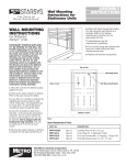
1
Metro™ Series
Mobile Computing Workstations
MPE-7800 Series
Nickel Metal Hydride
Power Supply
Operations Manual Supplement
L01-504, RevA
Copyright © 2013
InterMetro Industries Corporation
www.metro.com
THIS PAGE INTENTIONALLY LEFT BLANK
Notice:
InterMetro Industries Corporation reserves the right to make improvements or changes in the products described in this manual at
any time without notice.
While reasonable efforts have been made in the preparation of this document to assure its accuracy, InterMetro Industries
Corporation assumes no liability resulting from any errors or omissions in this document, or from the use of the information
contained herein.
Copyright Notice:
This manual is copyrighted. All rights reserved. This manual may be printed for personal use only. This manual, whole or in part,
may not be copied, photocopied, reproduced, translated, or reduced to any electronic medium or machine-readable form for
distribution. This manual, whole or in part, may not be modified without prior consent, in writing, from InterMetro Industries
Corporation.
Copyright © 2013 by InterMetro Industries Corporation, 651 North Washington Street, Wilkes-Barre, PA 18705, U.S.A.
•
•
Metro is a registered trademark of InterMetro Industries Corporation.
Windows is a registered trademark of Microsoft Corporation in the United States and other countries.
Contact Information:
InterMetro Industries Corporation
North Washington Street
Wilkes-Barre, PA 18705
Phone: 1-800-992-1776
http://www.metro.com/support
FCC Information:
This device complies with FCC Rules, part 15. Operation is subject to the following conditions:
1.
2.
Notice:
Warning:
This device may not cause harmful interference, and
This device must accept any interference that may be received, including interference that may cause undesired
operation.
This equipment has been tested and found to comply with the limits for a Class A digital device, pursuant to part 15 of the
FCC rules. These limits are designed to provide reasonable protection against harmful interference when the equipment
is operated in a commercial environment. This equipment generates, uses, and can radiate radio frequency energy and,
if not installed and used in accordance with the instruction manual, may cause harmful interference to radio
communications. Operation of this equipment in a residential area is likely to cause harmful interference in which case
the user will be required to correct the interference at the user’s expense.
Changes or modifications to this device not expressly approved by InterMetro Industries Corporation could void the
user’s authority to operate this equipment.
Shielded cables must be used with this unit to ensure compliance with the FCC Class A limits.
Industry Canada:
This class A digital apparatus meets all requirements of the Canadian Interface Causing Equipment Regulations. Operation is
subject to the following two conditions:
1.
2.
This device may not cause harmful interference, and
This device must accept any interference received, including interference that may cause undesired operation.
Regulatory Compliance
This system was tested and complies with UL 60601-1, CAN/CSA C22.22 No.601.1 and IEC/EN 60601-1-1 medical safety
standards.
MetroTM MPE-7800 Series NiMH Power Supply Operations Manual Supplement, Doc. No. L01-504
InterMetro Industries Corporation
3
Symbol Explanations
The product is CSA certified with respect to electrical shock, fire and mechanical hazards only
in accordance with UL 60601-1, CAN/CSA C22.22 No.601.1 and IEC/EN 60601-1-1 as Type B
Patient Care Medical Equipment suitable for use in patient vicinity.
Attention, consult accompanying documents
Important Safety Instructions
This document contains important safety and operating instructions for the MPE-7800 series Power Supply. Please read all
instructions and cautionary markings before putting it into service on a Mobile Computing Workstation.
Caution:
User maintenance consists of cleaning, periodic tightening of fasteners and the like. For safety purposes, any and all
servicing other than the procedures detailed in the Maintenance section of this manual must be performed by qualified
service personnel only. For all service items, please contact InterMetro Customer Service.
Caution:
TM
Do not operate an MPE-7800 series Power Supply or associated Metro Series Mobile Computing Workstation if
either has received a severe impact, been knocked over, fallen down stairs, or otherwise been physically damaged.
Please have a qualified service person inspect both the Mobile Computing Workstation and the Power Supply for any
performance or safety hazard prior to putting it back into service.
Caution:
Ensure that the AC power supply cord is located and secured so that it will not be stepped on, tripped over, or
otherwise subjected to damage or stress. Please secure the AC power cord plug in the retaining clips provided on the
Mobile Computing Workstation when it is unplugged from the AC outlet in order to prevent accidental tripping and
physical damage to the cord plug or electrical insulation.
To prevent damage to any cords or connectors when disconnecting, always grasp and pull by the connector and not
the cord.
Do not operate the Power Supply or Mobile Computing Workstation with damaged cords or connectors. Please
replace the damaged component immediately. Contact InterMetro Customer Service for replacement parts and
service.
Caution:
To reduce the risk of electric shock, unplug the Power Supply AC cord from an AC outlet and switch the ON/Extended
Storage Switch to the Extended Storage (OFF) position before attempting any maintenance or cleaning. Turning off
computers or disconnecting the AC power cord alone will not reduce the risk of electric shock because the Power
Supply is internally powered by a battery.
Warning: Risk of Electric Shock
TM
The AC power cord is the only means to disconnect the Power Supply and Metro Series Mobile Computing
Workstation from the AC power grid (mains). The ON/Extended Storage Switch on the Power Supply does not
disconnect from main power.
On the other side, the Power Supply employs a Nickel Metal Hydride (NiMH) battery to provide mobile DC output
power. Low voltage (10-16 VDC) DC power is available from the Power Supply even when the AC cord is
disconnected from an AC outlet. To remove DC power, put the ON/Extended Storage Switch in the Extended Storage
(OFF) position.
DANGER: Risk of Explosion
The Mobile Computing Workstation and the Power Supply are not for use in hazardous (classified) locations. Do not
use the Mobile Computing Workstation, nor recharge the Power Supply battery, in oxygen enriched areas; areas
where flammable anesthetics are used or stored; or any other hazardous, classified location.
4
MetroTM MPE-7800 Series NiMH Power Supply Operations Manual Supplement
InterMetro Industries Corporation
Caution (USA 240 V):
If an MPE-7800 series Power Supply is connected to a 240 V supply system in the United States of America (USA), it
shall be a center tapped single phase supply circuit.
Electromagnetic Interference (EMI) Recommendations
This equipment generates, uses and can radiate radio frequency energy and, if not installed and used in accordance with the
instructions, may cause harmful interference to other devices in the vicinity. However, there is no guarantee that interference will
not occur in a particular installation. If this equipment does not cause harmful interference to other devices, which can be
determined by turning the equipment off and on, the user is encouraged to try to correct the interference by one or more of the
following measures:
•
•
•
•
Reorient or relocate the receiving device.
Increase the separation between the equipment.
Connect the equipment to an outlet on a circuit different from that to which the other device(s) are connected.
Consult the manufacturer or field service technician for help.
MetroTM MPE-7800 Series NiMH Power Supply Operations Manual Supplement, Doc. No. L01-504
InterMetro Industries Corporation
5
Revision History
REV/
Issue
Revision Description
Date
Approved
A
Initial Release
11/30/2009
V. Bowman
B
1. Change in company contact information
2. Update in cart label graphic
11/17/2010
V. Bowman
L01504,
RevA
1) As per Metro Standards this Operations Manual is assigned
with new Commodity Code L01-504 with Initial Release as
RevA with effective from 01/09/2013.
2) Previous nomenclature of this document is 402545 RevB
MPE7800 NiMH PS Operations Manual
3) Updated references in Page 9.
4) All above revisions remain valid in L01-504 RevA.
01/09/2013
Paul Prickett
6
MetroTM MPE-7800 Series NiMH Power Supply Operations Manual Supplement
InterMetro Industries Corporation
Table of Contents
References ...................................................................................................................... 9 Introduction ................................................................................................................... 10 Mobile Rechargeable Power Supply ....................................................................................................... 10 Power Supply Status................................................................................................................................ 11 Features ................................................................................................................................................... 12 Equipment Classification ........................................................................................................................ 13 Important Product Notices....................................................................................................................... 13 Disposal ................................................................................................................................................... 13 Getting Started .............................................................................................................. 14 Installation ............................................................................................................................................... 14 Charging the Power Supply Battery ........................................................................................................ 14 Powering Up the MPE-7800 NiMH Power Supply ................................................................................ 15 Starting BatteryPro .................................................................................................................................. 16 BatteryPro Settings .................................................................................................................................. 16 Terminating BatteryPro ........................................................................................................................... 17 Operation ...................................................................................................................... 18 Power Supply Location on the MetroTM Series Mobile Computing Workstation ................................... 18 Powering Up the MPE-7800 NiMH Power Supply ................................................................................ 19 Remote Fuel Gauge ................................................................................................................................. 19 Starting BatteryPro Application .............................................................................................................. 22 BatteryPro Status Indications .................................................................................................................. 23 BatteryPro Configuration and Status ....................................................................................................... 27 MPE-7800 Power Supply System Installation ............................................................... 37 Hardware Installation .............................................................................................................................. 37 Software Installation ............................................................................................................................... 39 Maintenance and Storage ............................................................................................. 51 Cleaning .................................................................................................................................................. 51 Power Supply Air Filter .......................................................................................................................... 51 MetroTM MPE-7800 Series NiMH Power Supply Operations Manual Supplement, Doc. No. L01-504
InterMetro Industries Corporation
7
Fuse Replacement ................................................................................................................................... 57 Storage and Transport Conditions ........................................................................................................... 57 Troubleshooting ...................................................................................................................................... 58 Technical Specifications ................................................................................................ 63 Contacting InterMetro Industries Corporation................................................................ 64 InterMetro Industries Corporation Contact Information ......................................................................... 64 InterMetro Customer Service .................................................................................................................. 64 Repair ...................................................................................................................................................... 64 8
MetroTM MPE-7800 Series NiMH Power Supply Operations Manual Supplement
InterMetro Industries Corporation
References
Document
Number
Title
L01-502
MetroTM 1700 Series Mobile Computing Workstation Operations Manual
L01-503
MetroTM 1800 Series Mobile Computing Workstation Operations Manual
MetroTM MPE-7800 Series NiMH Power Supply Operations Manual Supplement, Doc. No. L01-504
InterMetro Industries Corporation
9
Introduction
Mobile Rechargeable Power Supply
The MetroTM MPE-7800 Nickel Metal Hydride (NiMH) Power Supply is a rechargeable power
source for the MetroTM Series Mobile Computing Workstations. The MetroTM NiMH Power
Supply is a fully automatic power supply charger system with a nominal DC output voltage of
14.4 Volts (V) and a battery capacity of 500 Watt-hours (Wh). When it is plugged into an AC
outlet, it supplies the Mobile Computing Workstation system equipment while also charging the
NiMH cells. When unplugged from the outlet, the power supply switches automatically to supply
the workstation equipment from the internal NiMH rechargeable battery cells. The power supply
is designed for continuous operation and service is not interrupted by plugging in or unplugging
the power supply.
MPE-7800 with Fan Filter
MPE-7800 without Fan Filter
10
MetroTM MPE-7800 Series NiMH Power Supply Operations Manual Supplement
InterMetro Industries Corporation
Power Supply Status
The status of the MPE-7800 series Power Supply is displayed by a remote Fuel Gauge display
and optionally on the workstation monitor by the Metro BatteryPro software.
Remote Fuel Gauge Display
The remote Fuel Gauge is embedded in the MetroTM Series Mobile Computing Workstation
monitor mount at eye level height and is connected to the power supply. It displays the battery
charge level and state with a series of LED indicators.
Remote Fuel Gauge Display
BatteryPro Mobile Computing Workstation Power Supply Management Software
In a manner similar to notebook computer battery monitors, BatteryPro Mobile Computing
Workstation Power Supply Management Software displays the MPE-7800 series Power Supply
status, battery level as a percentage, and calculated remaining run time. The status is
displayed on the Workstation display monitor using the Windows task bar and control panels.
BatteryPro also alerts the user when the power supply batteries are reaching the end of the
discharge cycle so that the user can perform any one of three actions:
1. Save any work and shut down the system.
2. Allow the computer to shut down in an orderly manner with all data quickly stored onto
the hard drive for Hibernation.
3. Plug the power supply into a wall outlet to start charging the unit.
BatteryPro requires a USB connection from the USB port on the Power Supply to the MetroTM
Series Mobile Computing Workstation computer.
The BatteryPro application features a status icon on the Windows taskbar and a status window.
A BatteryPro dialog (see below) can be opened to configure the power scheme and notifications
and view more detail status of the power supply system. A diagnostic tool can also be
accessed through the BatteryPro dialog.
MetroTM MPE-7800 Series NiMH Power Supply Operations Manual Supplement, Doc. No. L01-504
InterMetro Industries Corporation
11
Flo BatteryPro Dialog
BatteryPro also provides the drivers needed for access across the network for MetroTM
Dashboard.
Features
The MetroTM MPE-7800 NiMH Power Supply features:
12
•
Rugged, steel construction – built to last.
•
Remote Fuel Gauge at the user’s eye level.
•
NiMH, 500 Wh capacity rechargeable batteries.
•
Fits conveniently in the base of the MetroTM Series Mobile Computing Workstations.
•
Software application Flo BatteryPro provides the power supply status on the MetroTM
Series Mobile Computing Workstations monitor display.
o
Status icon on Windows taskbar
o
Desktop status window
o
BatteryPro dialog to configure settings and view diagnostic data.
o
Accessible across network by MetroTM Dashboard application.
•
Compatible with MetroTM 1700 and 1800 series Mobile Computing Workstations.
•
Standard USB connection between MPE-7800 Series Power Supply and workstation
computer.
•
User manual supplement included.
MetroTM MPE-7800 Series NiMH Power Supply Operations Manual Supplement
InterMetro Industries Corporation
Equipment Classification
The MetroTM MPE-7800 Series NiMH Power Supply is CSA certified with respect to electric
shock, fire and mechanical hazards only in accordance with UL 60601-1, CAN/CSA 22.2 No.
601.1 and IEC/EN 60601-1-1 as Type B Patient Care Medical Equipment suitable for use in
patient vicinities.
The MPE-7800 Series NiMH Power Supply is a Class I Equipment that is also internally
powered.
According to the degree of protection against electric shock, it is a Type B applied part.
According to the degree of protection against ingress of water the MPE-7800 Series NiMH
Power Supply is considered ordinary.
Warning:
Risk of Explosion
The MPE-7800 Series NiMH Power Supply is not suitable for use in the presence of
a flammable anesthetic mixture with air or with oxygen or nitrous oxide.
The MPE-7800 Series NiMH Power Supply is suitable for continuous operation.
Important Product Notices
The MPE-7800 Series NiMH Power Supply is a subsystem component of the MetroTM 1700 and
1800 Series Mobile Computing Workstations. Please refer to the respective User Guide for the
Mobile Computing Workstation to which the Power Supply is attached for additional information.
The MetroTM MPE-7800 Series NiMH Power Supply is only CSA certified if the equipment is left
in its original configuration as shipped from InterMetro Industries Corporation. If the user alters
the power supply by changing components on or adding components to the power supply, this
will void the CSA certification of the power supply and the Mobile Computing Workstation and is
expressly prohibited by InterMetro Industries Corporation.
The Power Supply used is provided with a “Hospital Grade” or “Hospital Only” attachment plug
for connection to the AC supply circuit.
To ensure equipment grounding reliability, the Power Supply should only be connected to AC
outlet receptacles which are marked “Hospital Grade” or “Hospital Only”. Where the integrity of
the external protective earth connector arrangement is in doubt, equipment shall be operated
from its internal electrical power source.
Disposal
Steel sections of the power supply can be disposed of or recycled.
NiMH batteries shall be recycled through Rechargeable Battery Recycling Corporation
(www.call2recycle.org; 1-877-2-RECYCLE).
Electronic components, printed circuit boards, etc., shall be disposed of in accordance with
local, state and federal regulations.
For further information call InterMetro Customer Service.
MetroTM MPE-7800 Series NiMH Power Supply Operations Manual Supplement, Doc. No. L01-504
InterMetro Industries Corporation
13
Getting Started
Installation
In general, the MetroTM MPE-7800 Series NiMH Power Supply is provided already installed on a
MetroTM Mobile Computing Workstation and is ready for use after fully charging the batteries.
The MPE-7800 Series NiMH Power Supply System can be retrofitted or installed new on a
MetroTM Mobile Computing Workstation. The power supply is self-contained and is attached
using the correct mounts on the bottom of the MetroTM Mobile Computing Workstation base.
BatteryPro is ready to install on the workstation computer. Instructions for installing an MPE7800 Series Power Supply and BatteryPro are provided in “MPE-7800 Power Supply System
Installation” below.
Unpacking
If ordered separately, the MPE-7800 Series NiMH Power Supply will arrive
fully assembled and fully functional at the customer’s site in a cardboard
box. After cutting open the box, lift the MPE-7800 out of the box.
Inspection
After the MPE-7800 Series NiMH Power Supply has been unpacked, the
user should inspect the unit for any shipping damage. If there is any
damage, please contact InterMetro Customer Service immediately.
Charging the Power Supply Battery
Before placing a MetroTM Series Mobile Computing Workstation into service for the first time
with the MPE-7800 Series NiMH Power Supply, the power supply battery should be initially
charged for a full 24 hours. To charge the battery, plug the coiled AC power cord into an AC
outlet and put the ON/Extended Storage Switch into the “ON” position (see “Powering Up the
MPE-7800 NiMH Power Supply” below). For further information on the charge indicator lights of
the Remote Fuel Gauge, please refer to the “Remote Fuel Gauge” section below.
After the initial charge, a completely discharged battery can fast charge in 3 to 3.5 hours to 95%
of battery capacity, and then top off the batteries within 3 more hours.
The MPE-7800 NiMH Power Supply must undergo a break-in period in order to realize the full
battery capacity. The break-in period is usually the first 5 charge/discharge cycles. During the
break-in period, the user may experience shorter runtimes than expected.
14
MetroTM MPE-7800 Series NiMH Power Supply Operations Manual Supplement
InterMetro Industries Corporation
Powering Up the MPE-7800 NiMH Power Supply
The MPE-7800 Series NiMH Power Supply is controlled by the “ON/Extended Storage” Switch
located on the side of the unit.
ON/Extended
Storage Switch
In the “ON” position, the power supply provides power to the MetroTM
Series Mobile Computing Workstation systems. If the workstation is not
used for an extended period of time, the ON/Extended Storage Switch
should be put in the “Extended Storage” (OFF) position. The switch
position disconnects the battery from any internal or external equipment
and avoids deep discharges of the battery, which can cause damage to
the battery.
ON/Extended Storage Switch
Warning: Risk of Electric Shock
The Power Supply employs a Nickel Metal Hydride (NiMH) battery to
provide mobile DC output power. Low voltage (11-16 VDC) DC power
is available from the Power Supply even when the AC cord is
disconnected from an AC outlet. To remove DC power, put the
ON/Extended Storage Switch in the “Extended Storage” position.
MetroTM MPE-7800 Series NiMH Power Supply Operations Manual Supplement, Doc. No. L01-504
InterMetro Industries Corporation
15
Starting BatteryPro
BatteryPro Mobile Computing Workstation Power Supply Management Software is an optional
application for monitoring the status of the MPE-7800 Series NiMH Power Supply. When
installed, BatteryPro is typically configured to start automatically when the host computer starts
up. No additional user action is required.
Notice: BatteryPro requires the workstation computer to be connected via USB to the MPE7800 USB-B port. The connection is already made if the workstation is delivered with
the MPE-7800 and BatteryPro installed.
If BatteryPro is not running as indicated by the status tray icon shown below, it can be started by
double-clicking on the BatteryPro icon shortcut provided on the desktop by the software
installation.
Red ball with lightening bolt indicates BatteryPro is running and
power supply batteries are charging.
Battery shape indicates BatteryPro is running and power supply is
running on batteries (example shown is fully charged state).
If BatteryPro is not running, double-click on the desktop shortcut to
start BatteryPro.
Notice: BatteryPro shortcut is also available from the Windows
Start All Programs menu.
Notice: The first time BatteryPro is launched, the Windows Firewall may ask you if you want to
continue to block BatteryPro. If this happens, click the “Unblock” button.
BatteryPro Settings
BatteryPro settings are configured through the BatteryPro dialog. The BatteryPro dialog is
entered by right-clicking on the BatteryPro status tray icon, highlighting (with the mouse pointer)
and selecting “Power Options …” with a left click.
Right click on BatteryPro status Tray icon and select “Power
Options …” to enter BatteryPro configuration dialog.
16
MetroTM MPE-7800 Series NiMH Power Supply Operations Manual Supplement
InterMetro Industries Corporation
The tabs in the BatteryPro dialog shown below may be selected to view and configure the
BatteryPro settings. See the section “BatteryPro Configuration and Status” below.
Flo BatteryPro Dialog
Terminating BatteryPro
BatteryPro can be stopped by right-clicking on the BatteryPro400 status tray icon, highlighting
(with the mouse pointer) and selecting “Exit” with a left click.
Right click on BatteryPro status tray icon and select and left click
on “Exit” to stop BatteryPro.
MetroTM MPE-7800 Series NiMH Power Supply Operations Manual Supplement, Doc. No. L01-504
InterMetro Industries Corporation
17
Operation
The following section describes the basic function and operation of the MPE-7800 Series Nickel
Metal Hydride (NiMH) Power Supply System.
Power Supply Location on the MetroTM Series Mobile Computing Workstation
The MPE-7800 Series NiMH Power Supply is located in the bottom of the MetroTM Series Mobile
Computing Workstation under the Base Deck. The Remote Fuel Gauge located on the monitor
stalk and the AC Power Cord associated with the Power Supply are also indicated.
Remote Fuel Gauge
Base Deck
AC Power
Cord
Power Supply
MetroTM 1700 Series Base Showing Location of Power Supply
18
MetroTM MPE-7800 Series NiMH Power Supply Operations Manual Supplement
InterMetro Industries Corporation
Powering Up the MPE-7800 NiMH Power Supply
To turn on the Power Supply, flip the ON (Normal Operation)/Extended Storage switch located
on the side of the power supply to the “ON” (up) position.
MetroTM MPE-7800 NiMH Power Supply “ON/Extended Storage” Switch
Remote Fuel Gauge
To display the charge level of the NiMH cells when operating on DC power, a Remote Fuel
Gauge is connected to the power supply. The embedded Remote Fuel Gauge is located just
below the monitor in the stalk and gives the user the current battery status at eye level height.
Remote Fuel Gauge
If the battery is fully charged, all five (5) amber LEDs are illuminated. The LEDs always display
the battery charge level whether the computer is operating or not. As the battery looses charge,
the LEDs gradually turn off, one at a time. Once the top four LEDs are off and only the amber
LED marked “LOW” is illuminated and flashing, it is recommended to plug the AC cord into an
AC outlet as soon as possible to charge the battery.
Notice:
Once the amber LED marked “LOW” starts to flash, plug the power supply into
an AC outlet to avoid loss of system power, which may cause loss of data.
Notice:
Once the NiMH Power Supply has been plugged into an AC outlet, the Remote
Fuel Gauge two green LEDs marked “AC” and “CH” turn on.
MetroTM MPE-7800 Series NiMH Power Supply Operations Manual Supplement, Doc. No. L01-504
InterMetro Industries Corporation
19
Charge Status
Seven (7) multi color LEDs (green, amber) located on the Remote Fuel Gauge
display the charging status of the NiMH power supply.
Fuel Gauge
Status
Battery is discharging under normal, mobile operation.
Example shown is down to about 50% charge remaining.
Low battery LED flashing: plug power supply into AC
immediately.
AC indicates the power supply is plugged into the wall
AC.
CH indicates the battery is charging.
The amber LEDs will turn on in sequence to indicate the
charging status.
Example shown is up to about 50% charged.
AC indicates the power supply is plugged into the wall
AC.
The Amber LEDs indicate the battery is fully charged.
Note that the CH LED is not lit because the battery is not
being charged since the cycle is complete.
20
MetroTM MPE-7800 Series NiMH Power Supply Operations Manual Supplement
InterMetro Industries Corporation
Charge Time
Initial Charge:
Before you use the power supply for the first time, the NiMH cells should
receive a full charge of at least 8 hours.
Break-in:
The MPE-7800 NiMH Power Supply must undergo a break-in period in
order to realize the full battery capacity. The break-in period is usually the
first 5 charge/discharge cycles. During the break-in period, the user may
experience shorter runtimes than expected.
Charge cycle:
After the initial charge, a completely discharged battery will quick charge
in 3 to 3.5 hours to 95% of battery capacity. At the end of quick charge,
all 5 amber LEDs will be illuminated and the green CH (Charge) LED will
turn off. At this point, the batteries of the power supply are essentially
charged and over the next 3 hours the power supply will slowly top off the
batteries.
Notice:
Extended
Storage
If the Mobile Computing Workstation will not be used for an extended
period of time, ensure the ON/Extended Storage Switch is set to the
“Extended Storage” (OFF) position. If the power supply is left in the “ON”
position, the workstation equipment will continue to draw power and deep
discharge the battery.
Notice:
Long Term
Storage (Longer
than one week)
If the Mobile Computing Workstation is to be placed in long term storage
(longer than one week), the Power Supply should be fully charged before
placing the “ON/Extended Storage” switch in the “Extended Storage”
(OFF) position.
Warning: Risk of Electric Shock
The Power Supply employs a NiMH battery to provide mobile DC output
power. Low voltage (10-16 VDC) DC power is available from the Power
Supply even when the AC cord is disconnected from an AC outlet. To
remove DC power, put the ON/Extended Storage Switch in the “Extended
Storage” (OFF) position.
MetroTM MPE-7800 Series NiMH Power Supply Operations Manual Supplement, Doc. No. L01-504
InterMetro Industries Corporation
21
Starting BatteryPro Application
When installed, BatteryPro is typically configured to start automatically when the host computer
starts up. No additional user action is required.
Notice: BatteryPro requires the workstation computer to be connected via USB to the MPE7800 USB-B port. The connection is already made if the workstation is delivered with
the MPE-7800 and BatteryPro installed.
If BatteryPro is not running as indicated by the status tray icon shown below, it can be started by
double-clicking on the BatteryPro icon shortcut provided on the desktop by the software
installation.
Red ball with lightening bolt indicates BatteryPro is running and
power supply batteries are charging.
Battery shape indicates BatteryPro is running and power supply is
running on batteries (example shown is fully charged state).
If BatteryPro is not running, double-click on the desktop shortcut to
start BatteryPro.
Notice: BatteryPro shortcut is also available from the Windows
Start All Programs menu.
Notice: The first time BatteryPro is launched, the Windows Firewall may ask you if you want to
continue to block BatteryPro. If this happens, click the “Unblock” button.
If Windows Firewall pops up the Security Alert shown
the first time BatteryPro is launched, click the
“Unblock” button.
22
MetroTM MPE-7800 Series NiMH Power Supply Operations Manual Supplement
InterMetro Industries Corporation
BatteryPro Status Indications
BatteryPro has two ways of showing the status of the workstation power supply. Both are
shown in the lower right-hand side of the computer display, in and above the status tray.
1. An icon in the status tray shows the state of the power supply batteries.
2. The Desktop Status Window, that can be hidden or moved anywhere on the workstation
monitor display, provides brief information of the state of the power supply batteries.
Status Icon
The Status Icon in the status tray shows the charge status of the workstation power supply
batteries.
Notice: Placing the mouse pointer over the icon will reveal the charging status: the percentage
of charge in the batteries and remaining charge time to full charge.
Charging. Power supply is plugged into AC power source and
is charging the batteries.
Notice:
If message “Communications: Standby” is displayed,
the power supply is not talking to the workstation
computer. See “Troubleshooting” below.
Discharging, Full Level. Power supply is not plugged into AC
power and is running on batteries: batteries near full charge.
Battery fill level is green.
Discharging, Half Level. Power supply is not plugged into AC
power and is running on batteries: batteries near half charge.
Battery fill level is green.
Discharging, ¼ Level. Power supply is not plugged into AC
power and is running on batteries: batteries near ¼ charge.
Battery fill level is yellow.
Notice:
A “Low Battery Alert” message may be displayed if
battery charge has dropped below threshold set for
“Low Battery Alert” (see “Alarms” below).
Discharging, Low Level. Power supply is not plugged into AC
power and is running on batteries: batteries nearly discharged.
Battery fill level is red.
Notice:
A “Critical Battery Alert” message may be displayed if
battery charge has dropped below threshold set for
“Critical Battery Alert” (see “Alarms” below).
MetroTM MPE-7800 Series NiMH Power Supply Operations Manual Supplement, Doc. No. L01-504
InterMetro Industries Corporation
23
Desktop Status Window
The BatteryPro Desktop Status Window normally appears above the status tray icon. It
provides descriptive information of the charge status of the workstation power supply batteries,
including estimated times to complete charging or until fully discharged. The Status Window will
appear when BatteryPro is started if the “Always Display Battery Status” box is checked in the
Configuration tab of the BatteryPro dialog (see “Configuration” under “BatteryPro Configuration
and Status” below).
Displaying the Desktop Status Window
The Desktop Status Window is enabled for display in two ways:
1. Open the BatteryPro dialog, select the “Configuration” tab and left click on (to check) the
“Always Display Battery Status” box (see “Configuration” under “BatteryPro Configuration
and Status” below).
2. If the Desktop Status Window is not displayed, right click on BatteryPro status tray icon and
select and left click on “Show/Hide Status Window” to display it.
Notice: Using this method to display the Desktop Status Window will not change the
“Always Display Battery Status” setting in the Configuration.
If the Desktop Status Window is not displayed, right click on
BatteryPro status tray icon and select and left click on
“Show/Hide Status Window” to display it.
Moving the Desktop Status Window
You may move the Desktop Status Window by clicking on it and holding down the left mouse
button, and then dragging it to any part of the monitor display.
Hiding the Desktop Status Window
The Desktop Status Window is hidden (disabled from display) in two ways:
1. Open the BatteryPro dialog, select the “Configuration” tab and left click on (to uncheck) the
“Always Display Battery Status” box (see “Configuration” under “BatteryPro Configuration
and Status” below).
2. If the Desktop Status Window is displayed, right click on BatteryPro status tray icon and
select and left click on “Show/Hide Status Window” to hide it.
Notice: Using this method to hide the Desktop Status Window will not change the “Always
Display Battery Status” setting in the Configuration.
If the Desktop Status Window is displayed, right click on
BatteryPro status tray icon and select and left click on
“Show/Hide Status Window” to hide it.
24
MetroTM MPE-7800 Series NiMH Power Supply Operations Manual Supplement
InterMetro Industries Corporation
Desktop Status Window Indications
Following are the indications and meanings of the Desktop Status Window.
Communications: Standby. Power supply and workstation
computer communications interrupted.
When BatteryPro starts, the power supply and computer
establish USB communications and BatteryPro performs a
charge test for status of the power supply batteries. The
status should change to one of the states below: if it does
not, the USB connection between the computer and power
supply has a problem. See “Troubleshooting” below.
Charging. Power supply is plugged into AC power source
and is charging the batteries.
Displays battery charge level as a percentage and
calculated remaining charge time.
Charged. Power supply is plugged into AC power source
and the batteries are fully charged.
Discharging, Full Level. Power supply is not plugged into
AC power and is running on batteries.
Battery charge level is displayed as a percentage and
calculated remaining run time based on the current
equipment load.
Discharging. Power supply is not plugged into AC power
and is running on batteries.
Battery charge level is displayed as a percentage and
calculated remaining run time based on the current
equipment load.
Discharging, Half Level. Power supply is not plugged into
AC power and is running on batteries: batteries near half
charge.
Battery charge level is displayed as a percentage and
calculated remaining run time based on the current
equipment load.
MetroTM MPE-7800 Series NiMH Power Supply Operations Manual Supplement, Doc. No. L01-504
InterMetro Industries Corporation
25
Discharging, ¼ Level. Power supply is not plugged into
AC power and is running on batteries: batteries near ¼
charge.
Battery charge level is displayed as a percentage and
calculated remaining run time based on the current
equipment load.
Discharging, Low Level. Power supply is not plugged into
AC power and is running on batteries.
Battery charge has dropped below threshold set for “Low
Battery Alarm” (see “Alarms” below).
Notice:
A “Low Battery Alert!” message may be displayed
if “Display Message” box is checked for the
Notification action. See “Alarm Notification and
Action Settings” in “Alarms” below.
Low Alarm Mute Button.
If the “Sound Alarm” and “Continuous” boxes have been
checked for the Notification action (see “Alarm Notification
and Action Settings” in “Alarms” below), the “Low Alarm
Mute” button will appear above the Status Window when the
“Low Battery Alarm” activates.
Click on the “Low Alarm Mute” button to stop the alarm
sound.
Discharging, Critical Level. Power supply is not plugged
into AC power and is running on nearly discharged batteries.
Battery charge has dropped below threshold set for “Critical
Battery Alarm” (see “Alarms” below).
Notice:
It is recommended that the power supply be
plugged into AC power immediately, especially if
the “Shutdown Pending” status is displayed.
Notice:
A “Critical Alert!” message may be displayed if
“Display Message” box is checked for the
Notification action. See “Alarm Notification and
Action Settings” in “Alarms” below.
Critical Alarm Mute Button.
If the “Sound Alarm” and “Continuous” boxes have been
checked for the Notification action (see “Alarm Notification
and Action Settings” in “Alarms” below), the “Critical Alarm
Mute” button will appear above the Status Window when the
“Critical Battery Alarm” activates.
Click on the “Critical Alarm Mute” button to stop the alarm
sound.
26
MetroTM MPE-7800 Series NiMH Power Supply Operations Manual Supplement
InterMetro Industries Corporation
BatteryPro Configuration and Status
BatteryPro settings are configured through the BatteryPro dialog window. The BatteryPro dialog
also displays more detailed status and diagnostic information. The tabs in the BatteryPro dialog
may be selected to configure and view the various BatteryPro settings and status:
•
Configuration: Displays and allows authorized users to change the BatteryPro Power
Scheme settings and to reveal or hide the display of the Desktop Status Window.
•
Power Meter: Displays the current summary information about the power source and
batteries.
•
Alarms: Displays and allows authorized users to change the low and critical battery alert
levels and actions settings.
•
Hibernate: Displays workstation computer disk requirements for hibernation, allows forcing
the computer into hibernation before a low battery shutdown condition occurs and contains
the feature to reveal the hidden Diagnostics tab.
•
Status: Displays power supply battery history summary and BatteryPro version.
•
Diagnosis: Hidden tab: when revealed, displays power supply firmware version and power
supply and individual battery data for troubleshooting purposes.
The following sections detail the functions of the tabs in the BatteryPro dialog.
Default Metro BatteryPro Dialog
MetroTM MPE-7800 Series NiMH Power Supply Operations Manual Supplement, Doc. No. L01-504
InterMetro Industries Corporation
27
Opening the BatteryPro Dialog Window
The BatteryPro dialog is entered by right-clicking on the BatteryPro status tray icon, highlighting
(with the mouse pointer) and selecting “Power Options …” with a left click.
The dialog may also be entered if BatteryPro is already running through one of the following
methods:
1. Double-click on the status tray icon.
2. Double-click on the BatteryPro shortcut on the desktop.
3. Select BatteryPro from the Windows Start All Programs menu.
Right click on BatteryPro status Tray icon and select “Power
Options …” to enter BatteryPro configuration dialog.
Configuration
The “Configuration” tab is the default display when the BatteryPro dialog is first displayed. The
“Configuration” tab allows setting of the BatteryPro Power Scheme and to set whether the
Desktop Status Window will always be displayed (see “Desktop Status Window” above).
Notice: Power Scheme settings are grayed out and not available when a user has been
restricted. See “()” below.
Default Configuration Tab Display
Select “Configuration” tab in BatteryPro dialog (appears
first when BatteryPro dialog is first opened).
Set the following:
1. Power Scheme Settings.
2. Always Display Battery Status
Click on “Apply” or “OK” button to apply new values.
“OK” also minimizes the dialog back to the status tray.
Click on “Cancel” button or “X” to minimize the dialog
back to the status tray icon without applying changes.
Click on another tab to view or edit other settings.
28
MetroTM MPE-7800 Series NiMH Power Supply Operations Manual Supplement
InterMetro Industries Corporation
Configuration Tab Display When User Access Is
Restricted
Select “Configuration” tab in BatteryPro dialog.
Power Scheme settings are grayed out and not available
to be changed.
Set the “Always Display Battery Status” only.
Click on “Apply” or “OK” button to apply new values.
“OK” also minimizes the dialog back to the status tray.
Click on “Cancel” button or “X” to minimize the dialog
back to the status tray icon without applying changes.
Click on another tab to view or edit other settings.
Power Scheme Setting:
The Power Scheme Setting sets two delays for when the workstation is not actively being used:
1. “Turn off monitor”:
delay until the system turns off the workstation display monitor.
2. “System Hibernates”: delay until the computer enters hibernation.
Power Scheme Setting:
Click on down arrow at right of setting to open drop
down list.
Click on desired time delay value – use right side bar to
scroll down for more values.
Click on “Apply” or “OK” button to apply new values.
“OK” also minimizes the dialog back to the status tray.
Click on “Cancel” button or “X” to minimize the dialog
back to the status tray icon without applying changes.
Click on another tab to view or edit other settings.
Always Display Battery Status checkbox:
The “Always Display Battery Status” checkbox controls the display of the Desktop Status
Window:
•
The Desktop Status Window is enabled to view immediately by left clicking on to check the
box on the Scheme tab. This performs the same function as the procedure in “Displaying
the Desktop Status Window” above.
MetroTM MPE-7800 Series NiMH Power Supply Operations Manual Supplement, Doc. No. L01-504
InterMetro Industries Corporation
29
•
The Desktop Status Window is disabled and hidden from view immediately by left clicking on
to un-check or clear the box on the Scheme tab. This performs the same function as the
procedure in “Hiding the Desktop Status Window” above.
Power Meter
Click on the “Power Meter” tab to view the current summary information about the power source
and batteries.
Power Meter Tab Display: On Batteries
Select “Power Meter” tab in BatteryPro dialog.
Shown at left is indication of running off battery.
Display includes battery specifications, calculated
run time and percent capacity of charge
remaining.
Click on “Apply” or “OK” button to apply new
values. “OK” also minimizes the dialog back to
the status tray.
Click on “Cancel” button or “X” to minimize the
dialog back to the status tray icon without
applying changes.
Click on another tab to view or edit other settings.
Power Meter Tab Display: On AC
Select “Power Meter” tab in BatteryPro dialog.
Shown at left is indication of plugged in and
running off AC and charging.
Display includes battery specifications, percent of
capacity charged and time remaining until fully
charged.
Click on “Apply” or “OK” button to apply new
values. “OK” also minimizes the dialog back to
the status tray.
Click on “Cancel” button or “X” to minimize the
dialog back to the status tray icon without
applying changes.
Click on another tab to view or edit other settings.
30
MetroTM MPE-7800 Series NiMH Power Supply Operations Manual Supplement
InterMetro Industries Corporation
Alarms
Click on the “Alarms” tab to view or allow authorized users to change low and critical battery
alert levels and actions settings. Clicking on the “Alarm Action” buttons displays additional
options for setting the messages and actions to be taken by BatteryPro when the alarms occur.
Default Alarms Tab Display
Select “Alarms” tab in BatteryPro dialog.
Set Low Battery and Critical Battery Alarm
threshold levels by:
1. Click check box to activate alarm.
2. Click on and while holding down mouse
button, drag pointer on threshold slide
bar. Percentage is battery discharge
level when the alarm will activate
Notification and perform the Action
shown.
3. Click on “Alarm Action” button to set
Alarm actions. New dialog will pop up
(see below).
Click on “Apply” or “OK” button to apply new
values. “OK” also minimizes the dialog back to
the status tray.
Click on “Cancel” button or “X” to minimize the
dialog back to the status tray icon without
applying changes.
Click on another tab to view or edit other settings.
Alarms Tab Display When User Access Is
Restricted
Alarms settings are grayed out and not available
to be changed when a user has been restricted.
Click on “Apply” or “OK” button to apply new
values. “OK” also minimizes the dialog back to
the status tray.
Click on “Cancel” button or “X” to minimize the
dialog back to the status tray icon without
applying changes.
Click on another tab to view or edit other settings.
MetroTM MPE-7800 Series NiMH Power Supply Operations Manual Supplement, Doc. No. L01-504
InterMetro Industries Corporation
31
Alarm Notification and Action Settings:
Click on “Alarm Action” button to set Alarm actions. There are separate settings for the Low
Battery and Critical Battery Alarms.
Notification settings:
Click check boxes to set type of Notification
desired. Two types are available in any
combination:
1. Sound Alarm: a Windows Default Critical
Error Program Error sound that runs one
time only or continuously if the
“Continuous” checkbox is selected.
The “Continuous” checkbox becomes
available only when Sound Alarm is
checked.
2. Display Message: a pop-up warning
message will appear on the screen. See
“Desktop Status Window” above.
Click on “OK” button to apply new value and exit
the dialog.
Click on “Cancel” button or “X” to exit dialog
without saving change to settings.
32
MetroTM MPE-7800 Series NiMH Power Supply Operations Manual Supplement
InterMetro Industries Corporation
Alarm Action setting:
Click check box to enable an Alarm action to be
performed when the alarm occurs.
Click on down arrow at right of setting to open
drop down list.
Click on desired action: Hibernate or Shutdown.
If enabled by the checkbox, the workstation
computer will perform the selected action when
the alarm level is reached.
Click on “OK” button to apply new value and exit
the dialog.
Click on “Cancel” button or “X” to exit dialog
without saving change to settings.
MetroTM MPE-7800 Series NiMH Power Supply Operations Manual Supplement, Doc. No. L01-504
InterMetro Industries Corporation
33
Hibernate
Click on the “Hibernate” tab to display disk space requirements and availability for workstation
computer hibernation and to enable immediate computer hibernation.
The hidden “Diagnostics” tab is revealed through the “Hibernate” tab by holding down the “Ctrl”
key and clicking on the Monitor icon: see “Diagnostics” below.
Hibernate Tab Display
Select “Hibernate” tab in BatteryPro dialog.
Display includes:
1. Force hibernate: click check box to
enable computer to enter hibernation
mode.
2. Available disk space and required disk
space for hibernation.
Click on “Apply” or “OK” button to apply new
values. “OK” also minimizes the dialog back to
the status tray.
Click on “Cancel” button or “X” to minimize the
dialog back to the status tray icon without
applying changes.
Click on another tab to view or edit other settings.
Notice:
34
While holding down “Ctrl” key, click on
Monitor icon in upper left of dialog to
reveal hidden “Diagnostics” tab.
MetroTM MPE-7800 Series NiMH Power Supply Operations Manual Supplement
InterMetro Industries Corporation
Status
Click on the “Status” tab to view a quick glance summary of the power supply battery history
and the BatteryPro version.
Status Tab Display
Select “Status” tab in BatteryPro dialog.
Display includes power supply battery
information:
1.
Charge cycle history
2.
Estimated capacity
Display also includes current BatteryPro software
version.
Click on “Apply” or “OK” button to apply new
values. “OK” also minimizes the dialog back to
the status tray.
Click on “Cancel” button or “X” to minimize the
dialog back to the status tray icon without
applying changes.
Click on another tab to view or edit other settings.
Diagnostics
When revealed, clicking on the “Diagnostics” tab provides a running list of power supply and
battery data for troubleshooting purposes. The “Diagnostics” tab is advanced functionality not
meant for the general user.
Notice: The hidden BatteryPro “Diagnostics” tab is revealed by holding down the “Ctrl” key and
clicking on the Monitor icon in the “Hibernate” tab display: see “Hibernate” above.
Reveal Diagnostics Tab
Select “Hibernate” tab in BatteryPro dialog.
While holding down “Ctrl” key, click on Monitor
icon in upper left of dialog to reveal hidden
“Diagnostics” tab.
MetroTM MPE-7800 Series NiMH Power Supply Operations Manual Supplement, Doc. No. L01-504
InterMetro Industries Corporation
35
Diagnostics Tab Display
When revealed, select “Diagnostics” tab in
BatteryPro dialog.
In this display each battery pack may be
individually monitored for detailed diagnostic
purposes.
The “Hide” button hides the “Diagnostics” tab
again.
Click on “Apply” or “OK” button to apply new
values. “OK” also minimizes the dialog back to
the status tray.
Click on “Cancel” button or “X” to minimize the
dialog back to the status tray icon without
applying changes.
Click on another tab to view or edit other settings.
Hide Diagnostics Tab:
Click the “Hide” button to hide the “Diagnostics” tab again.
Refresh All Checkbox:
Click the “Refresh All” checkbox is an advanced function to enable continuous refresh of the
“Diagnostics” tab data display. The data will refresh every approximately 15 seconds.
Enable Trace and Enable Snapshot Checkboxes:
The “Enable Trace” and “Enable Snapshot” checkboxes are advanced functions for test
purposes only and not for general user.
36
MetroTM MPE-7800 Series NiMH Power Supply Operations Manual Supplement
InterMetro Industries Corporation
MPE-7800 Power Supply System Installation
In general, the MetroTM MPE-7800 Series NiMH Power Supply is provided already installed on a
MetroTM Mobile Computing Workstation and is ready for use.
The MPE-7800 Series NiMH Power Supply can be retrofitted, replaced or installed new on a
MetroTM Mobile Computing Workstation. The power supply is self-contained and is attached
using the correct mounting hardware and cables on the bottom of the MetroTM Mobile
Computing Workstation base.
For additional help, contact InterMetro Customer Service.
Hardware Installation
Notice: The following mounting and removal procedures apply to the most recent version of
the MPE-7800 Series Power Supply for the MetroTM Mobile Computing Workstations.
Older versions employ stud mounting slots on the top of the unit instead of the bracket
system described below. For additional information and help, please contact
InterMetro Customer Service.
Mounting the MPE-7800 Power Supply
Caution:
For safety, only qualified service personnel should perform the following procedure
to mount the MPE-7800 Series Power Supply on the MetroTM Mobile Computing
Workstations.
To mount the MPE-7800 Series Power Supply to the workstation base as a new or replacement
to an existing power supply, perform the following steps:
Notice: All handle brackets, screws and other hardware used in this procedure are usually
taken from a previous power supply mounted on the workstation. If replacement
hardware is needed, please contact InterMetro Customer Service.
1.
Attach two handle brackets, one on each side of the power supply using three 8-32 pan
head screws. Be sure to put the right-hand bracket on the right side and left-hand on the
left side (the ramp tabs should be at the low end of the slant and to the outside).
2.
Facing the back of the workstation, align the handle brackets inside the power supply
mounts on the bottom of the workstation base. Lift the power supply up and move
toward the front of the workstation, sliding the handle brackets up the ramp of the
mounts, until the tabs on lower ends of the brackets drop and catch in the slots on the
mounts.
3.
Secure each side with two 8-32 pan head screws.
4.
Connect all cables: DC Power connector, RJ45 cable to the Gauge port, USB to the
USB-B port (If provided. Notice: USB connection is required for use with BatteryPro)
and AC cable. Secure the AC cable with the clamp to the ground stud on the back of the
power supply.
MetroTM MPE-7800 Series NiMH Power Supply Operations Manual Supplement, Doc. No. L01-504
InterMetro Industries Corporation
37
Removing the MPE-7800 Power Supply
Caution:
For safety, only qualified service personnel should perform the following procedure
to remove the MPE-7800 Series Power Supply from the MetroTM Mobile Computing
Workstations.
To remove the MPE-7800 Series Power Supply from the workstation base for replacement,
perform the following steps:
Notice: Save all handle brackets, screws and other hardware that are removed by this
procedure for the replacement power supply to be mounted on the workstation. If
replacement hardware is needed, please contact InterMetro Customer Service.
1.
Disconnect all cables: DC Power connector, RJ45 cable from the Gauge port, USB from
the USB-B port and AC cable. Remove the AC cable clamp from the ground stud on the
back of the power supply.
2.
Remove the two 8-32 pan head screws from the workstation power supply mounts on
each side.
3.
Facing the back of the workstation, lift the power supply up to free the tabs from the slots
on the mounts on the bottom of the workstation base. Slide the handle brackets down
the ramp of the mounts and lift out the power supply.
4.
Remove the three 8-32 pan head screws from each of the two handle brackets on each
side of the power supply.
Notice: The handle bracket hardware must be removed and the batteries must be
disconnected before returning the power supply to InterMetro Industries Corporation.
38
MetroTM MPE-7800 Series NiMH Power Supply Operations Manual Supplement
InterMetro Industries Corporation
Software Installation
The BatteryPro software application installation file contains all drivers and applications for
BatteryPro operation.
Notice: Typically, the BatteryPro Mobile Computing Workstation Power Supply Management
software and drivers are installed at the factory and no additional installation is
required.
Notice: The software package should already be installed on the workstation computer before
plugging in the USB cable.
Notice: All procedure steps contained in this section for installation and setup of the software
application and drivers must be performed by a user logged in as Administrator.
Notice: Microsoft® .NET Framework 2.0 or higher must be installed on the workstation
computer before installing BatteryPro software and its drivers. See “Installing .NET
Framework” below.
For any problems with application installation or settings, please first consult your IT department
before contacting InterMetro Customer Service.
Extracting the BatteryPro Package Files
The BatteryPro software, .NET Framework 2.0 and the electronic version of this manual are
packaged in the file “BatteryPro 2.0.0.xx.zip”, where “xx” is the latest released version, which is
supplied on an installation disk or can be downloaded from the www.metro.com. Contact
InterMetro Customer Service for additional details.
Save BatteryPro Software Package
Copy the downloaded file or file from supplied disk
“BatteryPro 2.0.0.xx.zip” to a directory location on local hard
disk (Administrator documents location recommended) or to
a flash drive.
Double-click on the file.
Extract BatteryPro Files
Click on “Extract all Files” under “Folder Tasks”
Extraction Wizard Automatically Starts
Click “Next” button or type “n” to continue.
Click “Cancel” or red “X” button to stop extraction.
MetroTM MPE-7800 Series NiMH Power Supply Operations Manual Supplement, Doc. No. L01-504
InterMetro Industries Corporation
39
Select Destination for Files
Click “Browse” button or type “r” to set a different location to
save the files.
Click “Next” button or type “n” to continue.
Click “Back” button or type “b” to return to previous screen.
Click “Cancel” or red “X” button to stop extraction.
Extraction Activity
This screen will appear showing extraction progress.
Click “Cancel” or red “X” button to stop extraction.
Extraction Complete
Click on check box “Show extracted files” to set whether you
want to launch the window showing the extracted files when
you click the “Finish” button.
Click “Finish” button to close window.
Notice:
If there are problems in the install process, the
“Back” and “Cancel” buttons may become
available. In that case:
Click “Back” button or type “b” to return to previous
screen.
Click “Cancel” or red “X” button to stop extraction.
Extracted BatteryPro Files
Note the BatteryPro files and their location.
40
MetroTM MPE-7800 Series NiMH Power Supply Operations Manual Supplement
InterMetro Industries Corporation
Application Installation
Run setup executable from the installation disk supplied or from the downloaded file from
www.metro.com (see “Extracting the BatteryPro Package Files” above). The setup executable
is named “Setup_BatteryPro 2.0.0.xx.exe” where “xx” is the latest released version and will
install the BatteryPro application.
Application Installation: Run the Setup File
From the folder of the extracted BatteryPro installation files
(see “Extracting the BatteryPro Package Files” above):
Double-click on the “Setup BatteryPro 2.0.0.xx.exe” (where
“xx” is latest released version).
Application Installation: Open File
Windows may give a warning.
Click “Run” button or type “r” to continue.
Click “Cancel” or red “X” button to stop installation.
Welcome to Setup Wizard
Click “Next” button or type “n” to continue.
Copyright Notice
Click “Next” button or type “n” to continue.
MetroTM MPE-7800 Series NiMH Power Supply Operations Manual Supplement, Doc. No. L01-504
InterMetro Industries Corporation
41
Users Options Setup: Restrictions Selection
Click on “Yes” to allow all users to be able to configure all
BatteryPro settings (default setting: Recommended).
Or, click on “No, this should only be done by an
Administrator” to restrict certain changes to BatteryPro
settings to Administrator privilege only.
See “BatteryPro Configuration and Status” sections on
“Configuration” and “Alarms” above.
Click “Next” button or type “n” to continue.
Users Options Setup: Shortcut Availability Selection
Click on “Everyone” to allow shortcut to be setup for all
users on their desktop and in the Windows Start All
Programs menu (default setting: Recommended).
Click on “Just Me” to place shortcut only on the desktop and
in the Windows Start All Programs menu of the
Administrator user performing the installation.
Click “Next” button or type “n” to continue.
Choose Install Location
Set Destination Folder for program installation. Type in
folder path in field and press Enter or click on “Browse…” or
type “r” and navigate to the desired location.
Click “Next” button or type “n” to continue. Program
installation will begin, showing a window of activity until the
“Installation Complete” screen below appears.
42
MetroTM MPE-7800 Series NiMH Power Supply Operations Manual Supplement
InterMetro Industries Corporation
Notification: .NET Framework version not 2.0 or higher
If this notification appears during the installation activity:
Click the “No” button and then the “Cancel” button in the
Setup dialog to stop installation. Perform the procedure
“Installing .NET Framework” below and then retry installing
the BatteryPro application beginning at the start of this
procedure above.
Notice:
Clicking the “Yes” button is not recommended:
the installation program will attempt to access the
internet to download “dotnetfx.exe” from the
Microsoft website.
Installation Complete
Click “Finish” button or type “f” to close window.
Notice:
If there are problems in the install process, the
“Back” and “Cancel” buttons may become
available. In that case:
Click “Back” button or type “b” to return to previous
screen.
Click “Cancel” or red “X” button to stop installation.
Installing .NET Framework
Run setup executable from the installation disk supplied or from the downloaded file from
www.metro.com (see “Extracting the BatteryPro Package Files” above). The setup executable
is named “dotnetfx.exe”.
.NET Framework Installation: Run the Setup File
From the folder of the extracted BatteryPro installation files
(see “Extracting the BatteryPro Package Files” above):
Double-click on the “dotnetfx.exe”.
After starting the install process above, the .NET Framework installation will begin. Follow all
instructions given. The installation of .NET will take substantial time.
Notice: For .NET Framework to run properly on the Wyse V90 series thin client computer, it
may be necessary to increase the RAMdisk size. See “Increasing RAMdisk Size”
under “Completing for the Wyse V90 Series or Similar Thin-Client Computer” below.
MetroTM MPE-7800 Series NiMH Power Supply Operations Manual Supplement, Doc. No. L01-504
InterMetro Industries Corporation
43
Permissions Setup for Standard or Restricted Windows User
The default Windows settings for a user with standard privileges or the settings for an otherwise
restricted user will not allow proper permissions for BatteryPro to run for those accounts. The
registry permissions must be changed for the BatteryPro registry location through the following
procedure.
Run “regedit”
From Windows Start menu, select “Run…” and enter
“regedit”.
Click “OK” button to continue.
Open Permissions for Powervar
Navigate to the folder:
“My Computer\HKEY_LOCAL_MACHINE\SOFTWARE\Powervar”
Right click on the folder and select and click on
“Permissions…” in the pop-up menu.
Set Permissions for Powervar
Select name of standard, limited or restricted user.
Click the check box under “Allow” for both “Full Control” and
“Read”.
Repeat for each affected user.
Click “OK” button to accept.
Click “Cancel” or red “X” button to exit without changing
permissions.
USB Driver Installation
Plug in the USB cable to complete the installation of the required USB drivers. Windows will
detect the new device on the USB port and automatically perform the “Found New Hardware”
utility as shown below. Perform the following steps as shown. For additional details, contact
InterMetro Customer Service.
44
MetroTM MPE-7800 Series NiMH Power Supply Operations Manual Supplement
InterMetro Industries Corporation
Notice: Additional driver files and procedure steps will be required to complete the USB driver
installation for the Wyse V90 series or similar computer. The installation of the Serial
Port will require additional steps shown in the procedure below. Please see also
details below in “Settings for the Wyse V90 Series or Similar Thin-Client Computer”.
Found New Hardware Wizard
Windows will detect a new device on the USB port and
automatically open the “Found New Hardware Wizard”
utility.
Click on “No, not this time.”
Click “Next” button or type “n” to continue.
Install TUSB3410 Boot Device
Click on “Install from a list or specific location
(Advanced).”
Click “Next” button or type “n” to continue.
Choose Location of Driver
Click on “Search for the best driver in these locations.”
Click on “Include this location in the search:”
If necessary, click on the “Browse” button to find the
location shown below.
Click “Next” button or type “n” to continue.
Navigate to and select with a left click (as shown):
“x:\Program Files\Texas Instruments\TI3410XP”, where “x:” is
the main drive (usually “C:” drive).
Click “OK” button to return to the dialog above.
MetroTM MPE-7800 Series NiMH Power Supply Operations Manual Supplement, Doc. No. L01-504
InterMetro Industries Corporation
45
Hardware Installation Warning
If you receive this warning:
Click “Continue Anyway” button or type “c” to continue.
Installation Process Activity
You will briefly see a dialog as the driver is installed.
Completing Installation of TUSB3410 Device
After the brief activity screen, the completion screen will
appear.
Click on “Finish” button or press “Enter” key.
Found New Hardware Wizard
Windows will detect another new device on the USB
port and automatically open the “Found New Hardware
Wizard” utility.
Click on “No, not this time.”
Click “Next” button or type “n” to continue.
Install Texas Instruments UMP Serial Port
Click on “Install from a list or specific location
(Advanced).”
Click “Next” button or type “n” to continue.
46
MetroTM MPE-7800 Series NiMH Power Supply Operations Manual Supplement
InterMetro Industries Corporation
Choose Location of Driver
Click on “Search for the best driver in these locations.”
Click on “Include this location in the search:”
If necessary, click on the “Browse” button and navigate
to and select:
“x:\Program Files\Texas Instruments\TI3410XP”, where “x:” is
the main drive (usually “C:” drive).
Click “Next” button or type “n” to continue.
Hardware Installation Warning
If you receive this warning:
Click “Continue Anyway” button or type “c” to continue.
Files Needed (Wyse V90 or similar only)
During the installation process activity, it may stop with
the “Files Needed” warning shown. The additional file
“serenum.sys” is required.
Click the “Browse” button.
Navigate to the folder of the extracted BatteryPro
installation files (see “Extracting the BatteryPro Package
Files” above).
Click on the “serenum.sys” (extension “.sys” may not
appear – that is the type of file Windows is looking for).
Click “Open” button to continue.
MetroTM MPE-7800 Series NiMH Power Supply Operations Manual Supplement, Doc. No. L01-504
InterMetro Industries Corporation
47
Click “OK” button to continue.
Completing Installation of USB - Serial Port
After the brief activity screen, the completion screen will
appear.
Click on “Finish” button or press “Enter” key.
Settings for the Wyse V90 Series or Similar Thin-Client Computer
After completing the procedure above for “USB Driver Installation”, perform the following steps
as shown for the Wyse V90 series or similar thin client computer only. For additional details,
contact InterMetro Customer Service.
Disable SNMP Services
Perform the following procedure to disable the SNMP Services on the Wyse V90 series or
similar thin client computer only. Failure to complete this procedure may result in an SNMP
error when you attempt to run BatteryPro.
Select “Administrative Tools” from Control Panel
From Windows Start menu, select “Settings” -> “Control
Panel”.
Double click on “Administrative Tools” icon.
Open “Services” in Administrative Tools
In “Administrative Tools”, double click on “Services”
icon.
48
MetroTM MPE-7800 Series NiMH Power Supply Operations Manual Supplement
InterMetro Industries Corporation
Select SNMP Service
Using side scroll, find “SNMP Service”.
Right click on the “SNMP Service” and select and click
on “Permissions…” in the pop-up menu.
Stop SNMP Service
Click “Stop” button to stop SNMP service.
Click “Cancel” or red “X” button to exit without changing
“SNMP Service” properties.
Disable SNMP Service
Click on down arrow button next to “Startup Type” and
from the drop down list select and click on “Disabled”.
Click “OK” button to accept.
Select SNMP Trap Service
Using side scroll, find “SNMP Trap Service”.
Right click on the “SNMP Trap Service” and select and
click on “Permissions…” in the pop-up menu.
Disable SNMP Trap Service
Click on down arrow button next to “Startup Type” and
from the drop down list select and click on “Disabled”.
Click “OK” button to accept.
Close the “Services” and “Administrative Tools”
windows.
MetroTM MPE-7800 Series NiMH Power Supply Operations Manual Supplement, Doc. No. L01-504
InterMetro Industries Corporation
49
Increasing RAMdisk Size
Perform the following procedure to increase the RAMdisk size on the Wyse V90 series or similar
thin client computer only to allow proper operation of .NET Framework.
Open “Ramdisk” from Control Panel
From Windows Start menu, select “Settings” -> “Control
Panel”.
Double click on “Ramdisk” icon.
Set RamDisk size
Enter new value or click on up arrow to increase size of
RAMdisk. It is recommended to maximize RAMdisk
size.
Click on “Apply” or “OK” button to apply new values.
“OK” also closes the dialog.
Click on “Cancel” button or “X” to close the dialog
without applying changes
Close the “Control Panel” window.
50
MetroTM MPE-7800 Series NiMH Power Supply Operations Manual Supplement
InterMetro Industries Corporation
Maintenance and Storage
Cleaning
Use Metro Cleaner (foaming aerosol available from InterMetro Customer
Service), or an equivalent mild hospital disinfectant, to clean the exposed
surfaces of the workstation on a regular basis. Metro Cleaner is
compatible with all of the components of the MetroTM Series Mobile
Computing Workstation.
•
Dampen a soft cloth with Metro Cleaner or equivalent cleaner
•
Wipe surfaces until clean
•
Do not spray Metro Cleaner into any openings (like air vents or fan
on power supply, etc.) of the Power Supply.
•
Do not use Metro Cleaner for medical devices used for patient
contact (EKG contacts, etc.).
Power Supply Air Filter
Notice:
The MPE-7800 Series Power Supply, Revision F4 and later, has no
external fan filter and is indicated by the label shown.
The vents around the outside of the power supply should be checked for
lint or dust buildup periodically and cleaned periodically by brushing off
the vents with a soft cloth or brush.
Notice:
The following procedure for the Power Supply Air Filter applies only to and
is required for the MPE-7800 Series Power Supply that has an external
fan filter, Revision F3 or earlier, which may also be indicated by the label
shown.
Notice:
In order to ensure proper cooling airflow, the Power Supply air filter for the
MPE-7800 Series NiMH Power Supply must be checked and cleaned or
replaced every 2 months. You will have one of two types of filters: a
flexible filter or an Easy-Clean metal screen filter. Perform the following
procedure to access and clean or replace the filter.
MetroTM MPE-7800 Series NiMH Power Supply Operations Manual Supplement, Doc. No. L01-504
InterMetro Industries Corporation
51
Ensure Power
Supply is off
Notice:
Power Supply
Cover Door
•
Disconnect the AC cable from the wall outlet.
•
Put the ON/Extended Storage switch of the Power Supply to the
“Extended Storage” (OFF) position.
On some models of MetroTM Series Mobile Computing Workstation it may
be necessary to access the Power Supply on the back by opening a cover
door at the bottom of the cart.
Open Power Supply Cover Door As Required
52
MetroTM MPE-7800 Series NiMH Power Supply Operations Manual Supplement
InterMetro Industries Corporation
Flexible Filter
Cleaning /
Replacement
Perform the following procedure to access and clean or replace the
flexible filter.
•
Clear the cables away from the Power Supply fan area to reach the
fan filter cover. In some cases the DC power cable may need to be
disconnected.
DC Power Fan Filter Assembly
Connector
Power Supply Back View
•
Open the fan filter assembly by pressing up the top filter cover with
the index finger of your right hand.
Press up the filter cover
Filter cover open
MetroTM MPE-7800 Series NiMH Power Supply Operations Manual Supplement, Doc. No. L01-504
InterMetro Industries Corporation
53
•
Remove filter from the assembly.
Fan Filter
•
Clean the filter by rinsing in running water or replace as required.
•
Insert clean or new filter and press the top filter cover back down.
Insert filter
Press down to close filter cover
Replacement filters may be obtained by calling InterMetro Customer
Service.
54
MetroTM MPE-7800 Series NiMH Power Supply Operations Manual Supplement
InterMetro Industries Corporation
Easy-Clean
Metal Screen
Filter Cleaning
Perform the following procedure to access and clean the Easy-Clean
metal screen filter.
•
Clear the cables away from the Power Supply fan area to reach the
fan filter cover. In some cases the DC power cable may need to be
disconnected.
Fan Filter Assembly
DC Power
Connector
Power Supply Back View
•
To remove the fan filter assembly, grip the assembly handle between
the thumb and index finger of your right hand and lift up to release the
magnetic latching.
Grip filter assembly handle
•
Lift handle up
Pull out the filter assembly.
Fan Filter
MetroTM MPE-7800 Series NiMH Power Supply Operations Manual Supplement, Doc. No. L01-504
InterMetro Industries Corporation
55
•
Clean the metal screen filter by rinsing in running water.
•
Slip the filter assembly back in, ensuring that the assembly slips
under the two guides. After the assembly is inserted fully, pull down
to ensure that it is flat on the power supply.
Filter Assembly Guide
Insert filter under guides
•
Notice:
Pull handle down when fully in
Ensure the assembly is under the guides, fully inserted and flat down
as shown below.
Ensure DC cable is properly reconnected and cables restored to position
as shown.
DC Power
Connector
Power Supply Back View
56
MetroTM MPE-7800 Series NiMH Power Supply Operations Manual Supplement
InterMetro Industries Corporation
Fuse Replacement
Caution:
For continued protection against risk of fire, replace only with the same type
and rating of fuse
AC input:
2x F 6.3 A 250 V (Fast acting 6.3 A 250 V fuse 5 x 20 mm)
DC output:
F 10 A 250 V (Fast acting 10 A 250 V fuse ¼ x 1¼ in)
Battery input:
F 20 A 250 V (Fast acting 20 A 250 V fuse ¼ x 1¼ in)
Storage and Transport Conditions
Environmental conditions for shipping and storage are:
•
Ambient temperature range of -40°C to +70°C (-40°F to 160°F).
•
Relative humidity range of 10% to 100%.
•
Atmospheric pressure range of 14.76 in. Hg to 31.29 in. Hg.
MetroTM MPE-7800 Series NiMH Power Supply Operations Manual Supplement, Doc. No. L01-504
InterMetro Industries Corporation
57
Troubleshooting
General Tips
Run Time
Errors
•
If a problem occurs while you're working, stop immediately. If you
continue, you may lose data and destroy problem-related information.
•
Observe what is happening. Write down what the power supply,
workstation computer and other devices are doing as well as what
actions you took immediately before the problem occurred.
•
What appears on the workstation monitor? Record or capture a screen
image of any messages that occur.
•
Carefully read popup messages, especially if you are also using
BatteryPro: they generally contain information that gives a solution to
the problem that occurs.
•
What programs and/or optional devices are you using on the
workstation?
•
See if you can cause the problem to occur again. This may help you
understand the source of the problem and will help you describe the
problem if you must call InterMetro Customer Service for technical
assistance.
•
What LEDs on the Fuel Gauge are illuminated or flashing? See also the
“Fuel Gauge Warnings” below.
•
Do you hear any beeps? How many? Are they long or short?
•
Check the power supply fuses. Are they intact?
The following are meanings and suggested solutions for various Run Time
Errors. For more information call InterMetro Customer Service.
Unhandled Exception: System Error: only one usage …
SNMP service is running: primarily a thin-client computer XP error.
See “Disable SNMP Services” under “Settings for the Wyse V90 Series or
Similar Thin-Client Computer” above.
May also be caused by the conflict of multiple SNMP devices attempting to
use the same computer resources.
Notification: .NET Framework not installed.
Install .NET Framework 2.0 or higher. See “Installing .NET Framework”
above.
.NET Framework will not install or run on Wyse V90 series or similar
thin-client computer.
Increase RAMdisk size. See “Increasing RAMdisk Size” under “Settings for
the Wyse V90 Series or Similar Thin-Client Computer” above.
58
MetroTM MPE-7800 Series NiMH Power Supply Operations Manual Supplement
InterMetro Industries Corporation
Fuel Gauge
Warnings
The Power Supply Fuel Gauge flashes LEDs to indicate a detected
problem.
Fuel Gauge warning LED indication legend:
Yellow or Green: flashing LED
Grey: LED off
White: On or Off: the state does not matter: ignore the LED
LOW LED flashing: Battery nearing end of charge
• Plug power supply into AC immediately.
Revision F
The following Fuel Gauge warnings apply to the revision Fn (where “n” is
revision extension, for example: “F3”) of the MPE-7800 Series NiMH Power
Supply only. The revision label as shown is found on the main panel of the
power supply.
AC LED flashing: Fault detected
• Refer to and record the message and action shown in BatteryPro fault
popup window.
• Notice: If the battery fuse has blown, the power supply will shut down
within 2 minutes after the fault has been detected.
• Turn off computer equipment and then the power supply.
• Replace the Battery Input fuse if that is the fault reported (see “Fuse
Replacement” above) – typically most of the failures are this fault.
• Check that the fan filter or outside vents are not clogged with lint or dust
buildup. See “Power Supply Air Filter” section above.
• Turn on the power supply and restart the computer equipment.
• If this problem continues, contact InterMetro Customer Service.
All LEDs flashing:
NiMH Batteries Overheating
• Turn off computer equipment and then the power supply.
• Check that the fan filter or outside vents are not clogged with lint or dust
buildup. See “Power Supply Air Filter” section above.
• Let cool for 2 hours.
• Turn on the power supply and restart the computer equipment.
• If this problem continues, contact InterMetro Customer Service.
MetroTM MPE-7800 Series NiMH Power Supply Operations Manual Supplement, Doc. No. L01-504
InterMetro Industries Corporation
59
Revision G
The following Fuel Gauge warnings apply to the revision G of the MPE7800 Series NiMH Power Supply only. The revision label as shown is found
on the main panel of the power supply.
Warning 1:
NiMH Batteries Overheating
• Air flow in the power supply may be restricted due to cooling fan not
working properly, fan blocked, or clogged ventilation slots around the
power supply case.
• Turn off computer equipment and then the power supply.
• Check that the fan is not blocked. Check the ventilation slots around
the power supply case for dust build-up and clean.
• Turn on the power supply and restart the computer equipment.
• If this problem continues, contact InterMetro Customer Service.
Warning 2:
SLA Overvoltage
• Not applicable to NiMH power supply.
• Turn off computer equipment and then the power supply.
• Turn on the power supply and restart the computer equipment.
• If this problem continues, contact InterMetro Customer Service.
Warning 3:
Both NiMH and SLA Batteries Detected
• Should not occur in normal operation.
• Turn off computer equipment and then the power supply.
• Turn on the power supply and restart the computer equipment.
• If this problem continues, contact InterMetro Customer Service.
Warning 4:
Battery Fuse Blown
• The power supply will shut down 2 minutes after the battery fuse has
been detected as blown.
• Turn off computer equipment and then the power supply.
• Replace the Battery Input fuse (see “Fuse Replacement” above).
• Turn on the power supply and restart the computer equipment.
• If this problem continues, contact InterMetro Customer Service.
Warning 5:
Failed Charge Test
• Turn off computer equipment and then the power supply.
• Turn on the power supply and restart the computer equipment.
• If this problem continues, contact InterMetro Customer Service.
60
MetroTM MPE-7800 Series NiMH Power Supply Operations Manual Supplement
InterMetro Industries Corporation
Warning 7:
SLA OVP Charge Test / Quick Charge
• Not applicable to NiMH power supply.
• Turn off computer equipment and then the power supply.
• Turn on the power supply and restart the computer equipment.
• If this problem continues, contact InterMetro Customer Service.
Warning 9:
Battery “0” detected
• Power supply shuts off DC output.
• Turn off computer equipment and then the power supply.
• Turn on the power supply and restart the computer equipment.
• If this problem continues, contact InterMetro Customer Service.
Warning 10: System Cannot Control Charging Current
• Turn off computer equipment and then the power supply.
• Turn on the power supply and restart the computer equipment.
• If this problem continues, contact InterMetro Customer Service.
Warning 11: Battery FET Failure
• Turn off computer equipment and then the power supply.
• Turn on the power supply and restart the computer equipment.
• If this problem continues, contact InterMetro Customer Service.
Warning 12: No Batteries Connected
• Power supply shuts off DC output.
• Turn off computer equipment and then the power supply.
• Turn on the power supply and restart the computer equipment.
• If this problem continues, contact InterMetro Customer Service.
Warning 13: SLA Quick Charge Timeout
• Not applicable to NiMH power supply.
• Turn off computer equipment and then the power supply.
• Turn on the power supply and restart the computer equipment.
• If this problem continues, contact InterMetro Customer Service.
MetroTM MPE-7800 Series NiMH Power Supply Operations Manual Supplement, Doc. No. L01-504
InterMetro Industries Corporation
61
Warning 14: Heat sink Over Temperature
• Power supply turns off charger.
• Air flow in the power supply may be restricted due to cooling fan not
working properly, fan blocked, or clogged ventilation slots around the
power supply case.
• Turn off computer equipment and then the power supply.
• Check that the fan is not blocked. Check the ventilation slots around the
power supply case for dust build-up and clean.
• Turn on the power supply and restart the computer equipment.
• If this problem continues, contact InterMetro Customer Service.
BatteryPro
Diagnostics
The following are the ways diagnostic information is provided by BatteryPro
when it is installed and running:
Popups
BatteryPro will generate a popup message when a fault is detected. The
error may correspond to a Fuel Gauge warning shown above. Carefully
read the popup messages, since they generally contain information giving a
solution to the problem that occurs. For additional information, contact
InterMetro Customer Service.
Diagnostics
A Diagnostic tab is available in the BatteryPro dialog window. Please see
“Diagnostics” under “BatteryPro Configuration and Status” above.
History Log
BatteryPro generates a log stored at:
“x:\Documents and Settings\All Users\Application Data\BatteryPro\Historylog.txt”,
where “x” is your main computer drive (typically the “C” drive).
A fault code shows up in the log as:
“Fault Code (CMD=70):nn”,
where “nn” is fault code number from 1 to 14. Notes on the fault may
follow the fault number.
Examples:
Fault Code (CMD=70):4 = Battery Fuse Blown
Fault Code (CMD=70):14 = Heatsink Overtemperature
62
MetroTM MPE-7800 Series NiMH Power Supply Operations Manual Supplement
InterMetro Industries Corporation
Technical Specifications
Input Voltage
100 - 240 VAC, 50/60 Hz, 5 A (max)
Output Voltage
11 – 16 V (14.4 VDC nominal)
Maximum Output Power
120 W
Battery Type
Nickel Metal Hydride (NiMH)
Short Circuit Protection
10 A fuse at the output, 6.3 A fuse at the input
Battery Capacity
500 Wh
Charging Time
3.5 hours
Operating Temperature
10 °C to 30 °C (50 °F to 86 °F)
Charge Status Indicator
LED on remote fuel gauge
Outlet rating
Charge 6 carts per 20 A circuit
Weight
32 lbs.
Approvals
FCC Part 15 Subpart B, Class A, Industry Canada Class A
UL60601-1 and CSA C22.2 No. 601.1
IEC/EN 60601-1-1 (Safety, Medical Equipment)
IEC/EN 60601-1-2 (EMC, Medical Equipment)
RoHS compliant (RoHS Directive 2002/95/EC)
MetroTM MPE-7800 Series NiMH Power Supply Operations Manual Supplement, Doc. No. L01-504
InterMetro Industries Corporation
63
Contacting InterMetro Industries Corporation
InterMetro Industries Corporation Contact Information
InterMetro Industries Corporation
651 North Washington Street
Wilkes-Barre, PA 18705
Phone: 1-800-992-1776
http://www.metro.com/support
InterMetro Customer Service
For all customer service related issues, or if you need technical
assistance, please call our customer service department at:
1-800-992-1776
Americas
905 676 9890
Canada
+31 76 58 77550
Europe
+9714 811 8286
Middle East
+65 6550 1291
Asia-Pacific
Repair
Power Supply:
Workstation:
To return equipment for repair:
•
Have model and serial numbers ready: obtain either
the Power Supply information from its label or the
Workstation information from its label as shown at left.
•
Contact InterMetro Customer Service at the contact
number given above to obtain a RMA number.
•
Please write the RMA number on the air bill in the
reference section on the outside of the package.
•
Return the equipment to:
InterMetro Industries Corporation
3263 Elam Farms Pkwy
Murfreesboro, TN 37127
64
MetroTM MPE-7800 Series NiMH Power Supply Operations Manual Supplement
InterMetro Industries Corporation