1
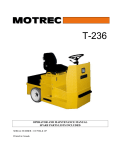
T-224D
OPERATOR AND MAINTENANCE MANUAL
SPARE PARTS LISTS INCLUDED
SERIAL NUMBER : 1039902 & UP
Printed in Canada
One Year Limited Warranty
Effective April 25, 2005, MOTREC, Inc. (MOTREC) hereby warrants to the Original Retail Purchaser (Owner) that any of its
vehicles shall be free from any defect in materials for a period of 90 DAYS while in the possession of such Original Retail
Purchaser. This warranty IS NOT TRANSFERABLE to any subsequent Buyer.
The warranty period is extended to one year or one thousand (1,000) hours, which ever first occurs, on the electric motor,
differential (parts that bathe in oil) and the electronic speed controller. MOTREC makes no warranty or representation with
respect to the internal combustion engine, tires and batteries, since their respective manufacturers cover such parts.
Accessories (light, gage, horn, etc), electrical contacts (switch, solenoid, contactor, relay), diodes & fuses, belts & pulleys,
filters & spark plugs, lubricants, brake linings & shoes, brake drums & discs, seals, seats, trim and other items subject to
wear are not included in this warranty; nor is any item that in MOTREC sole opinion, shows evidence of neglect, misuse,
abuse, collision or alteration.
This warranty shall not apply to normal maintenance requirements as described in the User Manual, and to damages during
shipment. The latter is the carrier's responsibility. No compensation will be allowed for delays.
To initiate warranty coverage on any MOTREC vehicle, the Dealer must complete and return the “Sales/Installation Report”
to MOTREC within 30 days after delivery to the Original Retail Purchaser; or within 90 days after the delivery date to the
Dealer, which ever occurs first. Failure to follow these procedures will result in considering the warranty coverage effective
as of the shipment date from the factory.
The defective vehicle must be returned, at the Owner's expense, to an authorised MOTREC Dealer within 30 days after
failure. The Owner will not be charged for parts and labour required for warranty repairs, which must be performed by an
authorised MOTREC Dealer only. The vehicle will be returned at the owner’s expense. The Warranty Claim Forms must be
completed and returned with the defective part(s) to MOTREC within 30 days after repair was done. No compensation will be
allowed for damages caused by vehicle downtime.
It is the responsibility of the owner of the vehicle to make sure that the driver is properly trained and instructed in the safety
features and operation of the vehicle, including vehicle stability, as required by OSHA and ANSI-B56. Operators shall read,
understand and follow the safety and operating instructions in MOTREC Manual before driving the vehicle. Operators shall
not be permitted to drive the vehicle unless a complete and adequate training has been provided. Driving a vehicle
constitutes a hazard. The driver is responsible for the control of the vehicle while driving and must always evaluate and care
for all peculiar situations that he or she may meet while driving. The driver assumes the inherent hazards related to this
activity. The vehicle is designed for off-road use only. MOTREC disclaims any liability for incidental or consequential
damages, to include, but not be limited to, personal injury or property damage arising from vehicle misuse, lack of
maintenance or any defect in the vehicle.
It is the responsibility of the Owner of the vehicle to make sure that the service technicians are properly trained as required
by OSHA and ANSI-B56. Service technicians shall read, understand and follow instructions in the MOTREC manual before
servicing the vehicle. Only qualified and authorized personnel shall be permitted to maintain, repair, adjust and inspect the
vehicle.
MOTREC prohibits, and disclaims responsibility for, any vehicle modification altering the weight distribution and stability,
increasing the speed or affecting the safety of the vehicle. Such modifications can cause serious personal injury or property
damage for which MOTREC disclaims any responsibility.
For Owners that are located outside North America, the warranty period starts the date of shipment from the factory, and the
defective parts must be returned at the Owner's expense to MOTREC prior to warranty repair.
24/04/2006
Table of contents
TABLE OF CONTENTS
INSTRUCTIONS
SAFETY WARNINGS FOR OPERATORS
MAINTENANCE
SAFETY WARNINGS FOR SERVICE TECHNICIANS
DECALS AND LABELS
PERIODIC MAINTENANCE CHECKLIST
BELT INSTALLATION AND TENSIONING
HYDRAULIC BRAKES
BATTERY MAINTENANCE
ELECTRICAL TROUBLESHOOTING
CURTIS SPEED CONTROLLER
WIRING : STANDARD CONFIGURATION
DIAGNOSTICS AND TROUBLESHOOTING
TROUBLESHOOTING CHART
LED DIAGNOSTICS
PROGRAMMING PARAMETERS –T-224/224D
SPARE PARTS
BODY
DIFFERENTIAL
BRAKE CONTRÔLS
STEERING WHEEL
MOTOR AND DRIVE
ELECTRICAL DIAGRAM – SEPEX MAIN CIRCUIT
ACCESSORIES – DC/DC CONVERTER
MOTREC ILLUSTRATED ACCESSORIES
CONVERTER INSTALLATION
BATTERY DISCHARGE INDICATOR (HOBBS)
ADDENDUM
CURTIS FOOT PEDAL
-3-
4
5
6
7
9
10
11
12
13
15
18
21
22
23
24
25
26
27
28
30
31
32
33
34
36
38
39
40
41
Instructions
INSTRUCTIONS
-4-
Instructions
SAFETY WARNINGS FOR OPERATORS
•
FAILURE TO OBEY THE FOLLOWING SAFETY RULES MAIN RESULT IN SEVERE INJURY.
•
It is the responsibility of the owner of this vehicle to train operators to ensure that they understand the operating
characteristics of this vehicle, including training in vehicle stability, and obey the following safety rules and
guidelines. Owner shall comply with OSHA and ASME/ANSI B56.8 & B56.9 regulations for vehicle use,
safety rules, operator training and certification. Do not drive this vehicle unless you are a qualified operator.
•
Do not drive this vehicle under the influence of drugs or alcohol.
•
Do not drive this vehicle on public roads and highways. This vehicle is designed to be driven in buildings.
•
The electrical system of this vehicle will make sparks which can ignite inflammable materials. Never use the
vehicle in hazardous areas where there are inflammable materials, explosive dust or fumes in the air.
•
Have your vehicle inspected regularly by trained personnel, and cease operation if a malfunction occurs.
•
Do not open battery compartment to prevent battery explosion, acid splashing, severe damage to eyes or skin.
•
Do not open motor compartment. Keep clear from moving, rotating(wheels, sheaves, etc) or lifting parts.
•
Never carry more passengers than number allowed for this vehicle. Wait until all occupants are seated and
holding on before moving. Always keep all body parts inside vehicle. Keep both hands on steering wheel.
•
Do not exceed the vehicle cargo load capacity and gross trailing weight capacity, rated for flat hard even surface.
Different operating conditions such as loose terrain or ramps reduce vehicle capacity.
•
Avoid loose, unbalanced or top-heavy loads to keep a good stability and prevent overturn. Do not load cargo that
can fall off the vehicle. Do not carry cargo that is longer, wider or higher than this vehicle.
•
Always depress slowly the accelerator for smooth acceleration. Avoid stunt driving or horseplay.
•
Avoid sharp turns, always slow down before turning, to prevent vehicle overturn or trailer jack knife. Vehicle is
more sensitive to overturn and jack knife when traveling on inclines or when carrying a heavy load.
•
Always drive straight up and down the face of an incline, never across the face, to prevent overturn and trailer
jack knife. Drive slower and start applying brakes sooner on inclines to adjust for longer stopping distance.
•
Use extra care and drive slowly in reverse, in congested areas or on wet or slippery ground.
•
Keep to the right under normal conditions. Maintain a safe distance from all objects.
•
Slow down and sound the horn when approaching a corner or other blind intersections.
•
Before leaving the vehicle, park on a level ground flat surface, turn off all switches, set the forward/reverse
switch to neutral, set the parking brake, remove the key. Do not park the vehicle on an incline.
•
Before battery charging, park the vehicle in a well ventilated area set for. Do not operate it when charging. To
interrupt a charging cycle, disconnect the AC plug; disconnecting the DC plug or a battery terminal, or operating
the vehicle, could damage the charger and produce a spark, battery explosion and acid splashing.
•
Use another driver to steer this vehicle while it is towed. Be sure the driver uses brakes when you slow or stop
the towing vehicle. Do not exceed 5 MPH or carry any passenger while towing this vehicle.
-5-
Maintenance
MAINTENANCE
-6-
Maintenance
SAFETY WARNINGS FOR SERVICE TECHNICIANS
FAILURE TO OBEY THE FOLLOWING SAFETY RULES MAIN RESULT IN SEVERE INJURY.
Owner shall comply with OSHA and ASME/ANSI B56.8 & B56.9 regulations for vehicle maintenance.
Only qualified and authorized personnel shall be permitted to maintain, repair, adjust and inspect
carriers, vehicles, tractors, and batteries.
Before any maintenance work, park the vehicle on flat level surface, turn off all switches, remove key,
lift wheels off the ground and secure with jack stands of adequate capacity. Don’t connect charger.
Keep clear from moving parts such as tires, sheaves and motor.
Follow the maintenance instructions applicable to the type of repair, maintenance, or service.
Always wear a face shield and gloves when working around batteries.
Before opening the battery compartment, disconnect the charger, turn off all switches and remove the
key. Batteries emit highly explosive gases which greatly increase when charging; do not disturb
connections or produce sparks around batteries to avoid a battery explosion and acid splashing. Battery
acid causes severe damage to eyes or skin. Flush contaminated area immediately with water.
Use insulated tools to avoid sparks that can cause battery explosion and acid splashing.
Use two counteracting tools, double-wrench technique, when disconnecting or tightening terminals on
the battery and the speed controller to avoid cracking the terminal or battery post welds.
Before cleaning or replacing a battery, charger, speed controller, contactor, relay, diode, or any other
component in the power circuit, always disconnect the charger, turn off all switches, remove the key,
wear a face shield and gloves, identify battery polarity and disconnect battery leads, discharge the
capacitor in the controller with a 10 ohms, 25 W resistor for a few seconds across B+ and B-.
After cleaning, the power must not be reapplied until terminal areas are thoroughly dry.
On EE-Rated vehicles make sure that the control box is sealed, the static strap makes good contact with
the ground, the motor is sealed by bands, the cable protectors are properly installed.
Keep cables and wires clear from mechanical and rubbing action. Make sure that cable insulation is
free from cutting or visible damage. Make sure that EE-Rated cable protectors are properly installed.
Before replacing a fuse or circuit breaker, identify the cause of failure and repair.
Programmable controllers must be programmed using the parameter settings in this service manual,
before connecting the motor, to avoid sudden vehicle movement and accident.
-7-
Maintenance
Do not try to increase motor speed by changing parameter settings in the speed controller; it can cause
accident and severe damage to the motor.
SEPEX speed controls are protected by a diode in the power circuit to filter inductive loads in the event
of a sudden power interrupt. Some speed controllers require a diode to filter inductive loads on the KSI
input. Removing the diodes will cause the speed control failure.
Before resuming maintenance operations, inspect safety warnings stickers and replace any if damage is
found and part of the text can’t be read.
-8-
Maintenance
DECALS AND LABELS
! CAUTION !
The images included in this section depict the decals/markings installed on the vehicle. It is of
the utmost importance that theses decals/markings remain unaltered and readable. Else, the
sticker or the part baring the marking has to be replaced.
Dashboard security warning label:
General security warning label:
Respectively, key switch markings, forward/reverse selector markings and light switch marking:
-9-
Maintenance
PERIODIC MAINTENANCE CHECKLIST
! WARNING !
Maintenance operations must be made by properly trained service technicians.
− Keep clear from moving parts such as tires, sheaves and motor.
− Check for all EE protections, when applicable, and keep cables and wires clear from mechanical and rubbing action
− Batteries contain sulphur acid that can cause severe burns on skin or eyes.
− When working around batteries, wear acid proof protective equipment: face shield and gloves.
− Use electrically insulated tools to avoid sparks that can cause battery explosion.
− Before any maintenance work, park the vehicle on a flat level surface, turn off all switches, remove the key, lift the wheels off the
ground and secure with jack stands of adequate capacity, identify and disconnect battery leads. Don’t connect the charger.
PERIOD DAY
CHECK/PERFORM
HOURS
MECHANICAL DAMAGE, OIL LEAKS
X
REVERSE ALARM, DEADMAN SWITCH
X
STATIC STRAP, min 2” contact with ground
X
TIRE PRESSURE, pressure rating on tire
CHECK/FILL BATTERIES, add distilled water to cover
plates. Fill to recommended level after batteries have
been fully charged.
WARNING DECALS & MARKINGS
EE-Rated CABLE PROTECTORS, SEALED MOTOR,
SEALED CONTROL BOX.
MASTER CYLINDER FLUID (DOT 3)
BRAKE PEDAL TRAVEL
2” (50 mm) maximum travel
STEERING FOR PLAY
PARKING BRAKE LEVER
requires 10 lbs. (5 kg) force to apply
BELTS AND PULLEYS
-10 lbs (5kg). force for 1/8” (3mm) deflexion;
-pulleys alignment, see procedure.
CLEAN/TIGHTEN WIRE TERMINALS
WASH BATTERY TOP WITH WATER
MOTOR BRUSHES FOR WEAR
-brushes must exceed holders
ACCELERATOR ADJUSTMENT
-1/8” (3 mm) travel to activate micro-switch;
-0 to 50 ohms when micro-switch activated;
-4500 to 5500 ohms with pedal down.
HYDR. BRAKE LINES FOR LEAK
STEERING ASSEMBLY, as instructed
BRAKE MECHANICAL LINKAGES
for wear & play
BRAKE LININGS FOR WEAR
1/16” (1.5 mm) minimum lining thickness.
LUBRICATE brake pedal pivots, steering column, ball
joints and kingpins.
OIL (SAE 30) LEVEL IN DIFFERENTIAL
Before adding oil, check oil seals for leaks.
FRONT WHEEL BEARINGS PLAY
TIGHTEN NUTS/BOLTS, electric terminals; drive;
steering; brakes; suspension; body.
WEEK
20
MONTH
50
QUART.
200
YEAR
1000
2 YEARS
2000
X
X
X
X
X
X
X
X
X
X
X
X
X
X
X
X
X
X
X
X
X
REPLACE DIFFERENTIAL OIL(SAE 30)
CLEAN AND RE-PACK FRONT HUBS
SERVICE DIFFERENTIAL, replace the three oil seals,
wheel bearings, oil (SAE 30)
X
X
X
- 10 -
Maintenance
BELT INSTALLATION AND TENSIONING
INSTALLATION
Adjust the sprockets using a straight edge. Slide up the edge on the larger pulley until it contacts the
smaller pulley. Properly adjusted pulleys will provide three points of contact. Properly aligned pulleys
will provide four points of contact. Tighten setscrews and recheck alignment.
TENSIONING
Check the force F required to provide a deflection of 1/8 in. If the measured force is less than 15 lbs
then lengthen centre distance C.
- 11 -
Maintenance
HYDRAULIC BRAKES
DRUM BRAKES
Remove brake drums and check linings wear; the linings should have a thickness exceeding 1/16" (1.5
mm). Turn the brake adjustment to reduce the clearance between lining and drum but avoid contact or
drag when the wheels are turned and the pedal is released.
DISC BRAKES
Check pad linings for excessive wear; the linings should have a thickness exceeding 1/16" (1.5 mm).
Disc brakes are self-adjusting.
BRAKE PEDAL
If the brake pedal becomes soft or spongy, air may have entered the hydraulic system and the brake
system has to be bled:
1. fill the master cylinder with brake fluid (DOT-3);
2. bleed front callipers one at a time by having someone applying a steady pressure on the brake
pedal, and close the bleeder before allowing the brake pedal to return to up position;
3. fill the master cylinder with brake fluid (DOT-3);
4. bleed rear wheel brakes one at a time, following the same procedure;
5. fill the master cylinder with brake fluid (DOT-3);
6. clean every fitting and line, remove traces of oil;
7. apply a continuous pressure on the brake pedal for about five minutes ;
8. Finally, inspect brake lines and fittings for leaks ;
- 12 -
Maintenance
BATTERY MAINTENANCE
−
−
−
−
−
−
−
−
−
−
! WARNING !
It is the responsibility of the owner of this vehicle to ensure that the service technicians are
properly trained, read and obey the safety rules and guidelines in this manual (ANSI B56).
Maintenance operations must be made by properly trained service technicians only.
Before any maintenance work, park the vehicle on a flat level surface, turn off all the
switches, set to neutral, remove the key, lift the wheels off the ground and secure with jack
stands of adequate capacity.
Keep charger disconnected while doing any maintenance work.
Always wear a face shield and scarf when working around batteries.
Battery emits highly explosive gases; do not produce sparks to avoid battery explosion and
acid splashing. Battery acid causes severe damage to eyes or skin. Flush contaminated area
immediately with water.
Use insulated tools to avoid sparks that can cause battery explosion and acid splashing.
Use two counteracting tools, double-wrench technique, when disconnecting or tightening
battery posts.
Before cleaning or replacing a battery, discharge the capacitor in the controller with a 10
ohms, 25 W resistor for a few seconds across B+ and B-, identify battery polarity and
disconnect battery leads.
After cleaning, the power must not be reapplied until terminal areas are thoroughly dry.
BATTERY LEADS AND CONNECTORS
Check for loose connections, damaged cables, acid spill, loose terminal posts, quarterly.
BATTERY POST CORROSION
If corrosion is present on battery posts, remove the cable connectors, use a wire brush to remove
particles, and then clean them with a cloth that has been moistened with ammonia.
ELECTROLYTE LEVEL
Does not apply to sealed battery.
− Disconnect battery connectors on roll-out or lift-out installations.
− Make sure the battery roll-out tray is provided with stops before rolling out.
− Fill with distilled water.
− Daily charged batteries normally require watering once a week. Under watering leads to a
shortened battery life. Over watering leads to battery corrosion. Be careful not to overfill any cell to
avoid electrolyte to be forced out while charging.
− Fill each cell to plate level with distillated or de-ionized water, before battery charging. When the
battery is charged, the fluid expands and can seep out if overfilled. Refill each cell after full charge,
when the fluid has expanded to its maximum level.
− Reinstall battery caps before charging.
- 13 -
Maintenance
BATTERY MOUNTING
A loose battery increases damaging effects of vibrations and is more prone to short out.
BATTERY DISCHARGE LIMIT
Discharging below a 20% state of charge cuts down the battery life and the number of cycles available.
At 20% state of charge, specific gravity of 6V battery should be 1180; and 1220 for industrial battery.
CHARGING AREA
− Always charge battery in a well ventilated area set for and approved for charging.
− Never leave a charger connected for more than 20 hours.
FREQUENCY OF CHARGE
− When a battery is discharged to its 20% state of charge, it is best to charge immediately.
− Batteries require a low current equalization charge (min 4 hours) at least every week, to equalize
battery cells, improve battery performance and life in number of cycles.
− Never leave a charger connected for more than 20 hours.
STORAGE
− Keep the battery from getting cold, it would loose its capacity.
− Let the battery warm up before charging.
− Charge batteries in “stored” vehicles every month.
DEFECTIVE BATTERY
Check specific gravity of each cell; if a cell is shorted, voltage drop may occur only when there is
current.
- 14 -
Maintenance
ELECTRICAL TROUBLESHOOTING
! WARNING !
Maintenance work must be performed by trained service technicians only.
It is the responsibility of the owner of this vehicle to ensure that the services technicians are properly
trained, understand and obey the safety rules and guidelines (ANSI B56).
All service technicians must read and understand the maintenance warning section in this manual.
! WARNING !
Before any maintenance work, park the vehicle on a flat level surface, turn off all switches, remove the
key, lift the wheels off the ground, secure with jack stands of adequate capacity, disconnect charger.
Always wear safety glasses.
Batteries emit highly explosive gases that can be ignited by a spark. Before disconnecting a high
current terminal, turn off all switches, disconnect battery charger, disconnect batteries.
Keep clear from moving parts such as tires, sheaves and motor.
PMC SELF DIAGNOSTIC
If your PMC comes with a status led, use the flashing code to help troubleshooting.
BATTERY VOLTAGE
Make sure batteries are securely connected. Measure voltage between + and - terminals. We will call
this value B+ or full battery voltage.
ACCESSORIES NOT WORKING
− Check the fuses on the batteries and the DC/DC converter.
− Check voltage across + and – terminals on the battery gage; if not B+, check wiring.
− Turn the key switch ON, check voltage between output terminal on the key switch and the terminal on the battery gage; if not B+, replace the key switch.
− Check voltage across DC/DC converter output terminals; if not 12-Volt, replace the converter.
− Depress the accessory switch, check voltage across accessory terminals. If not 12-Volt, replace the
switch. If 12-Volt, replace the accessory.
FORWARD ONLY
On a SEPEX motor control, check the reverse signal input on the controller.
On a series wound motor control, a bad reverse contactor is the most probable cause of the problem.
Switch to reverse and check voltage on the reverse control wire. If not B+, replace the F/R switch. If
B+, turn off the key switch, disconnect batteries, disconnect power terminals on the F/R contactors,
check the resistance across N.C. power terminals of the reverse contactor. If not 0 ohm, change the
reverse contactor. If 0 ohms, switch to forward and check the resistance across the forward N.O. power
terminals. If not 0 ohms, change the forward contactor.
- 15 -
Maintenance
REVERSE ONLY
On a SEPEX motor control, check the forward signal input on the controller.
On a series wound motor control, a bad forward contactor is the most probable cause of the problem.
Switch to forward and check the voltage on the forward control wire. If not B+, replace the F/R switch.
If B+, turn off the key switch, disconnect batteries, disconnect power terminals on the F/R contactors,
check the resistance across N.C. power terminals of the forward contactor. If not 0 ohm, change the
forward contactor. If 0 ohms, switch to reverse and check the resistance across the reverse N.O. power
terminals. If not 0 ohms, change the reverse contactor.
TRAVEL AT REDUCED SPEED
Check batteries.
Turn off all switches and disconnect charger. Wear face shield and gloves. Do not disturb any
battery connection to avoid sparks. Check the specific gravity of each cell. Cold batteries,
highly discharged batteries or dead cells are the most frequent causes of reduced travel speed.
Check potentiometer.
Turn off the key switch, disconnect potentiometer terminals. Check the resistance between
terminals.
Other causes of lower speed:
− dragging brakes;
− cold temperature (higher differential oil viscosity).
INTERMITTENT OPERATION
A bad potentiometer is the most probable cause of the following:
− acceleration is not constant;
− maximum speed is erratic;
− sudden stop after a bump or shock;
− erratic starts, requiring several pedal cycles.
A bad F/R contactor is also a probable cause of the following:
− sudden stop after a bump or shock;
− would not start to move at times.
Erratic starts could also be the cause of a misadjusted potentiometer or micro-switch; the pot signal
must be less than 50 ohms when the micro-switch turns on.
PMC has an HPD safety feature that prevents the vehicle from moving if the accelerator pedal is
depressed before the key switch is ON and seat switch is activated.
PMC may also have an SRO safety feature that prevents the vehicle from moving if the F/R switch is
activated before turning on the key switch and activating the seat switch.
The vehicle stops on a steep and long ramp or while towing a heavy load: the circuit breaker has open
to prevent motor overheating and will reset automatically after one minute. The PMC is also equipped
with an internal thermal protection that cutback the current until the PMC has cooled down.
- 16 -
Maintenance
NO MOTION
Make sure that the PMC surface is clean and dry; check the terminal areas. Dust Particles or acid
contamination, can create current leaks and cause a PMC malfunction.
Check F/R switch
Turn on the key switch and set to forward. Check voltage between the forward terminal and the
– terminal on the battery gage, check voltage between the reverse terminal and the – terminal on
the battery gage; if both B+, replace the F/R switch.
Check switches and wiring
Disconnect control terminals on the PMC and check all control signals. If a switch pin does not
read B+, check wiring or replace the switch.
Check potentiometer
Turn the key switch to OFF, disconnect potentiometer terminals. Check the resistance across
terminals: if not within the recommended limits, adjust or replace the potentiometer. Check for
shorts between potentiometer wires and vehicle frame; resistance should read at least 1
megohm.
Check main contactor or solenoid
Check voltage across power terminals; if not B+, check circuit breaker or replace the solenoid.
Turn to on the key switch and activate the seat switch. Check voltage across the coil terminals;
if not B+, check wiring and interlock switches. Check resistance across power terminals; if not
0 ohms, replace the solenoid.
Check circuit breaker and SEPEX DIODE
Before replacing the circuit breaker, check for shorts in the power circuit and check the SEPEX
diode in the power circuit using a diode tester. If no such instrument is at hand, use an
ohmmeter: the reading should be weak in one direction and strong in the other way.
Check the resistance across the circuit breaker. If not 0 ohms, replace the circuit breaker.
Check PMC
First disconnect battery B+ and B-, then PMC B+ and M-. Check the internal diode between B+
and M- terminals using a diode tester. If no such instrument is at hand, use an ohmmeter: the
reading should be weak in one direction and strong in the other way. If the internal diode is
defective, the PMC must be replaced.
Check the Motor
First disconnect battery B+ and B-, disconnect power terminals and check the motor armature
and field for opens.
- 17 -
Curtis Speed Controller
CURTIS SPEED CONTROLLER
- 18 -
MODEL
MANUAL
12 4 4
MultiMode™
MOTOR CONTROLLER
© 2001 CURTIS INSTRUMENTS, INC.
DESIGN OF CURTIS PMC 1200 SERIES
CONTROLLERS PROTECTED BY U.S.
PATENT NO. 4626750.
CURTIS PMC
235 East Airway Boulevard
Livermore, California 94568 USA
Tel: 925-961-1088
Fax: 925-961-1099
www.curtisinst.com
1244 Manual, p/n 16958
Rev. B: January 2001
- 19 -
1244 Manual
p/n 16958, Rev. B: January 2001
© 2001 CURTIS INSTRUMENTS, INC.
CURTIS INSTRUMENTS, INC.
200 KISCO AVENUE
MOUNT KISCO, NEW YORK 10549 USA
☎ 914-666-2971 FAX 914-666-2188
CURTIS PMC
235 EAST AIRWAY BOULEVARD
LIVERMORE, CALIFORNIA 94550 USA
☎ 925-961-1088 FAX 925-961-1099
ADDITIONAL OFFICES located in
Bulgaria, China, England, France, Germany,
India, Italy, Japan, Netherlands, Puerto
Rico, Russia, Sweden, and Switzerland
www.curtisinst.com
- 20 -
2 — INSTALLATION & WIRING: Controller
WIRING: Standard Configuration
Figure 3 shows the typical wiring configuration for most applications. The
interlock switch is typically a seat switch, tiller switch, or foot switch.
Standard Power Wiring
Motor armature winding is straightforward, with the armature’s A1 connection
going to the controller’s B+ bus bar and the armature’s A2 connection going to
the controller’s M- bus bar.
The motor’s field connections (F1 and F2) to the controller are less obvious.
The direction of vehicle travel with the forward direction selected will depend on
MAIN
CONTACTOR
COIL
FORWARD
REVERSE
5 kΩ–0 THROTTLE
(TYPICAL)
MODE SELECT 2
MODE SELECT 1
INTERLOCK
B-
F1
M-
B+
F2
KEYSWITCH
MAIN
CONTACTOR
A
B-
A2
A1
F1
F2
POWER
FUSE
POLARITY
PROTECTION
DIODE
CONTROL
FUSE
B+
Fig. 3 Standard wiring configuration, Curtis PMC 1244 controller.
Curtis PMC 1244 Manual
- 21 -
8
8 — DIAGNOSTICS & TROUBLESHOOTING
8
DIAGNOSTICS AND TROUBLESHOOTING
The 1244 controller provides diagnostics information to assist technicians in
troubleshooting drive system problems. The diagnostics information can be
obtained by observing the appropriate display on the handheld programmer, the
fault codes issued by the Status LED, or the fault display driven by the controller’s
Fault 1 and Fault 2 outputs. Refer to the troubleshooting chart (Table 5) for
suggestions covering a wide range of possible faults.
PROGRAMMER DIAGNOSTICS
The programmer presents complete diagnostic information in plain language.
Faults are displayed in the Diagnostic Menu (see column 2 in the troubleshooting
chart), and the status of the controller inputs/outputs is displayed in the Test
Menu.
Accessing the Diagnostic History Menu provides a list of the faults that have
occurred since the diagnostic history file was last cleared. Checking (and clearing)
the diagnostic history file is recommended each time the vehicle is brought in for
maintenance.
The following 4-step process is recommended for diagnosing and troubleshooting an inoperative vehicle: (1) visually inspect the vehicle for obvious
problems; (2) diagnose the problem, using the programmer; (3) test the circuitry
with the programmer; and (4) correct the problem. Repeat the last three steps as
necessary until the vehicle is operational.
Example: A vehicle that does not operate in “forward” is brought in
for repair.
STEP 1:
Examine the vehicle and its wiring for any obvious problems,
such as broken wires or loose connections.
2: Connect the programmer, select the Diagnostics Menu, and
read the displayed fault information. In this example, the display
shows “No Known Faults,” indicating that the controller has not
detected anything out of the norm.
STEP
STEP 3:
Select the Test Menu, and observe the status of the inputs and
outputs in the forward direction. In this example, the display shows
that the forward switch did not close when “forward” was selected,
which means the problem is either in the forward switch or the switch
wiring.
STEP 4:
Check or replace the forward switch and wiring and repeat the
test. If the programmer shows the forward switch closing and the
vehicle now drives normally, the problem has been corrected.
Curtis PMC 1244 Manual
- 22 -
77
8— DIAGNOSTICS & TROUBLESHOOTING
Table 5 TROUBLESHOOTING CHART
LED
CODE
1,2
PROGRAMMER
LCD DISPLAY
FAULT
CATEGORY
EXPLANATION
POSSIBLE CAUSE
HW FA I L SA FE 1 - 2 - 3
1
self-test or watchdog fault
1. Controller defective.
M - SHOR TED
1
internal M- short to B-
1. Controller defective.
F I E L D OPEN
1
field winding fault
1. Motor field wiring loose.
2. Motor field winding open.
ARM S ENSOR
1
armature current sensor fault
1. Controller defective.
F L D S ENSOR
1
field current sensor fault
1. Controller defective.
THROT T L E FAU L T 1
1
wiper signal out of range
1. Throttle input wire open.
2. Throttle input wire shorted to B+ or B-.
THROT T L E FAU L T 2
1
pot low fault
1. Throttle pot defective.
2. Wrong throttle type selected.
2,2
SRO
3
SRO fault
1. Improper sequence of KSI, interlock, and
direction inputs.
2. Wrong SRO type selected.
3. Interlock or direction switch circuit open.
4. Sequencing delay too short.
2,3
HPD
3
HPD fault
1.
2.
3.
4.
2,4
B B W I R I NG CHECK
1
emergency reverse wiring fault
1. Emergency reverse wire open.
2. Emergency reverse check wire open.
3,1
CON T DRVR OC
1
cont. driver output overcurrent
1. Contactor coil shorted.
3,2
MA I N CONT WE L DED
1
welded main contactor
1. Main contactor stuck closed.
2. Main contactor driver shorted.
3,3
PREC HARGE F AU L T
1
internal voltage too low at startup
1. Controller defective.
2. External short, or leakage path to B- on
external B+ connection.
1,3
2,1
Improper seq. of direction and throttle inputs.
Wrong HPD type selected.
Misadjusted throttle pot.
Sequencing delay too short.
M I S S I NG CON TACTOR
1
missing contactor
1. Any contactor coil open or not connected.
3,4
MA I N CONT DNC
1
main contactor did not close
1. Main contactor missing or wire to coil open.
4,1
LOW B A T TERY VOL TAGE
2
low battery voltage
1. Battery voltage <undervoltage cutback limit.
2. Corroded battery terminal.
3. Loose battery or controller terminal.
4,2
OVERVOL TAGE
2
overvoltage
1. Battery voltage >overvoltage shutdown limit.
2. Vehicle operating with charger attached.
3. Battery disconnected during regen braking.
4,3
THERMA L CUT BACK
2
over-/under-temp. cutback
1.
2.
3.
4.
4,4
ANT I - T I EDOWN
3
Mode 2 or Mode 4 selected at
startup
1. Mode switches shorted to B+.
2. Mode switches “tied down” to select Mode 2
or Mode 4 permanently.
Curtis PMC 1244 Manual
- 23 -
Temperature >85°C or < -25°C.
Excessive load on vehicle.
Improper mounting of controller.
Operation in extreme environments.
78
8 — DIAGNOSTICS & TROUBLESHOOTING
LED DIAGNOSTICS
A Status LED is built into the 1244 controller. It is visible through a window in
the label on top of the controller. This Status LED displays fault codes when there
is a problem with the controller or with the inputs to the controller. During normal
operation, with no faults present, the Status LED flashes steadily on and off. If the
controller detects a fault, a 2-digit fault identification code is flashed continuously
until the fault is corrected. For example, code “3,2”—welded main contactor—
appears as:
¤ ¤ ¤
¤ ¤
(3,2)
¤ ¤ ¤
¤ ¤
(3,2)
¤ ¤ ¤
¤ ¤
(3,2)
The codes are listed in Table 6.
Table 6 STATUS LED FAULT CODES
LED CODES
LED off
solid on
0,1
1,1
1,2
1,3
1,4
2,1
2,2
2,3
2,4
3,1
3,2
3,3
3,4
4,1
4,2
4,3
4,4
EXPLANATION
no power or defective controller
controller or microprocessor fault
¤
¤ ¤
¤ ¤¤
¤ ¤¤¤
¤ ¤¤¤¤
¤¤ ¤
¤¤ ¤¤
¤¤ ¤¤¤
¤¤ ¤¤¤¤
¤¤¤ ¤
¤¤¤ ¤¤
¤¤¤ ¤¤¤
¤¤¤ ¤¤¤¤
¤¤¤¤ ¤
¤¤¤¤ ¤¤
¤¤¤¤ ¤¤¤
¤¤¤¤ ¤¤¤¤
■
controller operational; no faults
[not used]
hardware failsafe fault
M-, current sensor, or motor fault
[not used]
throttle fault
static return to off (SRO) fault
high pedal disable (HPD) fault
emergency reverse circuit check fault
contactor driver overcurrent
welded main contactor
precharge fault
missing contactor, or main cont. did not close
low battery voltage
overvoltage
thermal cutback, due to over/under temp.
anti-tiedown fault
NOTE: Only one fault is indicated at a time, and faults are not queued up. Refer
to the troubleshooting chart (Table 5) for suggestions about possible causes of the
various faults.
Curtis PMC 1244 Manual
- 24 -
79
Curtis Speed Controller
PROGRAMMING PARAMETERS –T-224/224D
! WARNING !
The owner of this vehicle shall ensure that the service technicians are qualified, properly trained and obey
the safety rules and guidelines in OSHA and ANSI B56 regulations, and in this manual.
Before installing and/or programming the PMC, park the vehicle on a flat level surface, lift the wheels off
the ground and secure with jack stands of adequate capacity. Don’t connect charger.
Programmable controllers must be programmed using the parameter settings in this service manual, before
connecting the motor, to avoid sudden vehicle movement and accident.
Do not try to increase motor speed by changing parameter settings in the speed controller; it can cause
accident and severe damage to the motor.
VOLTAGE
NOMINAL BATTERY VOLTAGE, IN VOLTS
2
THRO. DEADBAND
Thr. Neutral deadband % of 5kohms pot
6
M1 DRIVE C/L
MODE 1 DRIVE CURRENT LIMIT, IN AMPS
300
THROTTLE MAX
Thr. Input req`d for 100%PWM %5kohm pot
90
M2 DRIVE C/L
MODE 2 DRIVE CURRENT LIMIT, IN AMPS
300
M1 THRTL MAP
MODE 1 THROTTLE MAP, AS %
30
M3 DRIVE C/L
MODE 3 DRIVE CURRENT LIMIT, IN AMPS
300
M2 THRTL MAP
MODE 2 THROTTLE MAP, AS %
30
M4 DRIVE C/L
MODE 4 DRIVE CURRENT LIMIT, IN AMPS
300
M3 THRTL MAP
MODE 3 THROTTLE MAP, AS %
30
M1 BRAKE C/L
MODE 1 BRAKING CURRENT LIMIT, IN AMPS
150
M4 THRTL MAP
MODE 4 THROTTLE MAP, AS %
30
M2 BRAKE C/L
MODE 2 BRAKING CURRENT LIMIT, IN AMPS
150
FIELD MIN
MIN. FIELD CURRENT, IN AMPS
7.5
M3 BRAKE C/L
MODE 3 BRAKING CURRENT LIMIT, IN AMPS
150
FIELD MAX
MAX. FIELD CURRENT, IN AMPS
30
M4 BRAKE C/L
MODE 4 BRAKING CURRENT LIMIT, IN AMPS
150
FIELD MAP START
Armature current at wich FIELD MAP takes effect, amps
150
50
M1 THRT BRK %
MODE 1 THROT. BRAKING, AS % OF BRAKE C/L
50
FIELD MAP
Field Winding Current, as % of Armature Current
M2 THRT BRK %
MODE 2 THROT. BRAKING, AS % OF BRAKE C/L
50
CURRENT RATIO
CURRENT RATIO:FACTOR OF 1, 2, 4 OR 8
1
M3 THRT BRK %
MODE 3 THROT. BRAKING, AS % OF BRAKE C/L
50
RESTRAINT
RAMP RESTRAINT: 1 TO 10
3
M4 THRT BRK %
MODE 4 THROT. BRAKING, AS % OF BRAKE C/L
50
LOAD COMP
LOAD COMPENSATION: 0 TO 25
0
M1 ACCEL RATE
MODE 1 ACCELERATION RATE, IN SEC.
4
HPD
HIGH PEDAL DISABLE (HPD) TYPE
1
M2 ACCEL RATE
MODE 2 ACCELERATION RATE, IN SEC.
4
SRO
STATIC RETURN TO OFF (SRO) TYPE
1
M3 ACCEL RATE
MODE 3 ACCELERATION RATE, IN SEC.
4
SEQUENCING DLY
SEQUENCING DELAY, IN SEC.
M4 ACCEL RATE
MODE 4 ACCELERATION RATE, IN SEC.
4
MAIN CONT INTR
MAIN CONTACTOR INTERLOCK: ON OR OFF
DECEL RATE
DECELERATION RATE, IN SEC.
M1 BRAKE RATE
MODE 1 BRAKING RATE, IN SEC.
2.5
1
ON
MAIN OPEN DELAY
MAIN CONTACTOR DROPOUT DELAY, IN SEC.
1
3
WELD CHECK
MAIN CONTACTOR WELD CHECK: ON OR OFF
ON
M2 BRAKE RATE
MODE 2 BRAKING RATE, IN SEC.
3
MAIN CHECK
MAIN COIL OPEN CHECK: ON OR OFF
ON
M3 BRAKE RATE
MODE 3 BRAKING RATE, IN SEC.
3
AUX ENABLE
AUXILIARY ENABLE: ON OR OFF
OFF
M4 BRAKE RATE
MODE 4 BRAKING RATE, IN SEC.
3
EM BRAKE
ELECTROMAGNETIC BRAKE ON OR OFF
OFF
QUICK START
QUICK START THROTTLE FACTOR
4
AUX DELAY
AUXILIARY DRIVER DROPOUT DELAY, IN SEC.
TAPER RATE
Regen brak. Decrease rate when apporch. 0spd,
1/32s
32
AUX CHECK
AUXILIARY COIL OPEN CHECK: ON OR OFF
OFF
M1 MAX SPEED
MODE 1 MAX. SPEED, AS % PWM OUTPUT
40
EM BRAKE DELAY
ELECTROMAGNETIC BRAKE DELAY, IN SEC.
0
M2 MAX SPEED
MODE 2 MAX. SPEED, AS % PWM OUTPUT
100
EM BRAKE CHECK
ELECTROMAG. BRAKE OPEN CHECK: ON OR OFF
OFF
M3 MAX SPEED
MODE 3 MAX. SPEED, AS % PWM OUTPUT
40
REV DRVR CHECK
REVERSE SIGNAL OPEN CHECK: ON OR OFF
OFF
M4 MAX SPEED
MODE 4 MAX. SPEED, AS % PWM OUTPUT
40
CONT PULL IN
CONTACTOR COIL PULL-IN VOLTAGE, AS %
100
M1 CREEP SPEED
MODE 1 CREEP SPEED, AS % PWM OUTPUT
0
CONT HOLDING
CONTACTOR HOLDING VOLTAGE, AS %
100
M2 CREEP SPEED
MODE 2 CREEP SPEED, AS % PWM OUTPUT
0
EMR REV ENABLE
EMERGENCY REVERSE FUNCTION : ON OR OFF
OFF
0
M3 CREEP SPEED
MODE 3 CREEP SPEED, AS % PWM OUTPUT
0
EMR REV C/L
EMERGENCY REVERSE CURRENT LIMIT, IN AMPS
M4 CREEP SPEED
MODE 4 CREEP SPEED, AS % PWM OUTPUT
0
EMR REC CHECK
EMERGENCY REV. WIRING CHECK : ON OR OFF
OFF
50
REGEN SPEED
Min. speed for regen braking, as % of vehicle speed
25
ANTI-TIEDOWN
ANTI-TIEDOWN: ON OR OFF
OFF
CTRL MODE
CONTROL MODE
1
FAULT CODE
ON OR OFF
ON
THROTTLE TYPE
THROTTLE TYPE
3
PEDAL INTERLOCK
THREADLE, PB-6, CHECK WIRING
OFF
PRECHARGE
ON OR OFF
ON
#REF:
1244-0510401
- 25 -
Spare Parts
SPARE PARTS
- 26 -
Spare Parts
BODY
REF. NUMERO
1
2
3
4
5
6
7
8
6105236001
2355236001
2356236001
2200010
2311000006
283001
2807001
2807007
2450001
900-2595
2200018
2662002
2500250002
2205002
DESCRIPTION
BODY
ROLLER
SHAFT, ROLLER
BEARING
RUBBER BUMPER 16”
4.8X8 LRC WHEEL
BLACK SOFT RUBBER WHEEL
RIB GREY SOFT RUBBER WHEEL
STATIC STRAP
FLOOR MAT, ADHESIVE
PIN, ROLL-OUT
SPRING, PIN ROLL-OUT
DASHBOARD
GRAMMER SEAT WITH SWITCH
- 27 -
Spare Parts
DIFFERENTIAL
- 28 -
Spare Parts
REF.
PART NO
DESCRIPTION
1
2
3
4
5
481433
2173236001
242053
242054
481430K
481431K
481430RK
2420011
2420010
242058
242059
2113000002
2122236001
242060
242061
2235008
2320006
242063
242064
242065
242066
242067
242069
242070
242071
242072
242073
242074
3620027
242076
3620006
242078
DISC (HYDRAULIC BRAKE)
REAR AXLE
LOCK
WHEEL STUD
LEFT CALIPER
RIGHT CALIPER
REPAIRE KIT, CALIPER
OIL SEAL
NEEDLE BEARING
NUT
FLAT WASHER
PULLEY W90
MOUNTING PLATE (CALIPER)
OIL SEAL
TAPERED BEARING
HOUSING
SPACER
BREATHER
SPACER
TAPERED BEARING
SHIM
GEAR KIT
SHIM
TAPERED BEARING
CASE
WASHER
GEAR KIT
WASHER
GEAR KIT
SCREW
SHAFT
CAP
BOLT
DRAIN PLUG
DIFFERENTIAL COVER
BOLT
BRAKE HOSE FOR DISC BRAKE
BRAKE PADS
BOLT, LONG
BOLT, SHORT
HYDRAULIC BOLT
WASHER
BUSHING, LONG
BUSHING, SHORT
8
9
12
13
14
15
16
17
18
19
20
21
22
23
24
27
28
29
30
31
32
33
34
35
36
37
38
39
42
43
44
45
46
47
48
242079
242080
2420019
481432
2814003
481434
481442
481440
481441
3614002
3614003
- 29 -
Spare Parts
BRAKE CONTRÔLS
RÉF. PARTS NO. DESCRIPTION
QTY.
RÉF. PARTS NO.
DESCRIPTION
QTY.
1
2
3
4
5
6
7
8
1
1
2
1
2
1
1
1
9
10
11
12
13
14
15
16
HANDBRAKE
YOKE
CABLE
HANDBRAKE PAD
HANDBRAKEPAD
CLIP
SPRING
CABLE STOPPER
1
1
1
1
1
1
1
1
242801
2131248001
2132248002
2190000003
122813
2133300001
2125000001
2135248001
RUBBER
BRAKE LEVER
PIVOT
SPRING
YOKE 3/8
ROD
MASTER CYLINDER
SUPPORT
- 30 -
3616013
2416009
362831A
2316005
3616014
362832
3616015
362833
Spare Parts
STEERING WHEEL
RÉF.
PART NO.
DESCRIPTION
RÉF.
PART NO.
DESCRIPTION
1
2
3
4
5
6
7
8
9
10
11
12
13
14
15
16
2330014
2330013
2230014-HBK
2200224004
2330015
2230015
2230016
2230017
2200224003
2809000001
2200248002
2200224002
231404
2330012
2110248001
2205248001
HORN BUTTON
STEERING WHEEL
HORN BRUSH KIT
TILT/TEL COLUMN
UNIVERSAL JOINT
SUPPORT
WASHER
BUSHING
SHAFT
RUBBER BOOTS
NYLON COUPLER
SHAFT
UNIVERSAL JOINT
PIVOT
CHAIN 46”
FRONT PIVOT
17
18
19
20
21
22
23
24
25
26
27
28
29
30
31
2110248002
2203248001
2102124001
201434
2229300002
2103300003
2224300002
2103300005
2910300002
2229300001
2230023
366221
2361001
366212
800TXA
CHAIN 40 1/2”
FORK
BEARING
WASHER
OIL SEAL
BEARING
HUB
BEARING
JAM NUT 1 1/4 - NF
DUST CAP
CASE F/R
GREY HANDLE
NAMEPLATE F/R
SWITCH
CONTACT BLOC
- 31 -
Spare Parts
MOTOR AND DRIVE
COMMON PARTS
REF
DESCRIPTION
1
2
3
4
5
6
PULLEY
V BELT
PULLEY
BELT, EAGLE
MOTOR BASE, GM
BELT TENSIONER, LONG
BELT TENSIONER, SHORT
7 PIVOT
PART #
RE DESCRIPTION
F
262424
242431
3651001
3651002
Contact manuf.
2452005
2452003
2452002
PART #
8 MOTOR BASE, FORD
BELT TENSIONER
9 SEAL
10 BEARING
11 SNAP RING
12 NUT WASHER PACK
15 WAVY WASHER
19 HEADBAND
EE HEADBAND KIT
Contact manuf.
2152002
484001
484003
484004
484006
484013
484015
A91-107A
SPECIFIC
REF
13
14
16
17
18
DESCRIPTION
MOTOR ASS’Y
BRUSH SPRING
BRUSH PLATE
LEAD ASSY.
BRUSH
LEAD AND BRUSH ASSY.
A89
B98
A00
484000
484010
484011
484017
484009
N/A
204050
484010
484011
484017
484009
N/A
2950002
2450006
2450007
N/A
N/A
2450008
- 32 -
D00 SEPEX
2450003
2450006
2450007
N/A
N/A
2450008
DC3 SEPEX
3112210001
2450006
2450007
N/A
N/A
3112210004
DANA DRIVE
3122230001
2450006
2450007
N/A
N/A
2450008
Spare Parts
ELECTRICAL DIAGRAM – SEPEX MAIN CIRCUIT
DIAGRAMME ÉLECTRIQUE – CIRCUIT PRINCIPAL SEPEX
- 33 -
Spare Parts
ACCESSORIES – DC/DC CONVERTER
ACCESSOIRES – CONVERTISSEUR DC/DC
- 34 -
Spare Parts
PARTS LIST
NO
DESIGNATION
REF
QTY
A2
B1
B2
B3
E1
F1.A,B
F3
F5
G1
M2
M10
P1
R1
SEPEX SPEED CONTROL
STROBELIGHT
HORN
REVERSE ALARM
HEADLIGHT
FUSE, 15A
CIRCUIT BREAKER, 150A
DIODE BRIDGE
BATTERY
SEPEX MOTOR
COOLING FAN – 12V
HOUR METER, BATTERY GAUGE
ACCELERATOR CURTIS
POTENTIOMETER
SPRING
MICRO-SWITCH
LEVER
KEY SWITCH
SEAT SWITCH, MICRO-SWITCH
SEAT SWITCH, SEAT MOUNTED
F/R SELECTOR - TILT/TEL COLUMN
LIGHT SWITCH, ROCKER TYPE
HORN BUTTON, TILT/TEL COLUMN
HYDRAULIC BRAKE LIGHT SWITCH
EMERGENCY PUSH BUTTON
EMERGENCY PUSH BUTTON, LABEL
DC-DC CONVERTER
HOUR METER CONNECTOR
SPEED CONTROL CONNECTOR
MAIN CONTACTOR
HEAVY DUTY MAIN CONTACTOR
STATIC STRAP
1244-4451
*
*
*
*
246108K
3107000002
3669027
1
1
1
1
1
2
1
1
S1
S3
S7
S8
S10
S12
S15
U1
X1
X2
Y1
* Consult Motrec illustrated parts
- 35 -
3129224001
*
3062001C
367008
2262004C
2262001C
2262003C
246205
3109100002
366216
366212
1269004
*
3669004
3109800001
3109800006
*
1
1
1
1
1
1
1
1
1
1
1
1
1
1
1
1
1
246112
1
GE800AH205X0 1
2450001
1
Spare Parts
MOTREC ILLUSTRATED ACCESSORIES
Strobelight, polemount
Amber 12-80V: 3116000001
Red 12-80V:
2469001
Blue 12-80V:
3690008
Red Tail/Brake light
Housing:
3069012R
Bulb 12V:
3117240001
Headlight
Left:
Right:
Bulb H/L:
Bulb Turn:
Bulb Mark:
3111480003
3111480004
3117480001
3117480003
3117480002
Horn button VIP
2330014
Horn button, column mount
246210
Strobelight, cab mount
Amber 12-48V: 3116250001
Red 12-48V:
3069026
Blue 12-48V:
3069014
Amber 72-80V:3116720001
Red 72-80V: 3116720002
Blue 72-80V: 3116720003
Back-up lamp
Grommet:
12V:
24V:
Turn signal switch
246050
3269001
3669012
3669012A
Horn button, dash mount
266210
Clear lamp
12V:
Bulb 12V:
3069012
1269008
Analog Voltmeter
12V :
3069007
24V :
2469002
36-48V :
3669002
Horn button
3109250001
Amber turn lamp
12V:
3069020
Bulb 12V:
3069021
Pedestral head lamp
12V:
2569001
Bulb 12V:
2569001B
Bulb 24V:
4469001
Red Tail/Brake light
Grommet:
3269001
Plug:
246012A
12V :
2469021
24V :
2469022
Red Tail/Brake light
12V:
386002
Headlight
Left:
Right:
Bulb H/L:
Bulb Turn:
Bulb Mark:
3111480003
3111480004
3111480006
3111480008
3111480007
Limit switch
HOBBS Gauge
24V:
36V:
48V:
3030015
2469026
3069038
4869037
Back-up alarm
12-48V :
3100000001
72-80V :
3105720001
Horn
12V:
24V:
- 36 -
246003
246013
Spare Parts
Wiper arm
2800000001
DC-DC converter, 10A
12-48V:
3069019
DC-DC Converter, 25A
12-48V:
3124000002
72-80V:
3124880001
Wiper blade
14” Blade:
18” Blade:
Cab heater
12V:
36V:
48V:
3103300001
3669008
4869020
2800000002
2800000003
12V Dome light
Wiper motor
12V:
24V:
3113000001
486211
Headlamp 12V:3111250002
3669006
Headlamp
12V:
Bulb 12V:
3111300001
3111300002
Pantograph wiper arm
246233A
12V Fan
Pantograph wiper blade
246233
- 37 -
3669013
Red Pilot light
12V:
Bulb 12V:
246212
246212B
Spare Parts
CONVERTER INSTALLATION
- 38 -
Spare Parts
BATTERY DISCHARGE INDICATOR (HOBBS)
This indicator monitors :
− the residual capacity of batteries;
− operating hours;
− status of service down counter.
The residual capacity of the battery is monitored via an 8-LED bar display. When the left red LED
lights, the batteries must be charged to avoid damage. The LED display starts flashing as a pre-warning
signal. The lower voltage limit is adjustable via potentiometer “M” on the rear.
A
1,57
B
1,63
C
1,68
D
1,73
E
1,78
F
1,82
G
1,84
H
1,86
I
1,89
J
1,91
K
1,93
In order to activate a new adjustment, the unit has to be reset :
− 2.35V/cell reset voltage with battery remaining in vehicle;
− 2,09V/cell reset voltage after battery has been disconnected.
To maintain a good battery performance, it is recommended to limit the discharging to 80% of the
battery capacity. The recommended setting for 6V batteries is F and the recommended setting for an
industrial battery is K.
An internal relay can prevent overdischarging and damaging the batteries. The relay can be wired to
cut off the reverse direction, or energize an N.C. relay and alarm.
Turning off and on the vehicle will override the protection for 30 sec.
The current status (remaining operating hours before maintenance) of the service down counter is
indicated for a period of 5 seconds after the key switch is turned on. When it is down to 0, the display
flashes. After the maintenance, reset the counter: depress the button “R” on the rear. The service
counter is factory programmable only.
24V UNIT #: 2469026
36V UNIT #: 3069038
48V UNIT #: 4869037
2- Orange, key switch
3- Relay +
4- Relay 5- Black, battery –
6- Blue, hour counter
8- White, battery +
- 39 -
Addendum
ADDENDUM
- 40 -
Addendum
CURTIS FOOT PEDAL
RESP :
NO :
CLAUDE L
235A224001
PART. NO
DESCRIPTION
3062001C
367008
2262004C
2262001C
2262003C
3662002
ACCELERATOR CURTIS
POTENTIOMETER
SPRING
MICRO-SWITCH
LEVER
CABLE PROTECTOR
MODEL(E) :
SER :
- 41 -
T-224/236/248
TO/À :