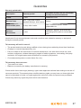
1
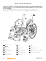
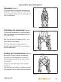
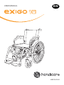
USER MANUAL
EN
MB3195-EN-B
Introduction
Congratulations on your choice of new wheelchair.
Quality and functionality are keywords for all Handicare wheelchairs.
Legend 2 Exigo is manufactured by Handicare.
For your own safety, and in order to get the greatest benefit from the features
of your new wheelchair, we recommend that you read this user manual carefully
before you start to use the wheelchair.
About Handicare Exigo 10
Exigo 10 has been developed in collaboration with the market. The result is a
unique wheelchair that is very comfortable and has good rolling characteristics.
A total width only 18 cm greater than the seat width provides good accessibility
through narrow doors and in tight spaces.
Exigo 10 is easy to transport in a car or in other vehicles; the chair is only 30 cm
wide when folded.
Intended use
Exigo 10 is designed for both indoor and outdoor use. This wheelchair has
been developed for persons with disabilities and as an aid for those who have
problems with walking. Users who can control the wheelchair by rolling, steering
and braking it themselves can use the wheelchair without an assistant.
Adjusting the wheelchair
All adjustments mentioned in this User manual are to be performed by qualified
personnel or in consultation with qualified personnel.
www.handicare.com
2
MB3195-GB
Contents
Introduction...................................................................................2
Contents ........................................................................................3
Parts of the wheelchair ................................................................4
Assembly and transport...............................................................5
Using the wheelchair....................................................................6
Fitting a positioning belt ............................................................14
Safety ...........................................................................................15
Safety in cars ..............................................................................16
Maintenance ...............................................................................19
Technical specifications ............................................................23
Labelling ......................................................................................24
Guarantee....................................................................................26
MB3195-GB
3
Parts of the wheelchair
In order to be able to read and understand this manual it is important that you familiarise yourself with the most common terms that we use for the different parts
of the wheelchair.
Have a look at figure 1 and note the relevant parts on your wheelchair.
The equipment on your wheelchair may vary slightly from the figure shown.
8
1
2
3
9
4
11
10 12
5
6
13
7
14
Figure 1
1
Backrest with backrest
cover
2
3
4
5
Armrests
4
Seat
6
7
8
9
Leg support
10 Hand rim
Clothing guards
Frame
11 Brake
Footplate
12 Wheel block
Pushing handle
13 Front castor wheel fork
Driving wheels
14 Front castor wheel
MB3195-GB
Assembly and transport
Assembly Figure 2
The wheelchair is supplied complete as
standard. The only thing you need to do
is to unfold the chair and, if necessary, fit
the leg supports.
Figure 2
Unfolding the wheelchair Figure 3
Unfold the wheelchair by pushing down
with flat hands on the upholstery next to
the seat tubing.
NB: Do not grasp the seat tubing – you
may catch your fingers!
Put the seat cushion (accessory) in
position and ensure that it lies correctly
on the seat fabric.
Figure 3
Folding up the wheelchair Figure 4
Remove the seat cushion (accessory)
and fold up the footplates or remove
the leg supports before you fold up the
wheelchair.
Grasp the seat fabric and lift it directly
upwards.
The seat will fold itself up. Make sure that
the backrest fabric folds itself backwards.
Figure 4
MB3195-GB
5
Using the wheelchair
Quick-release hub Figure 5
The wheelchair has a quick-release hub
on each of the driving wheels. Depress the
button in the centre of the driving wheel to
remove or replace the wheel.
NB: Check that the wheel is properly
fastened by making sure that the button
pops out about 5 mm when the wheel bolt
is fully in the casing.
Figure 5
Armrests, swing-up Figure 6
• Press the release button and pull up the
armrest
Ensure that the armrest
locks into position
when you swing
it back down.
Figure 6
6
MB3195-GB
Using the wheelchair
Swinging out/fitting/removing
the leg supports Figures 7
The leg supports can be swung in and
out or removed to make transfers easier.
The leg support is released by turning the
handle (7A) inwards or outwards while
swinging the leg support.
Once the leg support has been swung to
the side, it can be lifted up and removed
completely if desired. To replace it, follow
the above procedure in the reverse order.
The handle will automatically lock itself.
MB3195-GB
A
Figure 7
7
Using the wheelchair
Using the brakes Figure 8
Pull the brake lever towards you to lock
the brake.
The brakes are only designed to
keep the chair stationary. Under no
circumstances must they be used as
a driving brake.
Figure 8
Anti-tip stabiliser Figure 9
The anti-tip stabiliser is deployed by
pulling it out while simultaneously turning
it down.
The anti-tip stabiliser is adjusted as
standard with a clearance to the floor
which makes it possible to negotiate door
sills and similar.
Figure 9
8
MB3195-GB
Using the wheelchair
Transferring into and
out of the chair
Figures 10, 11 and 12
• Engage the brakes
• Swing the leg supports out if necessary
• Move yourself to the front of the chair
before transferring to another chair,
bed, etc.
Figure 10
Figure 11
Figure 12
MB3195-GB
9
Using the wheelchair
Negotiating obstacles: steps
Figures 13 and 14
If the wheelchair is to be lifted up or down
steps with the user in the chair, if possible
use the recommended lifting points.
The lifting points are the pushing handles
and leg supports.
Figure 13
In order for the assistants to have a better
lifting position, they may lift one on each
side of the chair.
Negotiating obstacles:
kerbstones Figure 15
When negotiating kerbstones or similar,
swing up the anti-tip stabiliser. Then
place a foot on the tipping bar while you
simultaneously push with the pushing
handles.
Figure 14
Steep ground
If you frequently use the wheelchair on
hilly surfaces, we recommend that a
separate assistant brake be installed.
Figure 15
10
MB3195-GB
Adjusting the wheelchair
Adjusting the height of the back
of the seat Figure 16
You can adjust the height of the back
of the seat using any of the methods
described below.
Move the wheel up or down
If you move the wheel up, you lower the
seat height. If you move the wheel down,
you raise the seat height.
Change to larger or smaller driving wheels
Using larger driving wheels raises the seat
height, whereas smaller driving wheels
lower the seat height.
Figure 16
Adjusting the height of the back
of the seat Figure 17
The height of the back of the seat can be
raised or lowered by moving the wheel up
or down in the frame.
• Undo the screws (17A)
• Move the wheel up if you wish to lower
the seat height
A
• Move the wheel down if you wish to
raise the seat height
• Retighten the screws
MB3195-GB
Figure 17
11
Adjusting the wheelchair
Adjusting the height of the front
of the seat Figure 18
You can adjust the height of the front
of the seat using any of the methods
described below.
Front castor
wheel fork
A
Move the front castor wheel to a higher or
lower position in the castor fork
By moving the castor wheel to a higher
position in the castor fork (18A) you lower
the seat height; by moving the castor
wheel to a lower position you raise the
seat height.
Front castor
wheel
Figure 18
• Undo the screw in the hub of the castor wheel fork
• Move the wheel up or down
• Retighten the screw
Change to larger or smaller castor wheels
Using a smaller castor wheel lowers the seat height, whereas a larger castor
wheel will raise the seat height. If you change the castor wheels to a smaller
model, this will reduce the turning circle and thereby make it easier to negotiate
tight spaces. It will also provide more room for your legs. On the other hand,
using larger castor wheels will increase the turning circle but will make it easier to
negotiate uneven surfaces.
12
MB3195-GB
Adjusting the wheelchair
Adjusting the brakes Figure 19
To move the brakes, undo the screw
(19A) located on the inside of the frame
at the front of the chair. Move the entire
brake assembly along the track to the
desired position. The correct distance
between the brake block and the wheel
is about 2.5 cm.
It should not normally be necessary to
adjust the brakes from the position in
which they are delivered.
A
Figure 19
Adjusting the anti-tip stabiliser
Figure 20
You should adjust the anti-tip stabiliser
when you have changed the centre of
gravity of the chair.
• Undo the screws (20A). Push or pull
the anti-tip stabiliser to the correct
position
A
• There should be a maximum of 25 mm
from the end of the anti-tip stabiliser to
the floor
• Retighten the screws
Figure 20
Adjusting the length of the leg
supports Figure 21
To adjust the length of the leg-rest,
unscrew the screws (21A), adjust
to the desired length, then replace the
screws and tighten.
A
Figure 21
MB3195-GB
13
Fitting a positioning belt
Fitting the hip belt (accessory)
Figures 22, 23 and 24
• Unscrew the screw (22A). Use a 4 mm
Allen key.
A
• Fit the hip belt as shown in figure 23.
Use the screw you removed.
• Check that the hip belt is correctly
adapted to the wheelchair user. The
belt should lie firmly over the hip at an
angle of approx. 45° from the fixing
position on the wheelchair.
• Make sure the belt is clean and that the
locking mechanism works at all times.
The belt and locking mechanism can
be cleaned using a damp cloth.
Figure 22
Placing the belt over the hip, against
the soft skin of the stomach, can result
in the wrong sitting position and the user
sliding forward in the wheelchair.
Figure 23
Correct placing of belt
Incorrect placing of belt
45˚
Figure 24
14
MB3195-GB
Safety
• Do not stand on or exert great pressure on the footplates.
• A wheelchair should be considered as a replacement for walking. Users must
therefore move among pedestrians and not on trafficked roadways.
• When you wish to transfer out of the chair, ensure that you are on as stable
and even a surface as possible. In order to ensure that the chair does not
move, make sure that the brake is in the locked position.
• Exigo 10 must not be used as a passenger seat in a vehicle. The wheelchair
user must be transferred to the vehicle’s passenger seat and must use the
vehicle’s safety belt.
• The maximum weight capacity for Exigo 10 is 140 kg.
• You should regularly inspect the chair to reassure yourself that all screws,
bolts and other fastenings are secure.
• When the chair is in use, always ensure that the anti-tip stabiliser is activated.
• When any modifications are made to the chair, such as moving the drive
wheels, moving the front castor wheels, changing the backrest height, etc.,
this will affect the chair’s rolling characteristics, balance and tipping point.
Therefore, be particularly careful when starting to use the chair again.
• It is recommended that a qualified helper be used when transferring into and
out of the chair.
• Ensure that clothing, bags and other items do not get caught in the wheel
spokes.
• Be aware of the danger of possible trapping injuries: avoid putting your fingers
between the clothing guard and the wheel, and between the wheel and the
brake.
• If while using the chair it is necessary to raise the front of the chair in order to
negotiate an obstruction, never do this by just pressing down on the pushing
handles. Tread on the tipping bar while exerting moderate pressure on the
pushing handles.
• Sitting in a wheelchair for a long period of time increases the danger of
pressure sores. If there is a high risk of pressure sores, we recommend the use
of special seat cushions to counteract the problem.
• The surface temperatures can increase when the wheelchair is exposed to
external sources of heat (e.g. sunlight).
MB3195-GB
15
Safety in cars
Exigo 10 as a passenger seat in a car
Wheelchair users should transfer to the vehicle seat and use the vehiclemanufacturer-installed restraint systems whenever it is feasible, and the
unoccupied wheelchair should be stored in a cargo area or secured in the vehicle
during travel.
The wheelchair can be used as a passenger seat in a car and has been tested in
accordance with ISO 7671-19.
When the wheelchair is used as a passenger seat it should be facing forward.
The wheelchair must be attached to the fastening system it was tested for;
The system is a 4-point fastening system. The system is a total system that
fastens both the wheelchair and user to the car. The system requires fastening
rails to be mounted in the car.
User restraint system: 3 point shoulder and hip belt.
Exigo 10 has marked off four points (Figure 25) that must be used when securing
the wheelchair:
• The rear tubing of the side frame, above the wheel block.
• The front tubing of the side frame, above the legrest hanger.
Figure 25
Handicare relinquishes itself of all responsibility in the event that Exigo
10 is used as a passenger seat in a car using a different fastening system to
the one mentioned above.
16
MB3195-GB
Safety in cars
Fastening the seat belt:
• The pelvic-belt restraint must be
fastened at as steep an angle as
possible; between 30° and 75°
• The shoulder-belt restraint is fastened
over the shoulder and chest
• The seat belt is fastened as tightly to
the body as possible and must not be
twisted
• Make sure the belt restraints is not kept
away from the body by the wheelchair
parts, such as armrests and wheels.
For correct positioning, see figure
below
• The chair must not be tilted backwards
when used as a passenger seat
in a car
Figure 26
Make sure that the seat
belt is not kept away from
the body by the wheelchair
parts, such as armrests and
wheels.
WARNING
a) Where possible, the wheelchair should be in a forward facing
direction and secured in accordance with the instructions from
the manufacturer of the fastening system.
b) This wheelchair is approved for use in cars and meets the
requirements for forward facing transport and head on collisions.
The wheelchair has not been tested for other positions in a
vehicle.
c) The wheelchair has been dynamically tested in a forward facing
direction, with the user secured by both a stomach and chest
belt (3-point seat belt)
MB3195-GB
17
Safety in cars
d) Both the stomach and chest belts should be used to reduce the
risk of head and chest injuries in the event of colliding with parts
in the car.
e) In order to reduce the risk of injury to the user, tables that are
fitted to the wheelchair, which are not designed for crash safety,
must be:
• Removed and secured separately in the vehicle, or
• Secured to the wheelchair, but with energy-absorbing padding
placed between the table and the user
f) Where possible, other wheelchair accessories should be secured
to the wheelchair or removed from the chair and secured in the
vehicle during transport, so that they don’t become loose and
cause injury to the user in the event of a collision.
g) Support and positioning equipment must not be regarded as
safety equipment/seat belts if they are not labelled in accordance
with the requirements of ISO 7176-19-2008.
h) The wheelchair should be inspected by a representative of the
manufacturer before being used again after any kind of collision.
i) No changes or replacements must be made to the anchorage
points/car fastenings on the wheelchair, or to constructional
elements or parts of the frame without consulting the
manufacturer.
j) When using electric wheelchairs in motor vehicles, gel-filled
batteries should be used.
18
MB3195-GB
Maintenance
Maintenance described in this section can be carried out by the user. Other
maintenance work should be carried out by qualified personnel at the
supplier in your municipality or at the technical aids centre. For information
about repairs or servicing, please contact the technical aids centre in your
county.
Washing the frame
The frame should be washed regularly with warm soapy water. If the frame is
very dirty, a degreasing agent may be used. The frame may be washed with
a high-pressure hose. If you use this method, avoid directly spraying the ball
bearings. Dry the wheelchair well after washing it or after it has been used in
rainy conditions. If a degreasing agent is used, moving parts should be greased
afterwards.
Disinfection
Disinfection must only be carried out by qualified personnel. The wheelchair
can be disinfected with disinfectants that contain 70-80% ethanol. Do not use
disinfectants containing chlorine or phenol.
Cleaning the seat and backrest covers
The upholstery and backrest cover can be washed in a washing machine at
60 °C. See the washing instructions on the various textiles.
Conditions which could damage the wheelchair
The chair should not be used at temperatures below -35 °C or over 60 °C. No
specific requirements are made in connection with humidity or air pressure. No
further requirements are made regarding storage conditions.
MB3195-GB
19
Maintenance
Screws and nuts
Screws and nuts can become loose over time. Therefore, remember to check
and if necessary retighten all screws and nuts on a regular basis. A threadlocking product, such as Loctite Blue No. 243, may be used.
If self-locking nuts have been removed they lose some of their locking ability and
should be replaced.
Driving wheels
The driving wheels are fitted with spokes. These should be checked and adjusted
at least once a year. Contact a local bicycle dealership or your nearest technical
aids centre.
Quick-release hub for wheels
The quick-release hub for the driving wheels requires regular inspection. Check
that the ball bearings are working satisfactorily. The release bolt and ball bearings
should be cleaned and oiled regularly.
20
MB3195-GB
Maintenance
Recommended pressure
The chair is supplied as standard with solid wheels.
Find the indication of the size on the driving wheel or castor wheel, and then read
off the recommended maximum pressure in the table. Note that a high pressure
makes the chair easier to roll, whereas a low pressure gives a smoother ride.
For optimal rolling characteristics, the pressure should be checked regularly.
kPa
Bar
PSI
Driving wheel, pneumatic
350
3.5
50
Driving wheel, high-pressure
630
6.3
90
Front castor wheel, 6", pneumatic
250
2.5
35
Front castor wheel, 8", pneumatic
250
2.5
35
Inspection after six months, thereafter each year
• Check that the brakes function correctly. Adjust if necessary.
• Check that the tyres are in good condition and that there has been no damage
to the sidewalls.
• Ensure that the chair is clean and that all moving parts function correctly.
• Check for any slack in the front castor wheel forks, and adjust if necessary (i.e.
the axle should run freely around its axis, but there should be no slack up or
down).
• Check and if necessary adjust all screwed connections.
Repairs
Apart from small repairs to paintwork, the replacement of tyres and inner tubes,
and the adjustment of the brakes, all repairs must be undertaken by qualified
personnel at the supplier in your municipality or at the technical aids centre.
For information about repairs or servicing, contact the technical aids centre in
your county.
MB3195-GB
21
Maintenance
Replacing pneumatic tyres
B
Figure 27
Pneumatic tyres are an accessory
Removing the tyre
• Remove the wheel, then deflate the
tyre by depressing the little pin in the
valve or unscrewing the valve.
• Ensure that the edge of the tyre sits
well down in the internal depression of
the wheel rim (27A).
• Bend the edge of the tyre over the
rim. Use a special tyre lever (27B) if
necessary. Take care to ensure that
the tube does not become pinched
between the lever and the rim.
C
A
Figure 27
Fitting the tyre
• Put the tube into the new tyre and
apply a friction-reducing agent (tyrefitting lubricant or soap) on the edge
of the tyre (27C).
• Ensure that the edge of the tyre sits
well down in the depression of the
wheel rim on one side. Bend the
tyre over the rim edge. Take care to
ensure that the tube does not become
pinched.
• Inflate to the correct pressure and fit
the wheel to the chair.
22
MB3195-GB
Technical specifications
Technical specifications and measurements
The wheelchair is supplied as standard in various different seat heights and seat
widths. Which height suits the user of the wheelchair depends on two factors:
the height of the individual and how the chair will be used. Consult your dealer
or nearest technical aids centre if you are uncertain whether you have the correct
height and width. (All measurements are in centimetres unless stated otherwise.)
Seat width
39, 42, 45, 48 and 51 cm
Seat depth
40, 46 cm
Seat height
45, 47 and 49,5 cm
Backrest height
40, 43 cm
Armrest height
24 cm
Total height
90 cm
Total width
Seat width + 18 cm
Transport width
30 cm
Total length
100 cm
Weight of chair
17,5 kg
Max. user weight
140 kg
The wheelchair and most of the parts are manufactured using a special
aluminium alloy. The backrest and seat are covered with flame-retardant material.
The driving and caster wheels can be supplied with solid or pneumatic tyres as
desired.
Under normal use and with prescribed maintenance, the wheelchair’s expected
lifespan is approximately seven years.
Waste handling
Waste relating to packaging, parts of the wheelchair or the wheelchair itself
can be treated as general waste. The main component of the wheelchair is
aluminium, which can be melted down for reuse. The plastic and cardboard used
in the packaging can be recycled.
MB3195-GB
23
Labelling
Product name
CE mark
Seat width
Seat depth
Max. user weight
Climbing angle
Anchorage points car
Year and month
of production
Serial number
24
MB3195-GB
Accessories
•
•
•
•
•
•
Amputation blocks
Assistant brake
Front castor wheels
Leg support, adjustable-angle
Backrest, Velcro
Table
Fitting instructions are supplied with
accessories.
Contact your nearest Handicare branch
for accessories and spare parts.
MB3195-GB
25
Guarantee
Warranty
Definitions of terms
Definitions of terms used in this warranty:
• Consumable part: Part that is subjected to natural wear and tear or natural contamination during
normal operation within the lifetime of the product (section 9 of Handicare’s general terms and
conditions of sale);
• Client: Those who purchase the product directly from Handicare;
• Corrective action: Repair, replace or refund of the product;
• Dealer: Those who re-sell the product to the User;
• Defect: Any circumstance due to which the product is not sound or fit to use, caused by a lack of
quality of the material used to manufacture the product as well as the quality of the manufacturing
process;
• Option: An accessory delivered by Handicare to extend the standard product model;
• Product: Product that is delivered according to brochure or contract (e.g. wheelchair, scooter,
battery-charger etc.);
• Part: Part of product that can be exchanged or replaced. This can be an option, accessory,
service part or consumable part;
• Returns: Product or part that needs to be returned;
• RMA-process: Process to return goods, contact your dealer;
• Service part: Part that is durable and may be subjected to natural wear and tear or natural
contamination during normal operation within the lifetime of the product.;
• User: Those who use the product;
• Warranty: The rights and obligations set forth in this document;
• Warranty period: The period of time during which the warranty is valid;
• Warranty provider: Handicare B.V., Vossenbeemd 104, 5705 CL Helmond, The Netherlands.
Notwithstanding the rights and obligations of Handicare, Client and User set forth in Handicare’s
general terms and conditions of sale, the rights of the Client and/or User towards Handicare in case
of defects are limited to the provisions set forth in this warranty. For the duration of the warranty
period Handicare guarantees that the product is without defects.
In case of any defects the User is required –within two weeks after discovery of the defect- to
contact the dealer. He has to complete a return form and return the product or part via the RMAprocess. Handicare will, at its sole discretion, take the corrective action it seems fit under the given
circumstances within a reasonable period of time (depends on nature of claim) from receipt of the
completed return form. The warranty period will not be extended after a corrective action.
26
MB3195-GB
Guarantee
Warranty period table
Description
Warranty period
Examples include, but are not limited
to the parts mentioned below
Frame
5 years
Weldment/frame
Service Parts
New: 1 year after invoice
Repaired: 90 days after invoice
Brakes
Consumable parts
40 days after invoice
Seat- and back textiles, wheels,
griphandles etc.
2 years
Headrests, legrests, drum brake etc.
Not being service part or consumable
part.
Options/
Accessories
Handicare will only accept shipment costs and corrective costs related to warranty on equipment
during the warranty period.
This warranty will void in case of:
• The product and/or its parts being modified or items having been added by others than Handicare;
•
•
•
Changes in cosmetic appearance by use;
Failure to observe the instructions for use and maintenance, use other than normal use, wear
and tear, negligence, collateral damage by neglect of earlier symptoms, overloading, third-party
accidents, non-original parts used and defects not caused by the product;
Circumstances beyond our control (flood, fire, etc.).
This warranty does not cover:
•
•
Tyres and inner tubes
Batteries (covered by the battery manufacturer’s warranty).
Clients and/or Users have legal (statutory) rights under applicable national laws relating to the sale of
consumer products. This warranty does not affect statutory rights you may have nor those rights that
cannot be excluded or limited, nor rights against the entity from whom the product was purchased.
Clients may assert any rights they have at their sole discretion.
MB3195-GB
27
Notes
28
MB3195-GB
Notes
MB3195-GB
29
Notes
30
MB3195-GB
Notes
Warning: The content of this user manual is only intended as information. This information may
be changed without warning and must not therefore be interpreted as an obligation on the part of
Handicare. Handicare is not responsible, either legally or financially, for any errors or inaccuracies
that may appear in this user manual. All products that are mentioned in this user manual are
registered trademarks and cannot be used in other contexts without the consent of Handicare.
MB3195-GB
31
Dealer:
Serial number: