1
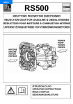
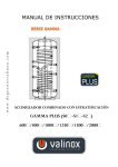
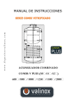
CL-1500
Copy Lathe
210651
User Manual
W
Axminster Reference No: CL-1500
w w w. a x m i n s t e r. c o . u k
AXMINSTER
W H I T E
Copying Wood Turning Lathe
Content
1 General notices – use of machine
2 packing list
3 Information on the copying wood lathe
3.1 Use of the product
3.2 Technical description
3.3 Technical characteristic
3.4 Circuit diagram
3.5 List of the purchasing parts
4 Information and requirement on the working place
5 Requirement on transport, storage and mounting
5.1 Unpacking, cleaning
5.2 Erection, mounting
6 Information on operating personnel
7 Information on operating of the lathe
7.1 Operating
7.2 Starting
7.3 Turning off
7.4 Emergency switching-off
7.5 Starting after emergency switching-off
7.6 Adjusting and controlling
7.7 Danger, safety measures
7.8 Failures and their elimination
7.9 Operation notices
7.10 Basic features of the tools
7.11 Regulations for reduction of noise and vibration
8 Regulations for maintenance and servicing
8.1 Maintenance
8.2 Inspection
8.3 Repair
9. Appendix
2
Copying Wood Turning Lathe
GENERAL NOTICES
Dear Customers,
In order to use your new copying wood lathe with its full values and without problem, it is
necessary to follow the following suggestions:
- When getting the machine, the completeness of the parts should be checked/see the part list /;
- After unpacking, the single parts should be checked for transport damage;
- Before erecting and starting of the machine, this user’s manual should be read in detail.
We hope you have a successful work with the copying wood lathe.
1 USE OF THE MACHINE
1.1 Regulation of the machine
The machine facilitates the turning work of the semi-finished products of wood and wood base.
The machine is designed for operation only by one worker.
Any manipulation for children and youngster is forbidden.
1.2 Qualification of the worker
Only the specialist trained in wood processing or the worker who is instructed and taught by this
specialist is allowed to work on the machine without consideration of sexual distinction. For the
work on the machine, the operator is obliged to know this manual and to abide by all the safety
regulations, arrangements and regulations which are valid in concerned countries.
1.3 Working surrounding
The machine must work in the workshop surroundings which temperature doesn’t surpass +40℃
and doesn’t fall under +5℃. The relative air humidity in the range of 30% to 95% - not
condensing. The elevation up to 1000m. Surrounding classification – fire danger of the flammable
dust.
3
Copying Wood Turning Lathe
2 PACKING LIST
No.
Name
Quantity
1. Copying wood lathe
1
2. Copying device
1
3. Tailstock
1
4. Pan
1
STANDARD ACCESSORY
6. BucketФ40
1
7. Bow
8. Faceplate
1
9. Turning tip MT2
1
10. Front-tip MT2
1
11. Arbor for three-jaw chuck 16
1
12. Three-jaw chuck 16
1
13. Steady rest
1
TOOLS AND ACCESSORIES
14. Special Spanner
1
15. Pin
1
SPECIAL ACCESSORIES
16. Universal flange
1
3 INFORMATION ON THE COPYING WOOD LATHE
3.1 Use of the product
The copying wood lathe is a wood processing machine, which is suitable for roughing turning and
finish turning of wood products.
The machine is driven by an electric motor. The machine can operate under production conditions
as well as under household conditions. The turning according to the pre-made template or the
pre-made model is made possible by the copying device.
3.2 Technical description
The copying wood lathe consists of the following important elements and parts /Fig.1, Fig.2/:
body /1/-the headstock/3/ and the guide – round –Ф50 and rectangular – 80 x 60 are mounted in
the body /1/.
The copying device /4/ is mounted on the both guides. The copying wood lathe is fixed to the
foundation by body /1/ and support /6/. The latter are equipped with four holes Ф13 for the
foundation bolts.
The spindle /13/ is carried on the headstock on the bearings /11/ and /12/. The electric motor is
fixed under the headstock by two consoles /15/ and /16/, what make the belt tensioning possible.
The two 4-stage pulleys /17/ and /18/ are mounted on the shaft of the electric motor and on the
spindle, so that the rotation movement is transferred. The spindle rotation speeds are displayed on
the front panel of the machine according to the belt setting -/7/.
The pulleys /17/ and /18/ and the belt /19/ are ensured by a door /2/.
The lathe can not work, if the door is opened. One limit switch guarantees that the door is closed.
The tool support /9/ can be fixed on the guides of the copying wood lathe, and the copying device
4
Copying Wood Turning Lathe
/3/ is displaced in advance. The displacement takes place to the right till the limit position. One
pan /8/ for tool and raw piece is mounted on the lathe. The electric installation of the copying
wood lathe consists of: electric panel, control desk, motor, circuit breaker and cable. The principle
circuit diagram of the lathe is shown on page.
Copying device – Fig.6, 7, 8, 9
The copying device is fixed on the guides by body /34/. It is driven by the nylon-box /36/ onto the
cylindrical guide/quill and is driven by the two roller bearings /32/ onto the rectangular guide .
The longitudinal movement happens by means of gear and gear rack through handle /37/.
The copying is carried out by a tool which is fixed on the tool holder /56/ with two screws M8 x
10. The tool holder is mounted onto the plunger /29/ through two bushings /60/ and /61/ and screw
M8 x 35 and is ensured against rotation by means of the feather key /59/.
The plunger makes its movement in the quill /28/ over the bronze-box /31/ and is fixed in the nut
of the quill through the feather key against rotation. It is necessary to make regular lubrication of
the bushings by means of the pressure grease gun /35/. The plunger is pressed by spring /30/ in the
top position. The plunger stroke is 50mm. The spring is adjusted by nut /27/. The bow /41/ is fixed
on the low end of the plunger through bushings /39/ and /40/ and screw M8 x 35. The plate /52/
which connects the plunger to the lever is attached on the bow.
The quill /28/ is mounted in the body of the copying device and has possibility to reach the fixable
stroke of 45mm. The quill is fixed through screw /46/. The bow /57/ is fixed on the low end of the
quill through the two bushings /54/ and /55/ and screw M8 x 40. The cross-feed of the tool is
adjusted with screw M14 x 2 /45/. The finger is made in two variant /50/ and /53/, depending on
the maximal size of the curve of the wood template or metal template. The finger has an adjusting
possibilities of 32mm through the plate /51/. The round template is mounted between the tips /49/
which are fixed on the two consoles /48/. The tips are mounted onto the console /47/ through
screws M6 x 20 and the console is fixed on the rectangular guide at the side. The consoles have an
adjustment range of 50mm.
The plane template is mounted directly onto the consoles /48/ through screw M8. The stroke of the
plunge is carried out by the means of the lever /44/ manually. The fixing of the lever upward is
carried out through the adjustment screw /45/. This adjustment screw is limited by the console /42/
which is fixed on the lever. The cross-copying routine is 1200mm, and when rotating the handle
clockwise, the copying device moves to the front tip. For one revolution, the copying device is
shifted for 113mm. The cross copying range is 50mm, and a fixed feed is made possible through
screw /48/. For one revolution of the screw, a cross-feed of the tool of 1mm happens.
The copying device is used for cross-copying according to round template and plane template, and
also for copying according to original piece.
5
Copying Wood Turning Lathe
3.3 Technical characteristic
No.
Parameter
Size unit
1.
Max. processing length
mm
2.
Max. length for cross-copying
mm
3.
4.
5.
6.
7.
Max. diameter for cross-copying
Copying depth
Distance-guide-spindle shaft
Distance-ground-turning shaft
Spindle rotation speed
mm
mm
mm
mm
rpm
8.
Outside measurement:
- width
- height
- length
mm
mm
mm
9.
Weight
kg
10.
Installed power
kW
value
1250 (CL1300)
1450 (CL1500)
1100 (CL1300)
1300 (CL1500)
120
50
210
1030
500
1000
1950
2800
480
1150
2000 (CL1300)
2200 (CL1500)
218 (CL1300)
228 (CL1500)
1.1
3.4 Circuit diagram
3.4.1 Electric connection(Three-phase motor)
The copying wood lathe is driven by a three-phase motor.
The power supply connection happens by means of a three-pin 16A plug to be prepared by user.
ATTENTION: The power supplying of the copying wood lathe happens by means of a three-phase
switchboard with a 10A fuse.
3.4.2 Technique of the electric safety
The following protection and locking devices are planed in the copying wood lathe:
- Overload protection – bimetallic thermally-operated relay F1;
- Minimal voltage protection – K1M – Protection switch
- Locking device – when the protection cover is removed, the electric motor will not start
- Micro-circuit-breaker S4. All the electric devices are connected to the protection line of the
power supply through an earthing rail.
Its earthing happens after mounting of the machine, and the earthing screw is connected to the
earthing circuit of the room.
The keys “EIN”(S2) and “AUS”(S3) are used for turning on and turning off of the copying wood
lathe. In case of accident the machine is to turn off through the key “NOT-AUS”(S1).
ATTENTION: All the repair works on the electric circuit of the machine must be carried out
absolutely under the condition that the machine is unplugged.
6
Copying Wood Turning Lathe
Three-phase
Single-phase
LIST OF THE ELEMENTS OF THE ELECTRIC CIRCUIT OF THE COPYING WOOD
LATHE
Name
Specification
Quantity
in electric circuit
piece
Protection
K1M
1
Thermoelectric relay
F1
1
Circuit breaker
S4
1
Key “Stop”
S3
1
Key “Start”
S2
1
Emergency-stop switch
S1
1
Electric motor
M
1
3.5 List of the purchasing parts
No.
Name
Specification
Basic parameter
Piece
1.
belt
1250O/10x6
1
2.
bearing
6208ZZ
40x80x18
1
3.
bearing
6206ZZ
30x62x16
1
4.
bearing
6000 2RS
10x26x8
5
5.
bearing
6202 2RS
15x35x11
2
6.
part of electric circuit
according to
P.3.5
4 INFORMATION AND REQUIREMENTS ON THE WORKING PLACE
The copying wood lathe can work in any room with an air temperature over 5℃ and a relative air
humidity of max. 75%.
The foundation is carried out on concrete ground without special requirements /see P.5.3/.
During operation of the copying wood lathe, wood cuttings are cut off and accumulated near the
machine. In order to guarantee their exhaustion during the operation, a way to connect with a local
exhaustion equipment is planned. The connection happens through a matching part which is
equipped with an output pipe of diameter 100mm, which is mounted on the body of the copying
device.
The machine has no influence upon the environment.
7
Copying Wood Turning Lathe
5 REQUIREMENT ON MOUNTING
5.1 Unpacking
Disposal of reserving material
After the copying wood lathe is unpacked, the reserving material is to dispose of. For this purpose,
all the areas must be cleaned with threads which are a little soaked with mineral turpentine or gas
oil.
5.2 Erection, mounting
5.2.1 Foundation
The machine is mounted on a plane ground. 4 holes are marked on the ground according to the
holes of the body /1/ and the support /6/ respectively – Fig.1. The lathe is shifted to the side and 8
holes are drilled on the footing. The diameter depends on the type of footing - /with dowels or
foundation bolts/. After checking the level, the body /1/ and support /6/ are locked to the ground.
5.2.2 Trial operation of the machine
After foundation and connection of the power supply, the copying wood lathe is tested in idle
running to check if the spindle shows the correct rotation direction / seen anti-clockwise opposite
the spindle /. The belt tensioning (if necessary) and the change of the rotation speed are carried out
in the following order:
- Open the door /2/ - Fig.1, in which the handle is turned.
- Unscrew lightly screws /23/ and /24/ through hexagonal box spanner 8 – Fig.2.
- Draw out the handle /26/ and lift motor lightly till engagement with the cross-slot of the plate
/25/ on screw /23/.
- Adjust the belt to the required position.
- Draw out the screw /23/ from the cross-slot of the plate /25/ by lifting with the handle /26/ and
the belt under the motor cover is tensioned.
- Screw on screws /23/ and /24/.
- Close the door /2/ - Fig.1.
Note: The turning on of the copying wood lathe with the door opened is blocked by a circuit
breaker.
5.2.3 Adjustment of the machine for operation with different accessories
The following parts are used as accessories:
a/ Turning tip- it is fixed in the quill of the tailstock.
b/ Faceplate – it is used for face turning of unsymmetrical parts.
c/ Changeable front tip – it is used for the operation with the faceplate for centering of raw piece.
d/ Steady rest – it is attached to the guides and is used for turning of parts with small diameter and
big length.
e/ Universal chuck P16 – it is fixed on the tailstock through a special arbor.
5.2.4 Operation preparation of the copying device
- The play between guide and roller bearing must be checked. If necessary, adjust it through the
plate /33/.
- Check the movement of the copying device completely – it must be light and free of failure.
- The plunger running in the whole range and the lever system for driving the plunger must be
checked.
- Adjust quill /26/, template finger and adjustment screw /45/ depending on the processed
diameter.
8
Copying Wood Turning Lathe
6 INFORMATION ON OPERATING PERSONNEL
The purpose of this user’s manual is to make you familiar with the machine and its extensive
possibilities, to make your work easy and to give you information on the operation regulations.
The user’s manual should always be available near the machine, and it should be protected against
damage and dirt. Anyone who works with the copying wood lathe should at first study all the
regulations and requirements in this manual in detail. Besides the described work protection
regulations, attention must be paid to the general technical regulations for work with the wood
processing machine. The minimal age of the operating personnel who operate this machine is 18
years old and the age for the apprentice – not less than 16 years old. The apprentices can work
only under supervision. The workers who operate the copying wood lathe must wear suitable
working cloth and protection glasses. Long hairs must be inserted under cap or scarf.
Wood cuttings and wood rubbish should be regularly cleaned from working place. It is not
allowed to arrange and store the things which disturb operation in the working room.
It is not allowed to operate the machine with the safety devices and protection devices removed.
7 INFORMATION ON OPERATING OF THE LATHE
7.1 Operating
7.1.1 The tool support /Fig.4/ must be attached in the maximal vicinity of the raw piece to be
processed, so that the tool is carried on its guide edge stably.
7.1.2 It is recommended to use the raw pieces with a cross section which is very similar to
round cross section. For square pieces, the edges must be canted in advance.
7.1.3 The tool is held a shown in Fig.4.
7.1.4 For work between the tips, the both flanks of raw piece are drilled with a center drill.
7.1.5 A peripheral speed of 25m/s is suitable for the wood processing. Pieces with big sizes are
processed in low speed. When working with a faceplate, the allowed rotation speed is
max. 1000 rpm.
7.1.6 It is recommended to use a steady rest for slender and long pieces /small diameter and big
length/.
7.1.7 During processing of a series of pieces with complicated form, the copying device with
corresponding template is used.
7.2 Starting
7.2.1 The power supply connection and eliminating of electric failures can be carried out only
by qualified specialists.
7.2.2 Before starting the electric motor, it must be checked, if the tailstock, the tool support and
the quill of the tailstock are tensioned.
7.2.3 Before starting the copying wood lathe, the raw piece must be rotated for one revolution
per hand to check if it stays on the tool support.
7.2.4 The starting of the copying wood lathe happens by means of the key “EIN”, which is
marked with the symbol (black color) on the front panel.
7.3 Turning off
When operation is finished or interrupted, the machine is generally turned off by the means of the
key “AUS”. During carrying out of repair work, tooling and adjustment, the machine is separated
from the power supply by unplugging the machine.
If the protection door for belt drive is opened, the turning of the electric motor is stopped through
the micro-circuit-breaker S4 behind the spindle unit. The same circuit breaker prevents the motor
9
Copying Wood Turning Lathe
from being turned on again, in case the protection door is not closed.
When the electric motor is overloaded, it will be automatically turned off through the heat
protection relay F1.
7.4 Emergency switching-off
When a danger of human wounding or machine damage appears, the red mushroom-shaped
emergency switch “NOT-AUS” must be pressed immediately.
7.5 Starting after emergency switching-off
The starting after an emergency switching off happens only after eliminating of the failure which
has caused this switch off. After failure elimination or after finishing of the repair work, all the
protection devices must be mounted again and the protection door must be closed.
Before starting the machine, all foreign bodies, bolts and open-end wrench should be taken out.
If the electric motor is turned off through the thermally-operated relay because of overheat, its
cooling is to wait.
7.6 Adjusting and controlling
Before carrying out of any adjustment, the machine is to turn off and unplug.
a/ Selection of corresponding rotation
When selecting the corresponding speed, the operator should consider the kind and the structure of
the wood material, its humidity as well as the form and size of the raw piece. The low speeds
should be preferred for the pieces with big diameter, long area and big length and for the raw
pieces made of stuck pieces.
The change of rotation happens as following:
- The door 2 – Fig.1 is opened through rotation of the handle;
- The screws /23/ and /24/ are unscrewed through handle /26/ and the electric motor is lifted, in
which the plate /25/ is locked on screw /23/;
- The belt is put on the corresponding stage.
- The electric motor is lowered through the handle /26/, after the plate /25/ is unlocked from the
screw /23/;
- All the described machine parts are screwed on in the reverse order.
ATTENTION: The strong belt tensioning causes a quick wear.
When the door is closed, the adjustment stage of the machine can be seen through the
corresponding holes.
b/ Tailstock - /Fig.3/
The tailstock can be fixed to different positions of the guide by screwing off and screwing on of
the nut M10 /8/.
The raw piece is put on the tip of the tailstock, in which the handle /13/ is rotated until the tip is
engaged in the wood.
The problem-free rotation of the raw piece is to check through rotating per hand.
c/ Tool support /9/ - Fig.1
Depending on the length of the raw piece, a short or long tool support is selected, which is
attached to the guides through the bow /10/ and is screwed on through the nut M10.
The support should be set up in a distance of 1-3mm from the raw piece.
The correctness of adjustment is checked by rotating the raw piece per hand.
When processing a front area, the tool support is rotated to 90 degree, i.e. parallel to the
processing area.
10
Copying Wood Turning Lathe
d/ Copying device
The necessary adjustments are described in P.5.3.4.
7.7 Danger,safety measures
It is forbidden to hold a piece or the spindle which stays in stop status. It is forbidden to measure a
moving piece.
It is not allowed to process the piece with large fissures.
The tooling, adjustment and repair can be carried out only by qualified specialists who know the
corresponding danger information.
The manufacturer bears no responsibility for the failures which appear because of change in
construction of the machine by user himself. During turning operation, the tool is held by the both
hands.
When removing the machine, it should be turned off and unplugged.
It is not allowed to connect the machine with a cable line which disturbs isolation.
7.8 Typical failures and methods for their elimination
No.
Name of failure,
Possible causes
Elimination methods
change and additional
features
1.
Bad quality of
tool worn out
resharpen
the processing area
2.
Electric motor overloaded
too big feed
3.
Bearing warming
belt overstressed
belt relax
4.
Power loss
belt loose
belt reclamp
7.9 Operation notices
Only the working personnel who are familiar with the operation regulations and operation
protection regulations are allowed to operate the machine.
a/ Guiding of the tool
As shown in Fig.4, the tool is held with both hands, in which it is pressed to the tool support.
The correct grinding of the turning tool is important for reaching of processing area with good
quality /see Fig.4/.
b/ Material selection
The wood to be processed must be massive materials free from cross fissures and knot. The
danger of breaking of the defective wood exists under the effect of the acting forces. The stuck
raw piece can be processed only by an experienced joiner.
c/ Preparation of material
For long pieces, the raw pieces are sawed into bars with square cross section in advance.
d/ Flank centering
Before turning, the long raw pieces must be centered by determining the center of the both flanks
and drilling the center holes.
The raw pieces which are not centered cause strong vibration.
e/ Finish machining
After reaching the basic form of the work pieces and if the turning is even and without radial
run-out, a higher rotation speed can be selected. Before this operation, the machine is to turn off
and unplug.
11
Copying Wood Turning Lathe
7.10 Basic features of the tools
Standard tools are used for manual processing of wood.
A V-copying tool for work with the copying device is illustrated in Fig.5.
7.11 Regulations for reduction of noise and vibration
In order to reduce vibration, the copying wood lathe must be so mounted on foundation, as
described in P.5.3 of the user’s manual.
The error-free, well ground tools work without excessive noise.
Before turning of plane raw pieces, they should be sawed on a band saw, and the octagonal form is
preferred, so the vibration is avoided.
In order to reduce unbalancing and vibration, the long raw pieces are subject to a centering /see
P.7.9 d/.
8. REGULATIONS FOR MAINTENANCE AND SERVICING
8.1 Maintenance
All actions related to maintenance, servicing, cleaning or elimination of functional failures are to
carry out with the machine turned off.
When any device is changed ( for example, the faceplate), the thread of spindle is cleaned and
lubricated. The quill of the tailstock is also regularly dismounted, cleaned and lubricated, so is the
adjustment spindle.
After work, all the machine parts are cleaned. Special attention is to be paid to the plane guides
and round guides.
After finishing of different tooling, maintenance, servicing and repair work, all the removed
protection devices are immediately mounted again.
8.2 Inspection
The operator should check the status of the machine in regular interval (for example, monthly).
The more important checks are:
- Status of plane and round guides;
- All the sign boards (turning direction, front board of the operating desk etc.) should be on
their positions.
- Tool and fixture set should be complete and is to keep in orderly status without damage and
deformation.
- During spindle turning, no abnormal noise is to hear.
- Special attention is to be paid to power supply circuit – there appear often isolation failures
because of deformation or ageing.
8.3 Repair
When a failure or deviation from the normal status is found, the operation should be interrupted
till its elimination. The defective or missing machine parts are to displace by new ones which
comply with the forms and sizes of the original parts.
During connection and change of the place, the rotation direction of the electric motor is to check
and if necessary to correct.
The connection and repair of the electric installation can be carried out only by electric specialists.
After all the actions related to checking and repairing are finished, all the protection devices and
locking devices are turned on again (if they were removed, they will be displaced by new ones).
12
Copying Wood Turning Lathe
9 APPENDIX
Fig. 1 – Copying wood lathe – general outline(cl1300)
Fig. 2 – Spindle box
Fig. 3 – Tailstock
Fig. 4 – Application of the tools
Fig. 5 – Form and size of the tools
Fig. 6 – Copying device – sheet 1
Fig. 7 – Copying device – sheet 2
Fig. 8 – Copying device – sheet 3
Fig. 9 – Copying device – sheet 4
13
Copying Wood Turning Lathe
Fig. 1
14
Copying Wood Turning Lathe
Fig. 2
15
Copying Wood Turning Lathe
Fig. 3
16
Copying Wood Turning Lathe
Fig. 4
17
Copying Wood Turning Lathe
Fig. 5
18
Copying Wood Turning Lathe
Fig. 6
19
Copying Wood Turning Lathe
Fig. 7
20
Copying Wood Turning Lathe
Fig. 8
21
Copying Wood Turning Lathe
Fig. 9
22
CL-1500 Copy Lathe
210651
Axminster Reference No:CL-1500
W
AXMINSTER
W H I T E
Axminster Devon EX13 5PH UK
FREEPHONE 0800 371822
www.axminster.co.uk