1
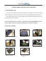
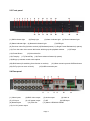
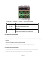
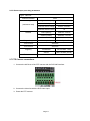
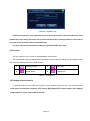
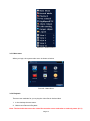
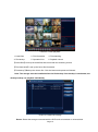
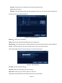
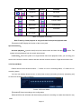
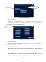
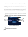
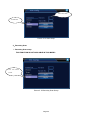
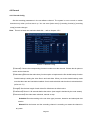
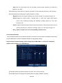
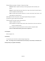
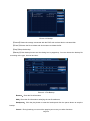
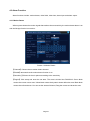
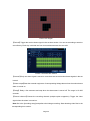
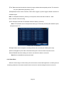
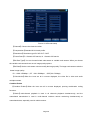
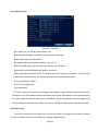
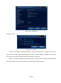
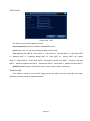
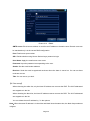
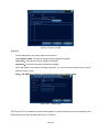
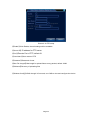
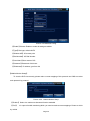
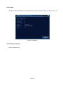
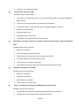
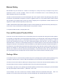
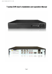
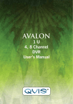
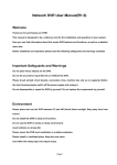
C series DVR Systems User’s installation And Operation Manual Edition R1.0 Welcome Thank you for purchasing our DVR! This manual is designed to be a reference tool for the installation and operation of your system. Here you can find information about the C series DVR’s features and functions, as well as a detailed menu tree. Before installation and operation, please read the following safeguards and warnings carefully! Important Safeguards and Warnings Do not place heavy objects on the DVR. Do not let any solid or liquid fall onto or infiltrate the DVR. Please keep the units fans clean. Before cleaning the fans please turn off the DVR. Do not disassemble or repair the DVR by yourself. Do not replace the components by yourself. Environment Avoid placing the unit in direct sunlight. Keep it away from sources of heat. Do not install the DVR in damp environment. Do not use the DVR in smoky or dusty environment. Please insure the DVR level installation in a stable workplace. Please install in ventilated area. Use within the rating input and output scope. Page 1 Directory 1 Production Introduction ............................................................................................................................ 5 1.1 Product overview ........................................................................................................................... 5 1.2 Main functions ............................................................................................................................... 5 2 Open-package check and cable connections.......................................................................................... 7 2.1 Open-package check..................................................................................................................... 7 2.2 Hard disk installation ..................................................................................................................... 7 2.3 Front panel..................................................................................................................................... 8 2.4 Rear panel ..................................................................................................................................... 8 2.5 Audio and video input and output connections ............................................................................. 9 2.5.1 Video input connections ...................................................................................................... 9 2.5.2 Video output connections and options ................................................................................ 9 2.5.3 Audio signal input .............................................................................................................. 10 2.5.4 Audio signal output ............................................................................................................ 10 2.6 Alarm input and output connections ............................................................................................ 10 2.6.1 Alarm input port specification ............................................................................................ 10 2.6.2 Alarm output port specification .......................................................................................... 10 2.6.3 Alarm output port relay parameters....................................................................................11 2.7 Speed dome connections .............................................................................................................11 3 Basic operation ...................................................................................................................................... 12 3.1 Turn on......................................................................................................................................... 12 3.2 Turn off ......................................................................................................................................... 12 3.3 System Login ............................................................................................................................... 12 3.4 Preview ........................................................................................................................................ 13 3.5 Desktop shortcut menu ............................................................................................................... 13 3.5.1 Main menu......................................................................................................................... 14 3.5.2 Playback ............................................................................................................................ 14 3.5.3 Record Mode ..................................................................................................................... 20 3.5.4 Alarm output ...................................................................................................................... 21 3.5.5 PTZ control ........................................................................................................................ 21 3.5.6 Color setting ...................................................................................................................... 23 3.5.7 Output adjust ..................................................................................................................... 23 3.5.8 Logout ............................................................................................................................... 23 3.5.9 Window switch................................................................................................................... 24 4 Main menu ............................................................................................................................................. 25 4.1 Main menu navigation ................................................................................................................. 25 4.2 Record ......................................................................................................................................... 31 4.2.1 Record Config ................................................................................................................... 31 4.2.2 Snapshot Storage.............................................................................................................32 4.2.3 Playback ............................................................................................................................ 33 4.2.4 Backup .............................................................................................................................. 33 4.3 Alarm ............................................................................................................................................ 31 4.3.1 Motion Detect .................................................................................................................... 31 4.3.2 Video Blind ........................................................................................................................ 33 4.3.3 Video Loss ......................................................................................................................... 34 Page 2 4.3.4 Alarm input ........................................................................................................................ 35 4.3.5 Alarm output ...................................................................................................................... 35 4.3.6 Abnormal ........................................................................................................................... 35 4.4 System ......................................................................................................................................... 40 4.4.1 General .............................................................................................................................. 40 4.4.2 Encode .............................................................................................................................. 41 4.4.3 Network ............................................................................................................................. 43 4.4.4 NetSevice .......................................................................................................................... 43 4.4.5 GUI Display ....................................................................................................................... 50 4.4.6 PTZ .................................................................................................................................... 51 4.4.7 RS232 ............................................................................................................................... 52 4.4.8 Tour.................................................................................................................................... 52 4.5 Advanced ..................................................................................................................................... 53 4.5.1 HDD Manage..................................................................................................................... 53 4.5.2 Account .............................................................................................................................. 53 4.5.3 Online user ........................................................................................................................ 56 4.5.4 Output adjust ..................................................................................................................... 56 4.5.5 Auto maintain..................................................................................................................... 56 4.5.6 Restore .............................................................................................................................. 55 4.5.7 Upgrade............................................................................................................................. 57 4.5.8 Device Info........................................................................................................................58 4.6 Info ............................................................................................................................................... 56 4.6.1 HDD info ............................................................................................................................ 56 4.6.2 BPS ................................................................................................................................... 57 4.6.3 Log..................................................................................................................................... 58 4.6.4 Version .............................................................................................................................. 59 4.7 Shut down system ....................................................................................................................... 59 5 FAQ and maintenance ........................................................................................................................... 60 5.1 FAQ.............................................................................................................................................. 60 5.2 Maintenance ................................................................................................................................ 65 Appendix 1.Remote controller operation .................................................................................................. 66 Appendix 2.Mouse operation .................................................................................................................... 67 Appendix 3.Hard disk capability calculation ............................................................................................. 68 Appendix 4.Technique parameters ........................................................................................................... 69 Warranty Policy …………………….…………………………………………………………………………….71 Page 3 1 Production Introduction 1.1 Product overview This DVR uses standard H.264mp video compression format and G.711A audio compression format which insures the high quality image, low error coding ratio and single frame playing. It uses TCP/IP network technology which achieves the strong network communication ability and telecommunication ability. The series DVR can be used individually or online applied as a part of a safety surveillance network. With the professional network video surveillance software it achieves the strong network communication ability and telecommunication ability. 1.2 Main functions Real-time surveillance Analog interface and VGA interface (VGA interface is equipped selectively) Surveillance function through monitor or display Storage Non-working hard disk dormancy processing which is convenient to radiate heat, reduce power and extend the life-span Special storage format which insures the data safety Compression Real-time compression by individual hard disk which insures the audio and video signal stable synchronization Backup Video and audio is saved via a SATA connected hard drive inside the unit. Video can be pulled off of the machine via a USB stick or via the net Playback Individual real-time video recording as well as searching, playback, network surveillance, recording check, downloading and so on Multi-playback mode Page 4 Net operating Through net tele-surveillance in the real time Tele-PTZ control Tele-recording check and real-time playback Alarm linkage Multi-route relay alarm output which is convenient for the alarm linkage and light control at the spot Protecting circuits at the alarm input and output interface which protects the main machine from damage Communication interface RS485 interface which fulfills the alarm input and PTZ control Standard ethernet network interface which fulfills the telecommuting function intelligent operating Mouse action function Fast copy and paste operating for the same setting Page 5 2 Open-package check and cable connections 2.1 Open-package check First, please check whether there is any visible damage to the package. The protective materials used for the package of the DVR can protect it from most accidental damage caused during transport. Next, please open the box and remove the plastic protective materials. Check whether there is any visible damage to the DVR’s exterior. The serial number label in the real panel is very important. Please DO NOT REMOVE IT from the machine. Doing so will make it impossible to identify your unit with the manufacturer. 2.2 Hard disk installation ① Remove the cover screws ④Attach hard drive screws ⑦Replace the cover ②Remove the cover ⑤Connect the SATA cable ⑧Insert the case screws Page 6 ③Attach hard drive screws ⑥Connect the power cable 2.3 Front panel (1) Shift indicator light (2)Ready light (3) Alarm indicator light (4) Record indicator light (5) Status indicator light (6) Network Indicator Light (7) HDD light (8) Previous video file (9) Hold to rewind (10) Backward pause (11) Single Frame Backwards (in pause) (12) From the main video screen this button will bring up the playback window (14) Power Button (16) Fast play (13) Escape (15) Next video file (17) Pause/Play (18) Frame advance forward (in pause) (19) Brings up camera record mode options (20) Shift button (for switching from function to number) (22) IR Eye (do not cover or block) (21) Menu arrow keys and OK/Enter button (23) USB connection port 2.4 Rear panel (1) Video inputs (2) BNC video output (3) Audio output (5) 12V Input (6) 12V power output (7) SD (9) Network port (10) VGA Out (4) Audio In (8) USB input (11) Alarm & RS232 & RS485 (12) 2 x 12V power output Page 7 2.5 Audio and video input and output connections 2.5.1 Video input connections The video input port is BNC connector plug. The demand of input signal is PAL/NTSC BNC (1.0VP-P, 75Ω). Insure the transmission line stable For video transmission, a high quality shielded RG-59 cable should be used. The length of the wire run to the camera should be no longer than 1000’ as a rule of thumb. If the transmission distance is too far, you should adopt shielded twisted pair and an active video balun to transmit your video signal. The video signal line should be away from the electromagnetic Interference such as 110V wires or stringing the cable over florescent lights. Insure the connections are tight Insure the video lines are connected properly and secured on tight so as not to cause improper video display. 2.5.2 Video output connections and options The video output is divided into PAL/NTSC BNC (1.0VP-P, 75Ω) and VGA output (selective configuration). Things to keep in mind about your monitor: 1、Do not leave your monitor running 24 hours a day if avoidable. 2、Keep the computer display normal working by degaussing regularly. 3、Keep the monitor away from electromagnetic Interference if possible. 2.5.3 Audio signal input The audio in port is a RCA connection with high input impedance. The audio signal line should be firmly connected and kept away from the electromagnetic Interference. High voltage lines should be especially avoided. 2.5.4 Audio signal output The output parameter of DVR audio signal is greater than 200mv 1KΩ (BNC) which can be used to Page 8 connect to low impedance earphones, computer speakers or other standard audio input equipment. If the speakers and microphone cannot be isolated from each other, a howling phenomena is often exhibited. There are some methods to deal with the above phenomena. 1、 Adopt better directional microphone. 2、 Adjust the speaker volume to be under the threshold that produces the howling phenomena. 3、 Use fitment materials that absorb the sound to reduce reflection of the sound. 2.6 Alarm input and output connections 1、Alarm input A. Alarm input is grounding alarm input. B. When the alarm device is connected with two DVRs, or connected with DVR and other equipment, it should be isolated by a relay. 2、Alarm output The alarm output cannot be connected with a high-power load (no more than 1A). 3、PTZ decoder connections A. The grounding of the PTZ decoder and DVR must be shared otherwise the common-mode voltage will lead to the PTZ control failure. B. Avoid the introduction of high voltage to the input. C. In the outlying end connect 120Ω resistance paralleled to reduce the inflection and insure the signal quality. D. The 485 AB lines of DVR cannot connect with other 485 output equipments paralleled. E. The voltage between the AB lines of the input must be less than 5V. 4、Front equipment grounding note Bad grounding can lead to the burnout of the chip. 5、Alarm input type unlimited The DVR alarm output port is normally open Page 9 (1) Alarm input (2) grounding (3) RS232 (4) alarm output (5) RS485 parameter G C1、NO1 meaning grounding Alarm output interface(normally open) T、R RS232 port A、B 485communication interface which is connected with the recording control equipments such as the decoder 2.6.1 Alarm input port specification 1 channel alarm input. Alarm input type unlimited. The grounding and the com port of the alarm sensor are parallel (The alarm sensor is externally powered). The ground of the alarm and the DVR should be shared. The NC port of the alarm sensor must be connected with the DVR alarm input port. 2.6.2 Alarm output port specification 1 channel alarm output. An external power source will be needed to power your alarm device. Please refer to the relay relevant parameters to avoid overloading the DVR. Page 10 2.6.3 Alarm output port relay parameters Type:JRC-27F Interface material silver rating Rating switch capacity 30VDC 2A, 125VAC (resistance load) maximal switch power 125VA 1A160W maximal switch voltage 250VAC, 220VDC maximal switch current 1A Homo-polarity 1000VAC 1minute Inhomo-polarity interface 1000VAC 1 minute Interface and winding interface 1000VAC 1 minute Surge voltage Homo-polarity 1500VAC (10×160us) Turn-on time interface isolation Turn-off time longevity 3ms max 3ms max mechanical 50×106 MIN(3Hz) electric 200×103 MIN (0.5Hz) Environment -40~+70℃ temperature 2.7 PTZ Camera connections 1、Connect the 485 lines of the PTZ camera with the DVR 485 interface. 2、Connect the video line with the DVR video input. 3、Power the PTZ camera. Page 11 3 Basic operation Note: The button in gray display indicates an inactive function and not supported on some models. 3.1 Powering the DVR Plug the power supply in and turn on the power supply switch located on the back of the machine. After the startup you will hear a beep. The default setting of video output is multiple-window output mode. . Note: 1. Make sure that the input voltage corresponds with the switch of the DVR power supply. 2. The power supply demands 110V power. It is suggested that you attach the unit to a UPS if possible. 3.2 Turning the machine off There are two methods to turn off the DVR. Entering [main menu] and choosing [turn off] in the [turn off the system] option is called soft switch, or flipping the power supply switch on the back which is called a hard switch. Illumination: 1、Auto resume after power failure If the DVR is shut down abnormally, it will automatically resume recording once power is restored. 2、Replacing the hard disk Before replacing the hard disk, the power supply switch in the real panel must be turned off. 3.3 System Login To log into the machine, right click anywhere in the background to bring up a list of options. Some of the options will require a login and password. By default, there are 2 login names, ADMIN, and GUEST with no password used. Page 12 Picture 3.1 System Login Password protection: If the password input is wrong three times, the alarm will start. If the password is input wrong five times, the account will be locked. (Through reboot or after half an hour, the account will be unlocked automatically). For your system security, please modify your password after first login. 3.4 Preview You can right click your mouse to switch between the windows. The system date, time and channel name are shown in each viewing window. The surveillance video and the alarm status are shown in each window. 1 Recording status 3 Video loss 2 Motion detect 4 Camera lock Table 3.1 Preview icon 3.5 Desktop shortcut menu In preview mode you can right click mouse to get a desktop shortcut menu. The menu includes: main menu, record mode, playback, PTZ control, High Speed PTZ, Alarm Output, color Setting, Output adjust, Logout, view1/4/8/9/16 screens. Page 13 Picture 3.2 Shortcut Menu 3.5.1 Main menu When you login, the system main menu is shown as below. Picture3.3 Main Menu 3.5.2 Playback There are two methods for you to play the video files in the hard disk. 1、 In the desktop shortcut menu. 2、 Main menu>Record->Playback Note: The hard disk that saves the video files must be set as read-write or read-only state. (4.5.1) Page 14 Picture 3.4 video playback 1. Listed files 2. File information 3. File searching 4. File backup 5. Operation hint 6. Playback control 【Listed files】Look up the listed files that accord with the searching criteria. 【File information】Look up the found file information. 【File backup】Backup the chosen file. Click the button and operate as followed. Note: The storage must be installed before the file backup. If the backup is terminated, the already backup can playback individually. Picture 3.5 detect the storage Detect: Detect the storage connected with the DVR such as hard disk or universal disk. Page 15 Erasure: Choose the file to delete and click erase to delete the file. Stop: Stop the backup. Backup: Click the backup button and the dialog box will pop up. You can choose the backup file according to the type, channel and time. Picture 3.6 recording backup Remove:Clear the file information. Add:Show the file information satisfying the set file attributes. Start/Pause:Click the play button to start the backup and click the pause button to stop the backup. Cancel:During backup you can exit the page layout to carry out other functions. 【File searching】Search the file according to the search parameters. Picture 3.7 file searching File type: Set the searching file type. Channel: Select the channel(s) you wish to search. Start Time: Set the time you wish to start your search at. 【Playback control】Refer to the following sheet for more information. Page 16 Button Function Button Function Play/pause Backward Stop Slow play Fast play Previous frame Next frame Previous file Next file Circulation / Full screen Table 3.2 Playback control key Note: Frame by frame playback is only performed in the pause playback state. 【Operation hint】Display the function of the cursor place. Special functions: Accurate playback:Input the time (h/m/s) in the time column and then click play button. The system will start playback from the search time entered. Local zoom:When the system is in single-window full-screen playback mode, you can drag your mouse in the screen to select a section and then left click mouse to zoom in. Right click mouse to exit. 3.5.3 Record Mode Please check current channel status: “○” means it is not in recording status, “●” means it is in recording status. You can use desktop shortcut menu or click [main menu]> [recording function]> [recording set] to enter the recording control interface. Picture 3.8 Record Mode 【Schedule】Record according to the configuration. 【Manual】Click the all button and the according channel is recording no matter the channel in any state. Page 17 【Stop】Click the stop button and the according channel stops recording no matter the channel in any state. 3.5.4 Alarm output Please check current channel status: “○” means it is not in alarm status, “●” means it is in alarm status. You can use the desktop shortcut menu or click [main menu]> [alarm function]> [alarm output] to enter the alarm output interface. Picture 3.9 alarm output 【Configuration】Alarm output is enabled or disabled according to the configuration selected. 【Manual】Click the all button and the according channel is alarming no matter the channel in any state. 【Stop】Click the stop button and the according channel stops alarming no matter the channel in any state. 3.5.5 PTZ control The functions include: PTZ direction control, step, zoom, focus, iris, setup operation, tour between spots, trail patrol, boundary scan, assistant switch, light switch, level rotation and so on. Note1. Decoder a (B) line connects with DVR a (B) line. The connection is right. 2. Click [main menu] >[system configuration] >[PTZ setup] to set the PTZ parameters. 3. The PTZ functions are decided by the PTZ protocols. Page 18 Picture 3.10 PTZ setup 【Speed】Set the PTZ rotation speed. Default range: 1 ~ 8. 【Zoom】Click / button to adjust the zoom multiple of the camera. 【Focus】Click / button to adjust the focus of the camera . 【Iris】Click / button to adjust the iris of the camera. 【Direction control】Control the PTZ rotation. 8 directions of control is supported. (4 directions only if you are using just the front panel buttons) 【Set】Enter the function operation menu. 【Page switch】Switch between different pages. Special functions: 1、Preset Set a location for the preset, calls the preset points, PTZ automatically turns to the setting position 1)Preset option Setting a preset location for the presets is done as follows: Step1: in Picture 3.10, click the directional buttons until the camera is in the position you want to set as a preset. Click the Settings button: refer to enter Picture 3.11. Step 2: Click the Preset button, and then type in the preset number in (i.e. preset position number 1). Step 3: Click the Set button to save your choices. Clear Preset:Input preset points, click Remove button, remove the preset。 Page 19 Preset point input blank Preset button Picture 3.11 Preset Settings 2)Preset Point Calling In Picture 3.10, click Page Shift button, enter PTZ control interface as shown in Picture 3.12. In the input blank, write the preset point you wish the camera to turn to, then click preset button. The PTZ should turn to the corresponding preset point. Value input blank Picture 3.12 PTZ Control 2、Cruise between Points Multiple preset points can be connected to form a “cruise” or a “tour”. This will make the PTZ jump from point to point in a continuous cycle. 1)Cruise between Points Settings Before setting up a tour, you must have all of your presets already set up. The setup procedure is as follows: Step1: In Picture 3.10, Click the “set” button. Step 2: Refer to picture 3.13 Select the Tour button. In the patrol number section put a 1. This means you are setting up tour number 1. You can have multiple tours set up if you wish. Page 20 Step 3: In the preset number field type in the first preset location you with the camera to pan to then hit “add preset”. Step 4: Repeat steps 1 and 2, until you have selected all of the presets you want in the tour. REMEMBER: The order you input your presets is the order the camera will cycle thru them. If you make a mistake just select “Del Tour” and start over. Step 5: Once you exit out of this screen and back to picture 3.10. Once there, click the page switch button until you are in the PTZ control window displayed in figure 3.12. Input the tour number you wish the camera to run then hit the tour button. The camera should start cycling thru all of the presets in the tour you selected. Remove Preset:You can delete presets from the system by pressing the Preset button, thping in the preset number and hitting delete. Remove Tour:Select the tour function on the left (picture 3.13) Input the number where it says Patrol No., then select delete tour. Preset Points Blank Cruise Button Cruise Line Blank Picture 3.13 Cruise between Points Settings 3、Scan PTZ also can work on the preset scan line repeatedly. 1)Scan setup Step1:THIS FUNCTION IS NOT AVAILABLE IN THIS MODEL. Page 21 Scan value blank Scan Button Picture 3.14 Scan Setup 4、Boundary Scan 1)Boundary Scan setup THIS FUNCTION IS NOT AVAILABLE IN THIS MODEL. Line scan button border Picture 3.15 Boundary Scan Setup Page 22 3.5.6 Color setting Set the selective image parameters (current channel for single window display and cursor place for multi-window display). You can use the desktop shortcut menu and enter the interface. The image parameters include: tonality, brightness, contrast, saturation. You can set different parameters at different time sections. Picture 3.18 Color Setting 3.5.7 Output Adjust Adjust TV output area parameters. You can use the desktop shortcut menu or enter [main menu]> [management tools]> [Output adjust]. Picture 3.19 Output Adjust 3.5.8 Logout Logout shut down the system or reboot up. You can use the desktop shortcut menu or enter [main menu]. Page 23 Picture 3.20 Logout/Shutdown/Reboot the system 【logout】Quit the menu. Offer password next entrance. 【shut down】Quit the system. Turn off the power supply. When press the shut down button, there is schedule hint. After three seconds, the system is shut down. Cancel midway is of no effect. 【reboot】Quit the system. Reboot up the system.. 3.5.9 Window switch Preview in single window/four windows/eight windows/nine windows/sixteen windows according to your choice. Page 24 4 Main menu 4.1 Main menu navigation Main menu Record Sub menu Function Config Set the recording configuration, recording type, recording time section playback Set recording look-up, recording play, video file storage backup Detect or format backup equipment, back the selective files Set motion detect alarm channel, sensitivity, area, linkage parameters: Motion defending time section, alarm output, screen hint, recording, PTZ, detection patrol Set camera mask alarm channel, sensitivity, linkage parameters: Video defending time section, alarm output, screen hint, recording, PTZ, blind patrol Alarm Video Set video loss alarm channel, linkage parameters: defending time loss section, alarm output, screen hint, recording, PTZ, patrol Set alarm input channel, equipment type, linkage parameters: Alarm defending time section, alarm output, screen hint, recording, PTZ, input patrol Alarm output Set alarm mode: configuration, manual, shut down General Set system time, data format, language, hard disk full time operation, configuration machine number, video format, output mode, summertime, stay time Set main(assistant)coding parameter: code mode, resolving ability, Encode System frame rate, code stream control, image quality type, code stream configuration value, frame between value, video/audio enable configuration Network Set basic network parameters, DHCP and DNS parameters, network configuration high speed download NetService PPPOE、NTP、Email、IP purview、DDNS parameter Page 25 Set channel name, preview hint icon state, transparency, cover area, GUI display time title, channel time fold PTZ Set channel, PTZ protocol, address, baud rate, date bit, stop bit, check configuration Serial port Configuration Set serial port function, baud rate, date bit, stop bit, check (RS232) Tour Set channel switching intervals for main or spot monitors Hard disk Set appointed hard disk as read-write disc, read-only disc or management redundant disc, clear data, resume date and so on User Modify user, team or password. Add user or team. Delete user or management team. Break the connection with the already login user. Lock the account Online user after break until booting up again. Management tools TV adjust Adjust TV upside, downside, nearside, starboard distance Automatic Set automatic reboot system and automatic deleting files. maintenance Resume setup state: common setup, code setup, recording setup, Restore alarm setup, network setup, network service, preview playback, serial port setup, user management Hard disk Display hard disk capability and recording time information Code stream Display code stream information System statistics information Log Clear all log information according to the log video and time information Edition Display edition information information Shut down Logout, shut down or reboot Page 26 4.2 Record 4.2.1 Record Config Set the recording parameters in the surveillance channel. The system is set to record on motion detection only when you first start it up. You can enter [main menu]> [recording function]> [recording setup] to make changes. Note:There is at least one read-write hard disk.(refer to chapter 4.5.1) Picture 4.1 Record Config 【Channel】Choose the corresponding channel number to set the channel. Choose the all option to set the entire channels. 【Redundancy】Choose the redundancy function option to implement the file double backup function. Double backup is writing the video files in two hard disks. When you do the double backup, make sure that there are two hard disks installed. One is read-write disk and the other is redundant disk. (refer to 4.5.1) 【Length】Set the time length of each video file. 60minutes is default value. 【PreRecord】Record 1-30 seconds before the action. (time length is decided by the code stream) 【Record mode】Set video state: schedule, manual or stop. Schedule:Record according to the set video type (common, detection and alarm)and time section. Manual:Click the button and the according channel is recording no matter the channel in any state. Page 27 Stop:Click the stop button and the according channel stops recording no matter the channel in any state. 【Period】Set the time section of common recording, The recording will start only in the set range. 【Record type】Set recording type: regular, detection or alarm. Regular:Perform the regular recording in the set time section. The video file type is “R”. Detect:Trigger the “motion detect”, “camera mask” or “video loss” signal. When above alarm is set as opening recording, the “detection recording” state is on. The video file type is “M”. Alarm:Trigger the external alarm signal in the set time section. When above alarm is set as opening recording, the “detection recording” state is on. The video file type is “A”. Note:Refer to chapter 4.3 to set corresponding alarm function. 4.2.2 Snapshot Storage Setup snapshot parameters for different channels. At first time it's set for 24hours snapshot continuously, pls go to Main Menu->Record->Snapshot Storage for appropriate settings. Note:If normal snapshot storage, pleases setup Snap at Main Menu -> Advanced ->Snapshot (please refer to chapter 4.5.1 HDD Manage) Picture 4.2 【Channel】Select the related channel to set,click "all" to set all channels. 【Presnap】Setup Pre-snap picture quantity before recording, Default is 5 pieces. Page 28 【Record】Set record status, "Schedule", "Manual" and "Stop" Schedule: Realise snapshot according to record type(regular, detect and alarm) and period. Manual: No matter what the present channel is in a state, Once choose "manual" button, it will have snapshot at related channels. Stop: No matter what the present channel is in a state, Once choose "stop" button, it will stop snapshot at related channels. 【Period】Set normal record period, it only startup Snapshot Storage at set period. 【Type】Three types: regular, detect and alarm 【Record type】Three types: regular, detect and alarm Regular: snapshot at set period Detect snapshot at set period when motion detect, video blind and video loss which are preset for snapshot enable. Alarm: snapshot at set period when alarm in which is preset for snapshot enable. Note: for related alarm function, please refer to chapter 4.3. 4.2.3 Playback Refer to chapter 3.5.2. 4.2.4 Backup You can back up the video files to external storage through setup. Note:The storage must be installed before the file backup. If the backup is terminated, the already backup can playback individually. Page 29 Picture 4.3 Backup 【Detect】Detect the storage connected with the DVR such as hard disk or universal disk. 【Erase】Choose the file to delete and click erasure to delete the file. 【Stop】Stop the backup. 【Backup】Click backup button and the dialog box is popped up. You can choose the backup file according to the type, channel and time. Picture 4.4 File Backup Remove:Clear the file information. Add:Show the file information satisfying the set file attributes. Start/pause:Click the play button to start the backup and click the pause button to stop the backup. Cancel:During backup you can exit the page layout to carry out other functions. Page 30 4.3 Alarm Function Alarm functions include: motion detect, video blind, video loss, alarm input and alarm output. 4.3.1 Motion Detect When system detects the motion signal that reaches the set sensitivity, the motion detect alarm is on and the linkage function is turned on. Picture 4.4 Motion Detect 【Channel】Choose the set motion detect channel. 【Enable】■ means that the motion detect function is on. 【Sensitivity】Choose in the six options according to the sensitivity. 【Region】Click setup and enter the set area. The area is divided into PAL22X18. Green block means the current cursor area. Yellow block means the dynamic detect defensive area. Black block means the unfenced area. You can set the area as followed, Drag the mouse and draw the area. Page 31 Picture 4.5 Region 【Period】Trigger the motion detect signal in the set time section. You can set according to week or set uniformly. Each day is divided into four time sections.■ means the set valid. Picture 4.6 set the time section 【Interval】Only one alarm signal is turned on even there are several motion detect signals in the set interval. 【Alarm output】Start the external equipment of corresponding linkage alarm when the motion detect alarm is turned on. 【Delay】Delay a few moments and stop when the alarm state is turned off. The range is 10~300 seconds. 【Record channel】Choose the recording channel (multiple option supportive). Trigger the video signal when the alarm is turned on. Note:Set in the [recording setup] and perform the linkage recording. Start detecting video files in the corresponding time section. Page 32 【Tour】■ means that the selective channel is single window alternate patrol preview. The interval is set in the [Main Menu]>[System] > [Tour]. 【Snapshot】Choose record channels, when alarm triggers, System triggers related channels for snapshot signal. Note: For Snapshot activation, please go to set period, detect and alarm enable at Main Menu->Record->Record Config, 【PTZ Activation】Set the PTZ activation when the alarm is turned on. Note: PTZ activation is set in the [shortcut menu] >[ PTZ control]. Set the patrol between spots, trail patrol and so on. Picture 4.8 PTZ Activation 【Delay】When alarm is stopped, recording will last some seconds(10~300sec),then stop. 【Show message】Pop the alarm information dialog box in the local host computer screen. 【Send EMAIL】■ means sending an email to user when the alarm is turned on. Note:Set in the [NetService] and send email. 4.3.2 Video Blind When the video image is influenced by the environment such as bad brightness or reaching the set sensitivity parameter, the camera mask function is turned on and the linkage function is turned on. Page 33 Picture 4.9 Video Blind Set method: refer to chapter 4.3.1. Motion detect Note:"Advanced" button is the same as right click. 4.3.3 Video Loss When the equipment cannot obtain the channel video signal, the video loss alarm is turned on and the linkage function is turned on. Picture 4.10 Video loss Set method: refer to chapter 4.3.1. Motion detect Note:"Advanced" button is the same as right click. Page 34 4.3.4 Alarm input When the equipment obtains the external alarm signal, the alarm function is turned on. Picture 4.11 Alarm input Set method: refer to chapter 4.3.1. Motion detect Note:"Advanced" button is the same as right click. 4.3.5 Alarm output Refer to chapter 3.5.4. 4.3.6 Abnormal Analyzing and inspecting current software and hardware of the device: When some abnormal events happened, the device will make a relative answer such as show message and buzzer. Picture 4.12 Abnormal Page 35 【Event Type】 selecting abnormity you want to inspect 【Enable】 Select it to make sure abnormal function workable 【Show message】 Automatically alarm cue dialog box come out of the main screen Device will have two long nosie “di di” while alarm is happening 【Buzzer】 4.4 System setup Set the system parameters such as General, Encode, NetWork, NetService, GUI display, PTZ config, RS232 and Tour setup. 4.4.1 General Picture 4.13 General setup 【System time】Set the system data and time. 【Date format】Choose the data format: YMD, MDY, DMY. 【Date Separator】Choose list separator of the data format. 【Time Format】Choose time format: 24-hour or 12-hour. 【Language】English, French, Portuguese, Russian, Italian, S-Chinese, T-Chinese, Spanish, Thai, Greek, Japanese, German, Polish. 【HDD full】Choose stop record: Stop recording when the hard disk is full. Choose overwrite: Cover the earliest recording files and continue recording when the hard disk is full. Page 36 【DVR No.】Only when the address button in the remote controller and the corresponding DVR number is matched, the remote operation is valid. 【Video Standard】PAL or NTSC. 【Auto Logout】Set the latency time in 0-60. 0 means no latency time. 【DST】Choose the summer time option and pop the dialog box as followed. Picture 4.14 DST (week) Picture 4.15 DST (date) 4.4.2 Encode setup Set the video/audio code parameter: video file, remote monitoring and so on. Set every independent channel’s coding parameter in the left part, and set the combine encode parameter in the right part. Note: Combine encode introduces video compression technique which combines and compresses multi-channel’s video to a special channel. Applying for multi-channel playback simultaneously, Dial-up multi-channel real-time monitor, mobile monitor and so on. Page 37 Picture 4.16 Encode setup 【Channel】Choose the channel number. 【Compression】Standard H.264 main profile. 【Resolution】Resolution type:D1/ HD1/CIF / QCIF. 【Frame Rate】P:1 frame/s~25 frame/s; N: 1 frame/s~30 frame/s 【Bit Rate Type】You can choose limited code stream or variable code stream. When you choose the variable code stream there are six image quality options. 【Bit Rate】Set the code stream value to modify the image quality. The larger code stream value the better image quality. D1(1000~1500kbps),CIF(384~1500kbps), QCIF(64~512kbps) 【Video/Audio】When the icons are all in reverse displayed, the video file is video and audio multiplex stream. Combine Enable 【Combine Enable】When the icons are all in reverse displayed, opening combination coding functions. 【 Mode 】 multi-channel playback is used in all channels playback simultaneously, and the narrowband transmission is used in multi-channel real-time remote monitoring simultaneously at narrowband state, especially used in mobile monitor. Page 38 4.4.3 Network setup Picture4.17 Network 【Net Card】You can choose cable network card 【DHCP Enable】Obtain IP address automatically(not suggested) Note:DHCP server is preinstalled. 【IP address】Set the IP address. Default: 192.168.1.10. 【Subnet mask】Set the subnet mask code. Default: 255.255.255.0. 【Gateway】Set the default gateway. Default: 192.168.1.1. 【DNS setup】Domain Name Server. It translates the domain name into IP address. The IP address is offered by network provider. The address must be set and reboot then it works. 【TCP port】Default: 34567. 【HTTP port】Default: 80. 【HS Download】 【Transfer Policy】There are three strategies: self-adaption, image quality precedence and fluency precedence. The code stream will adjust according to the setup. Self-adaption is the tradeoff between the image quality precedence and fluency precedence. Fluency precedence and self-adaption are valid only when the assistant code stream is turned on. Otherwise image quality precedence is valid. 4.4.4 Net Service Choose the network service option and click the set button to configure the advanced network functions or double click the service button to configure the parameters. Page 39 Picture 4.18 NetService 【PPPoE setup】 Picture4.19 PPPOE Input the user name and password that ISP(Internet service provider)provides. After saving it reboot up your system. Then the DVR will build a network connection based on PPPoE. The IP address will change into dynamic IP address after above operation is well done. Operation:After PPPoE dialing successfully look up the IP address in the [IP address] and obtain the current IP address. Then use this IP address to visit the DVR through user port. Page 40 【NTP setup】 Picture 4.20 NTP The NTP server must be installed in the PC. Host computer IP:Input the IP address installed NTP server. Port:Default: 123. You can set the port according to NTP server. Time zone:London GMT+0 Berlin GMT +1 Cairo GMT +2 Moscow GMT +3 New Delhi GMT +5 Bangkok GMT +7 Hongkong Beijing GMT +8 Tokyo GMT +9 Sydney GMT +10 Hawaii GMT-10 Alaska GMT-9 Pacific time GMT-8 American mountain time GMT-7 American mid time GMT-6 American eastern time GMT-5 Atlantic time GMT-4 Brazil GMT-3 Atlantic mid time GMT-2. Update Period:The same with the NTP server check interval. Default: 10minutes. 【EMAIL setup】 If the alarm is turned on or the alarm linkage photos are taken, send an email about the alarm information and the photos to appointed address. Page 41 Picture 4.21 EMAIL SMTP server: Email server address. It could be an IP address or domain name. Domain name can be translated only it is the correct DNS configuration. Port: Email server port number. SSL: Decide whether using Secure Socket Layer protocol to login. User Name: Apply the email server user name. Password :Input the password corresponding to the user. Sender: Set the email sender address. Receiver: Send the email to appointed receivers when the alarm is turned on. You can set three receivers at most. Title: You can set as you wish. 【IP Filter setup】 When choosing the white list, only the listed IP address can connect the DVR. The 64 IP addressed are supportive in the list. When choosing the black list, the listed IP address cannot connect the DVR. The 64 IP addressed are supportive in the list. You can delete the set IP address by √ in the options. Note:When the same IP address is in the white and black list at the same time, the black list precedence is higher. Page 42 Picture 4.22 IP IP FILTER 【DDNS】 It is the abbreviation of dynamic domain name server. Local domain name:Provide the domain name registered by DDNS. User name:Provide the account registered by DDNS. Password:Provide the password registered by DDNS. When the DDNS is successfully configured and start, you can connect the domain name in the IE address column to visit. Note:The DNS setup must be configured correctly in the network setup. Picture 4.23 DDNS setup 【FTP setup】FTP is available only when alarm happens, or alarm activates record and snapshot, it will upload related record and snapshot pictures to FTP server. Page 43 Picture 4.24 FTP setup 【Enable】Click Enable, then all settings will be available 【Server IP】IP address for FTP server 【Port】Domain Port of FTP, default 21 【User Name】User name of FTP 【Password】Password of user 【Max File Length】Max length for upload files at every packed, default 128M 【DirName】Directory of uploading files 【Wireless Config】ADSL through 3G net card, use CMS to view and configure the device Page 44 Picture 4.25 Wireless Config 【Enable】Choose Enable to make all settings available 【Type】Dial type, default AUTO 【Wireless AP】3G access point 【Dial Number】3G Dial Number 【User Name】User name of 3G 【Password】Password of dial user 【IP Address】IP address, got from dial 【Mobile Monitor Setup】 To view the DVR via remotely, please make a router mapping of this port and use CMS to monitor and operate it by protocol. Picture 4.26 Mobile Monitor Setup 【Enable】 Select it to make sure abnormal function workable 【Port】 It’s a port of mobile monitoring which you need to make a router mapping of if want to visit it by mobile Page 45 【UPNP】UPNP protocol can auto port forwarding on router, make sure UPNP is running on router before use it. Picture 4.27 【Enable】Choose Enable to make sure all UPNP settings available 【HTTP】Route will automatically distribute HTTP port for the device, when IE viewing, it need this port (eg. 60.12.9.26:66) 【TCP】Router will automatically distribute TCP port for the device, when monitoring via CMS, it need this port. 【MobilePort】Router will automatically distribute Mobile Port for the device, when mobile monitor, it need this port. 4.4.5 GUI Display Configure the video output parameters including the front output mode and code output mode. Front output:In the local preview mode include: channel title, time display, channel title, record status, alarm status, bit rate info, transparency and region cover. Code output:In the network surveillance and video file mode include: channel title, time display, channel title, record status, alarm status, bit rate info, transparency and region cover. Page 46 Picture 4.28 GUI Display 【Channel Title】Click the channel name modify button and enter the channel name menu. Modify the channel name. The 16 Chinese characters and 25 letters are supportive. 【Time Display】means the selective state. Display the system data and time in the surveillance window. 【Channel Title】means the selective state. Display the system channel number in the surveillance window. 【Record Status】means the selective state. Display the system recording status in the surveillance window. 【Alarm Status】means the selective state. Display the system alarm status in the surveillance window. 【Bitrate info】means the selective state. The ninth window displays the code stream information in the nine-window preview status. 【Transparency】Choose the background image transparency. The range is 128~255. 【Resolution】set display resolution. 【Channel】Choose the set code output channel number. 【Region Cover】means the selective state. Click the cover area button and enter the corresponding channel window. You can cover the arbitrary using mouse. (Black region is for output) 【Time display】and 【Channel Title】 Page 47 4.4.6 PTZ setup Picture 4.29 PTZ setup 【Channel】Choose the dome camera input channel. 【Protocol】Choose the corresponding dome protocol. (PELCOD as an example) 【Address】Set as the corresponding dome address. Default: 1.(Note:The address must be consistent with the dome address.) 【Baudrate】Choose the corresponding dome baud rate length of the PTZ camera. Default: 115200. 【Data bits】Include 5-8 options. Default: 8. 【Stop bits】Include 2 options. Default: 1. 【Parity】Include odd check, even check, sign check, blank check. Default: void. Page 48 4.4.7 RS232 setup Picture 4.30 RS232 setup 【Serial Port Function】Common serial port is used to debug and update program or set up specific serial port. 【Baud rate】Choose the corresponding baud rate length. 【Data bits】Include 5-8 options. 【Stop bits】Include 2 options. 【Parity】Include odd, even, mark, space. 4.4.8 Tour setup Set the patrol display. Means that the tour mode is turned on. You can choose the single window, four windows, nine windows; sixteen windows patrol display or single display. Page 49 Picture 4.31 tour setup 【interval】Set the patrol switch interval. The set range is 5-120 seconds. Note: / means turn off/on the patrol. 4.5 Advanced 4.5.1 HDD Manage Configure and manage the hard disk. The menu displays current hard disk information: hard disk number, input port, type, status and overall capability. The operation include: setup the write-read disk, read-only disk, redundant disk, hard disk format, resume default. Choose the hard disk and click the right function button to execute. Note:Read/Write Disk: The equipment can write or read data. Read-only Disk: The equipment can read data but cannot write data. Redundant Disk: Double backup the video files in the write-read disk. Page 50 Picture4.32 HDD Manage 4.5.2 Account Manage the user accounts Note:1. The character length is 8 bytes at most for the following user and user team name. The blank ahead or behind the character string is invalid. The middle blank in the character string is valid. Legal characters include: letter, number, underline, subtraction sign, dot. 2. There is no limit in the user and user group. You can add or delete the user group according to user definition. The factory setup include: user\admin. You can set the team as you wish. The user can appoint the rights in the group. 3. The user management include: group/ user. The group and user name cannot be the same. Each user only belongs to one group. Page 51 Picture 4.33 Account 【Modify User】Modify the existing user attribute. 【Modify Group】Modify the existing team attribute. 【Modify Password】Modify the user password. You can set 1-6 bit password. The blank ahead or behind the char string is invalid. The middle blank in the char string is valid. Note:The user who has the user control rights can modify his/her own or other users password Picture 4.34 Modify Password 【Add user】Add a user in the team and set the user rights. Enter the menu interface and input the user name and password. Choose the team and choose whether cover using the user. Cover using means that the account can be used by multiple users at the same time. Once the team is selected, the user rights is the subclass of the team. Page 52 We recommend that the common user’s right is lower than the advanced user. Picture 4.35 add user 【Add Group】Add a user team and set the rights. There are 36 different rights: shut down the equipment, real time surveillance, playback, recording setup, video file backup and so on. Picture 4.36 Add Group 【Delete User】Delete the current user. Choose the user and click delete user button. 【Delete Group】Delete the current group. Choose the group and click delete group button. Page 53 Picture 4.37 Delete Group 4.5.3 Online User Look up the network user information in the local DVR. You can choose the network user and disconnect the connection. Then the user is locked until next boot-strap. Picture 4.38 Online User 4.5.4 TV adjust Refer to chapter 3.5.7 . Page 54 4.5.5 Auto Maintain The user can set the auto reboot time and auto file deleting time limit. Picture 4.39 Auto maintain 4.5.6 Restore The system restore to the default setup. You can choose the items according to the menu. Picture 4.40 Restore Page 55 4.5.7 Upgrade Picture 4.41 Upgrade 【Upgrade】choose USB interface. 【Upgrade file】choose the file which needs upgraded. 4.5.8 Device Info Provide device interface info like audio in, alarm in/out to be conveniently used for user. Picture 4.42 Device Info. 4.6 Info 4.6.1 HDD info Display the hard disk state: hard disk type, overall capability, residual capability, the recording time and so on. Page 56 Picture 4.43 HDD Info Clue:○ means that the hard disk is normal. X - means that the hard disk is non-functional or damaged. - means that there is no hard disk. If the user needs to change the damaged hard disk, you must shut down the DVR and take up all the damaged hard disks, then install a new one. * behind serial number means the current working disk such as 1*. If the corresponding disk is damaged, the information will show “?”. 4.6.2 BPS Display the code stream(Kb/S)and hard disk capability (MB/H)in real time. It displays as the wave sketch map. Page 57 Picture 4.44 BPS 4.6.3 LOG Look up system log according to the set mode. Log information include: system operation, configuration operation, data management, alarm affair, recording operation, user management, and file management and so on. Set the time section to look up and click the look up button. The log information will display as a list. (one page is 128 items) Press Page up or Page down button to look up and press delete button to clear all the log information. Picture4.45 LOG Page 58 4.6.4 Version Display the basic information such as hardware information, software edition, issue data and so on. Picture 4.46 Version 4.7 Shut down system Refer to chapter 3.5.8. Page 59 5. FAQ and maintenance 5.1 FAQ Note: If the problem on your DVR is not listed, please contact your local vendor. The DVR system has a one year warranty service and technical support starting from the date of purchase. Contact your vendor for details of your warranty policy. 1、 The DVR will not boot up normally. Possible reasons are as followed: 1 The power supply is not correct 2 DC power supply line does not have a good connection or no power on AC wall outlet. 3 DC power supply is damaged. 4 The program updating is wrong. 5 The hard disk is damaged or the hard disk has bad sectors on its disk. 6 The front panel is damaged. 7 The main board of the DVR is damaged. 2、 The DVR reboots automatically or stops working a few minutes after boot up. Possible reasons are as followed: 1 The AC or DC input voltage is not stable or too low. 2 The hard disk is damaged or the hard disks have bad sectors on its disk plates. 3 Frontal video signal is not stable. 4 Bad heat radiator or too much dust or bad running circumstance for the DVR. 5 The hardware of the DVR is damaged. 3、 System cannot detect hard disk. Possible reasons are as followed: 1 The hard disk power supply line is not connected. 2 The data cables of the hard disk are damaged or loosely connected 3 The hard disk is damaged. 4 The SATA port of main board is damaged. 4、 There are no video outputs in single channel, multiple channels and all channels. Page 60 Possible reasons are as followed: 1 The firmware program is wrong. Please update the firmware program. 2 The image brightness is all 0. Please restore the default setup. 3 There is no video input signal, you have a bad camera or the signal is too weak. 4 The channel protection or the screen protection is set. 5 The hardware of the DVR is damaged. 5、 Real-time image problems such as the image color or the brightness distortion. Possible reasons are as followed: 1 When using the BNC output, the option between the N mode or PAL mode is wrong and the image becomes black and white. 2 The DVR is not matched the monitor impedance. 3 The video transmission distance is too far or the loss of the video transmission line is too large. 4 The color and brightness setting of the DVR is wrong. 6、 I cannot find the video files in local playback mode. Possible reasons are as followed: 1 The data line of the hard disk is damaged. 2 The hard disk is damaged. 3 Update the different program with the original program files. 4 The video files to look up are already overwritten by the DVR system. 5 The recording is not on or may have been setup wrong. 7、 The local video is not clear. Possible reasons are as followed: 1 The image quality is too bad. 2 The reading program is wrong. Reboot up the DVR. 3 The data line of the hard disk is damaged. 4 The hard disk is damaged. 5 The hardware of the DVR is damaged. 8、 There is no audio signal in the surveillance window. Possible reasons are as followed: Page 61 1 There is no microphone connected to DVR. 2 There are no speakers connected to DVR. 3 The audio lines are damaged. 4 The hardware of the DVR is damaged. 9、 There is audio signal in the surveillance window but no audio signal in the playback state. Possible reasons are as followed: 10、 1 Setting issues: the audio option is not enabled or not setup right. 2 The camera channel is not connected with the right video. The time is wrong. Possible reasons are as followed: 11、 1 Setting of date/time is wrong. 2 The battery is in bad connection or the voltage is too low. You may need new battery. 3 The oscillation is damaged. The DVR cannot control the PTZ. Possible reasons are as followed: 1 There is something wrong with the PTZ camera. 2 The setting, connection or the installation of the PTZ decoder is not correct. 3 The wiring connections are not correct. 4 The PTZ setting at the DVR is not correct. 5 The protocols of the PTZ decoder and the DVR do not matched. 6 The address of the PTZ decoder and the DVR does not match. 7 When multiple decoders are connected, the far port of the PTZ decoder RS485 line A (B) must have a 120 resistance to reduce the reflection otherwise the PTZ control is not stable. 8 12、 The wiring distance is too far. The motion detect is not working, Possible reasons are as followed: 1 The time range set is not correct. 2 The motion detect area setup is not correct. 3 The sensitivity is too low. Page 62 4 13、 Limited by some hardware edition. I cannot login via web or CMS. Possible reasons are as followed: 1 The system is windows 98 or Win me. We recommend updating to windows 2000sp4 or higher Version. 2 14、 ActiveX is not setup right with your Internet Explorer Options. 3 The DirectX version is not higher than dx8.1. Update the display card driver. 4 Network connection failure. 5 Network setting issues. 6 Invalid password or user name. 7 The CMS is not matched the DVR program version. The image is not clear or there is no image in network preview state or video file playback state. Possible reasons are as followed: 15、 1 Network is not stable. 2 The user machine is resource limited. 3 Choose the play-in-team mode in the network setup of DVR. 4 The region shelter or channel protection is set. 5 The user has no surveillance view right. 6 The real-time image of the hard disk recording machine itself is not clear. Network connection is not stable. Possible reasons are as followed: 16、 1 Network is not stable. 2 IP address is conflicted. 3 MAC address is conflicted. 4 The net card of the DVR is bad. There is something wrong with the USB backup or writing a CD. Possible reasons are as followed: 1 The rewritable machine and the hard disk are shared the same data lines. 2 The data is too much. Please stop recording and backup. Page 63 17、 3 The data exceeds the backup storage. 4 The backup equipment is not compatible. 5 The backup equipment is damaged. The keyboard cannot control the DVR. Possible reasons are as followed: 1 The serial port of the DVR is not set correctly. 2 The address is not correct. 3 When multiple transformers are connected, the power supply is not large enough. Please give each transformer individual power supply. 4 18、 The distance is too far. Alarm will not stop Possible reasons are as followed: 19、 1 The setting of the alarm is not correct. 2 The alarm output is turned on manually. 3 The input machine is damaged or the connections are not correct. 4 There are some problems for specific program edition, Please update the program. Alarm is not working. Possible reasons are as followed: 20、 1 The setting of the alarm is not correct. 2 The connection of the alarm is not correct. 3 The alarm input signal is not correct. 4 A alarm is connected with two loops synchronously. The remote controller is not working, Possible reasons are as followed: 21、 1 The remote control address is not correct. 2 The remote control distance is too far or the angle is too large. 3 The battery is used up. 4 The remote controller or the front panel of the recording machine is damaged. The storage time is not enough. Possible reasons are as followed: Page 64 22、 1 Video quality from camera is bad. The lens is too dirty. The camera is in backlighting option. 2 The hard disk capability is not enough. 3 The hard disk is damaged. The downloaded files will not play. Possible reasons are as followed: 1 There is no media player. 2 There is no DX8.1 software or higher edition. 3 There is no DivX503Bundle.exe file to play AVI video files. 4 The DivX503Bundle.exe and ffdshow-2004 1012 .exe files must be installed in the windows PC system. 23、 I cannot remember the advanced code or network code in the local menu operation. Please contact the local vendor. 5.2 Maintenance 1 Please use Air can spray to clean printed circuit boards, connectors, fans, machine box and so on regularly. 2 Please keep the grounding well done to prevent the video or audio signal interfered and the DVR from static or inductive electricity. 3 Do not connect/disconnect the video signal line or RS-232 port or RS-485 port with the power on. 4 Do not use the TV in the local video output port(VOUT) of DVR. It will damage the video output circuit easily. 5 Do not turn off the power switch directly. Please use the turn-off function in the menu or press the turn-off button in the panel (3 seconds or longer) to protect the hard disk. 6 Please keep the DVR away from heat and humid. 7 Please keep the DVR ventilated. Please check the system and maintain regularly. Page 65 Appendix 1.Remote controller operation (1) Serial (2) (3) (4) (5) (6) (7) (8) Name Function Multi-window Same function as Multi-window button in the front number 1 button panel 2 Numeric button Code input/number input/channel switch 3 【Esc】 4 Direction button Same function as direction button in the front panel 5 Record control Control the record 6 Record mode Same function as “Record mode” 7 ADD 8 FN Same function as【Esc】button in the front panel Input the number of DVR to control it Assistant function Page 66 Appendix 2.Mouse operation *used right handed mouse as an example The mouse in USB connection is supported. Operation Function Double click one item in the file list to playback the video Double click the playback video to zoom in or out the Double left click screen Double click the channel to make it full screen display double click again to resume the multi-window display Left click Right click Choose the according function in the menu Pop desktop shortcut menu in preview state Current shortcut menu in the menu Press middle button Add or subtract number in the number setting Switch the items in the combo box Page up or down in the list Move mouse Choose the widget or move the item in the widget Set the motion detect area Drag mouse Set the cover area Page 67 Appendix 3.Hard disk capability calculation Make sure the hard disk installed to the DVR for the first time. Pay attention to the IDE hard disk lines connection. 1、 Hard disk capability There is no limit for recording machine. We recommend 120G~250G size to keep better stability. 2、 Overall capability option The hard disk capability formula is: Overall capability(M)=channel number*time(hour)*capability in an hour(M/hour) The recording time formula is: overall capability(M) Recording time(hour)= Capability in an hour(M/hour)*channel number The DVR introduces the H.264 compression technology. Its dynamic range is very large so the hard disk capability calculation is based on the estimation values of each channel creating files in an hour. Example: For one piece 500G HDD, real time CIF for recording, it will keep recording for about 25 days.HDD spaces per channel is 200M/H, if 4channels real time CIF at 24hours recording uninterrupted, it can last:500G/(200M/H*24H*4ch)=26 days Page 68 Appendix 4.Technique parameters Type System 4ch 8ch 16ch Main processor High performance embedded microprocessor Operation system Embedded LINUX operation system System resource synchronous multi-channel recording, synchronous multi-channel sub-code stream, synchronous multi-channel playback, synchronous network operation Operation interface 16 bit true color graphical menu interface, mouse operation supportive Interface display 1/4image display 1/4/8/9 image display 1/4/8/9/16 image display Video standard PAL 625line,50 f/s;NTSC 525 line,60 f/s Surveillance image PAL, D1(704x576);NTSC, D1(704x480) quality Playback image PAL,D1(704×576);NTSC, D1(704*480) quality Video Video compression H.264 mp Video control 6 options Recording speed 100/120fps (D1) 200/240fps(CIF), 400/480fps CIF 50/60fps D1 Motion detect 396(22×18) detection areas, multiple sensitivity Audio compression G711A Bidrectional Talk Support Recording mode manual >alarm>motion detect>timing Playback Any channels playback, multiple channels playback Audio Record And Page 69 Playback Search mode Time searching, calendar searching, affair searching, channel searching, information searching Space Occupation Audio: 28.8MB/H Video:25~450MB/H And Recording storage Hard disk, network backup Backup mode Network, USB flash,USB movable HDD,USB DVD-RW Storage Video input 4 BNC 8 BNC Video output Audio input 1 BNC, 1 VGA 4 RCA 1 RCA Audio output Alarm input 16 BNC 1 RCA 4ch 1ch Port Alarm output 1channel Network port RJ45 10M/100M PTZ control port 1 RS485 USB port 2* USB2.0 ports Hard disk port 1 SATA port Power supply 12V/4A external power supply Power consumption <15W (without hard disk) Working temp. 0℃~+55℃ Working humidity 10%-90% Air pressure 86kpa-106kpa Size 310(width)x215(depth)x45(height)mm Weight 3kg(without hard disk) Installation Desktop Other Page 70 Return Policy Merchandise may be returned for a refund or exchange for 15 days from day of receipt as long as the equipment is still in "as new" condition. There is no return on Clearance items. A 15% restocking fee may apply. Shipping costs are not refundable. "As New" means that all items must be undamaged and in their original cartons and packaging along with all accessories, documentation, and parts. No wires or pigtails can be cut. The product exterior must be intact and unmarked. The original carton must be in another "shipping" box. No postmarks or labels shall be on the original box. Cable must be unopened (or still on reel). A Return Merchandise Authorization (RMA) number must be obtained from Discount Security Cameras prior to the return of any merchandise. An RMA number is only valid for 14 days. To request an RMA number, call (904) 855-1121. Free and Discounted Product Offers From time to time, DSC will offer a free or discounted product as a special offer along with another product. For example, we might offer a free monitor with a DVR system. In a case like this, if the product is returned (eg, the DVR system) then the free or discounted product must also be returned (eg, the monitor) in order to receive the full refund for the order. The free or discounted product must also be in 'as new' condition as described above. If the free or discounted product(s) is not returned with the rest of the order then DSC will charge the customer for the retail price of the free product (or the difference between the discounted price vs. the retail price of the discounted product) thereby reducing the amount that the customer would receive in the refund. For example, if a free monitor was not returned and the retail price of the monitor is $129 then the refund to the customer would be reduced by $129.Similarly, if a discounted monitor was not returned which was sold at $59 that was normally $159, then the refund to the customer would be reduced by $100. Package Offers If a customer returns an item that was purchased as part of a package (and so paid a reduced package price) or using an order discount or coupon, DGP will calculate the correct amount to be refunded as follows: The total cost of the items will be added up according to the price if each item was purchased separately. Then the percentage of discount will be calculated based on the price paid for the package. For example, if the items in the package purchased separately is $750 and the package price paid was $699 then the percentage of discount was 1 - (699/750) * 100 = 6.8%. In this example, if an item is returned, the amount credited would be the individual retail price - 6.8%. For example, if one camera was returned which costs $79 individually, the refunded amount would be: Page 71 $79 - 6.8% or $79 - ($79 * .068) = $79 - $5.37 = $73.63 In this case, $73.63 was the actual amount paid for the camera given the package or coupon price. If a restocking fee is charged it will be based on this actual amount paid ($73.63 in this example). If you have any questions about this policy please feel free to call us. Warranty At Discount Security Cameras (DSC) we take pride in offering only the highest quality reliable products. In the rare event that a defect does occur we offer the following warranty: All products are warranted by Discount Security Cameras for 1 year from date of purchase, except for Clearance items which are warranted for 90 days. If a product is defective we will repair or replace it. The customer is responsible for the shipping to send the product to us. We will pay for the shipping cost to return the product back to the customer. The following situations void the product warranty: Removing the Microsoft Product License Tag and/or Serial number from the PC-based DVR and PTZ cameras; Opening the housing of any camera with a fixed lens. Cutting the connectors off on any equipment. Adding 3rd party software to a DVR without prior approval from our technical support department. Damage caused by nature such as flooding, winds, lightning and other similar events; fault of the installer or customer due to negligence (for example dropping or breaking the product, improper voltage, or improper installation causing damage; for example overheating due to lack of ventilation). After 1 year (outside of the warranty), we will continue to support the product at the standard repair labor rate (currently $65 per hour-minimum 2 hours) plus parts, if applicable, or phone technical support for $65.00/hour. Out of warranty repairs are guaranteed for 30 days. Phone support is non-refundable. Network systems can be complex and everyone's network is configured differently. For this reason Discount Security cannot be liable for any issues or problems resulting from support of network related issues. We recommend that for any network related issues, you involve the support of your local network support specialist. RMA : All returns and warranty services require a valid Returned Merchandise Authorization Number (RMA#) issued by Discount Security Cameras. An RMA number is valid for 14 days (returned products must be received within 14 days from issuance of the RMA number). To request an RMA number, call (904) 855-1121. Page 72