1
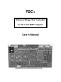
FDC+
Enhanced Floppy Disk Controller
for the Altair 8800 Computer
User’s Manual
FDC+ User’s Manual
6/16/15 v1.2
Table of Contents
1.0 Introduction.......................................................................................................................... 1
1.1 Items Included...................................................................................................................... 2
1.2 Online Resources ................................................................................................................. 2
2.0 Board Configuration ............................................................................................................ 3
2.1 Drive Type Selection and Monitor Switch........................................................................... 3
2.1.1 On-Board Monitor............................................................................................................. 4
2.2 Configuring On-Board RAM ............................................................................................... 4
2.3 Configuring On-Board PROM............................................................................................. 5
2.4 Interrupt Select Switches ..................................................................................................... 6
2.4.1 Clearing Interrupts in Software......................................................................................... 6
2.5 Configuring the I/O Address................................................................................................ 6
2.6 Phantom ............................................................................................................................... 6
3.0 Drive Types.......................................................................................................................... 8
3.1 Drive Type 0: Original Altair 8” Drive................................................................................ 8
3.2 Drive Type 1: Direct Connect to Shugart 8” drive as Altair 8” drive .................................. 8
3.2.1 Drive Configuration .......................................................................................................... 9
3.2.2 Shugart Drive Alignment .................................................................................................. 9
3.3 Drive Type 2: Original Altair Minidisk ............................................................................. 10
3.31 Minidisk “Foley” Configuration ...................................................................................... 11
3.4 Drive Type 3: Direct Connect to 5.25” drive as Altair Minidisk....................................... 11
3.4.1 Drive Configuration ........................................................................................................ 12
3.4.2 Using Newer 96 TPI 5.25” Floppy Drives as Altair Minidisk........................................ 12
3.5 Drive Type 4: 5.25” Soft-Sectored as Altair 8” Drive ...................................................... 14
3.5.1 Drive Configuration ........................................................................................................ 15
3.6 Drive Type 6 and 7: Serial Drive as Altair Minidisk, Altair 8” Drive.............................. 16
3.6.1 Serial Port........................................................................................................................ 16
3.6.2 Serial Drive Server.......................................................................................................... 16
3.6.3 Disk Image Files ............................................................................................................. 16
Appendix A – Writing a New Floppy from a Disk Image ........................................................ 17
Appendix B – PROM Content as Shipped................................................................................ 18
FDC+ User’s Manual
6/16/15 v1.2
1.0 Introduction
The Altair FDC+ is an enhanced version of the original MITS floppy disk controller for the Altair 8800.
The FDC+ is a 100% compatible drop-in replacement for the original two-board Altair FDC. The FDC+
can serve as a replacement for a missing or defective Altair FDC, or you can use the FDC+ as a reference
point while restoring original floppy equipment to working condition.
In addition to duplicating the functionality of the original MITS controller, the FDC+ provides several
enhancements:
Drop-in Replacement for the Altair Minidisk FDC
The FDC+ can be used as a drop-in replacement for the original two board Minidisk controller for the
Altair. The FDC+ can connect to a Minidisk drive cabinet or directly to the Altair Minidisk buffer
boards in an Altair 8800bt Foley configuration.
Shugart 8” Drive (or equivalent) as Altair 8” Drive
The FDC+ can connect directly to readily available Shugart SA-80x (or equivalent) drives and make
them function identically to the Altair/Pertec drive and cabinet. From the perspective of the Altair
computer and software, it appears that an Altair/Pertec drive is attached. Even the media itself is interchangeable – the Shugart can read floppies written on an Altair/Pertec drive and vice versa.
In addition to being more readily available, more reliable, and less expensive than the Altair/Pertec
drives, the Shugart drives don’t require the additional buffer board present in the Altair drive cabinet
when used with the FDC+. Just supply power and connect the Shugart drives directly to the FDC+
with a ribbon cable.
Shugart 5.25” Drive (or equivalent) as Altair Minidisk
The FDC+ can connect directly to 5.25” Shugart SA-400 (or equivalent) drives and make them function identically to the Altair Minidisk. In this configuration, the Altair buffer board is not required between the controller and the floppy drive. From the perspective of the Altair computer and software, it
appears that an Altair Minidisk cabinet is attached. When connected to 48 TPI drives, the media itself
is also interchangeable with an Altair Minidisk. 96 TPI drives can also be used, and the media will interchange between 96 TPI drives, but the 96 TPI written media won’t work in a 48 TPI drive and
vice-versa.
Soft-Sectored Floppies as a Substitute for Hard Sectored Floppies
The original Altair FDC requires hard sectored media for both the 8” (32 sector) and 5.25” (16 sector)
formats. However, the FDC+ can also work with soft sectored media. If the controller determines that
sector holes are not present as a floppy spins up, it syncs to the rotational rate of the floppy and generates virtual sector pulses so that everything else “just works.” This is done on the fly and is completely transparent to the Altair computer and software.
The soft sectored media can be exchanged between aligned drives as long as an FDC+ is used (the
soft sectored media will not work with the original Altair two-board FDC). Belt driven 8” drives like
the Shugart 80x are not reliable with soft sector media due to speed variations within a revolution.
The same speed variations exist with belt driven 5.25” drives, however, the sector timing of the
smaller drives is more forgiving so the soft sectored media tends to work reliably with the 5.25”
drives. For Altair Minidisk applications, use single or double density (SD, DD) media. When using a
newer 5.25” drive as an 8” drive (see next section), use high density (HD) media.
-1-
FDC+ User’s Manual
6/16/15 v1.2
5.25” Drive as an Altair 8” Drive
A 96 TPI, 5.25” drive, like the Teac 55-GFR, can be used with readily available soft sectored media
as a transparent replacement for an Altair 8” drive. The Altair computer and software cannot tell it’s
not connected to an original Altair 8” drive. Of course, the media is not interchangeable with an 8”
drive, but the media is interchangeable between the 5.25” drives. This allows you to run all the original Altair floppy-based software, use and handle floppy disks, but skip the hassle of repair, alignment,
and maintenance of the older 8” drives. The drives are also much smaller, less expensive, require
smaller power supplies, and the 5.25” soft sectored media is still readily available.
Serial Drive with PC Based Server (no rotating media at all)
The FDC+ includes a built-in, high speed serial port that can connect to a PC running a serial disk
server. From the perspective of the Altair computer and software, it appears that an Altair/Pertec drive
is attached. Performance of the serial drive is virtually identical to the original Altair floppy drive.
Both the Altair 8” drive and Minidisk drive are supported. Numerous disk images – available via
links on the FDC+ web page – can be mounted on the PC server and run from your Altair computer.
In addition to providing disk controller functions, the FDC+ includes up to 64K of RAM and 8K of
PROM that can be separately enabled if needed. The RAM can be enabled in 1K increments. The PROM
can be enabled in 256 byte increments.
1.1 Items Included
The following items are included with the FDC+ package:
• Floppy disk controller PCB (assembled and tested)
• 27C64 EPROM pre-programmed with a disk boot loader (CDBL), the Altair multi-boot loader
(MBL), the Altair turnkey monitor (TURMON), and an Intel hex loader.
• IDC-14 to DB-25F serial cable (for monitor access and serial disk operation)
• IDC-50 to DB-37F adapter for Altair 8” drives (connectors not provided)
• IDC-50 to IDC-26 adapter for Altair Minidisk (connectors not provided)
• IDC-50 to IDC-34 adapter for 5.25” drives (connectors not provided)
1.2 Online Resources
References in this manual to the “FDC+ web page” are referring to http://deramp.com/fdc+support.htm.
Here you’ll find the latest version of this manual, the FDC firmware, as well as links to the software and
other documents referred to in this manual.
-2-
FDC+ User’s Manual
6/16/15 v1.2
2.0 Board Configuration
Four DIP switch banks are used to configure the FDC+:
1) The Drive Type switches select the type of drive connected to the FDC+ and also enable entry into
the FDC+ monitor.
2) The RAM switches enable/disable RAM and specify the RAM starting address.
3) The PROM switches enable/disable PROM and specify both the ending address of RAM and the
starting address of PROM.
4) The Interrupt Select switches connect the interrupt output of the board to one of the vectored interrupt lines or to the PINT line on the Altair bus.
In addition to the DIP switch banks, PCB traces can be cut and wire-jumpered to change the I/O address
of the controller registers and to disable RAM/PROM from responding when *Phantom is asserted.
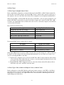
Figure 2.0 Switch and Jumper Locations
2.1 Drive Type Selection and Monitor Switch
The DIP switches for selecting the drive type are located at the top left corner of the FDC+ board. The
switch bank is labeled “Drv Type” (S3). Drive type selection is performed using the right-most four
switches labeled “3 2 1 0” on the PCB silkscreen (ignore the numbers printed on the switch itself). The
switch positions between “Mon” and drive type “3” are not used and their setting does not matter.
To set a switch to “1” press the rocker down towards the top of the PCB. To set a switch to “0” press the
rocker down towards the bottom of the PCB.
-3-
FDC+ User’s Manual
6/16/15 v1.2
3210
0000
0001
0010
0011
0100
0101
0110
0111
1000
thru
1111
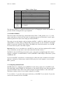
Table 2.1 Drive Types
Drive Type
Original Altair 8” drive
Direct connect to Shugart 8” drive as Altair 8” drive
Original Altair Minidisk
Direct connect to 5.25” drive as Altair Minidisk
5.25” soft-sector as Altair 8” drive
Not assigned
Serial drive as Altair Minidisk
Serial drive as Altair 8” drive
Not assigned
The drive type switches are examined and latched at power on. Changing the switches after the FDC+ is
powered on will not change the drive type assignment.
2.1.1 On-Board Monitor
The far left switch on the Drive Type switch bank is labeled “Mon.” If this switch is set to “1” (rocker
down towards the top of the board), the monitor is entered upon power up. The monitor is used to apply
firmware updates and to adjust some settings provided by the FDC+.
The monitor is accessed using the serial port built into the FDC+. An IDC-14 to DB-25 cable is provided
with the FDC+ to use this serial port. Plug the IDC-14 end of the cable onto the “Serial Port” (J2) header
which is located next to the Drive Type switches. The DB-25 end of the cable mounts in one of the DB25 cutouts in the rear panel of the Altair computer.
Important: If the cover of your Altair rests on the IDC-14 connector, and other equipment will be stacked
on top of the Altair, you may want to remove the strain relief from the connector.
The DB-25 is wired as DCE using just transmit, receive, and ground. A straight through cable connects
directly to a terminal or a terminal emulator on a PC (with DB-25 to DB-9 adapter). The monitor operates
at 9600 baud, 8N1.
Note: If ever the FDC+ seems like it’s not functioning, most likely the monitor switch has been accidentally left or switched on. Set the monitor switch off and cycle power to the computer to restore normal
FDC+ operation.
2.2 Configuring On-Board RAM
The DIP switches for configuring on-board RAM are located at the top right corner of the FDC+ board.
The switch bank is labeled “RAM” (S1). The function of each switch is labeled on the silkscreen directly
above the individual rockers. Refer to these labels and ignore the printed numbers on the switch itself.
The leftmost switch position is not used and its setting does not matter.
To set a switch to “1” press the rocker down towards the top of the PCB. To set a switch to “0” press the
rocker down towards the bottom of the PCB.
-4-
FDC+ User’s Manual
6/16/15 v1.2
The *EN switch (not enable) is used to enable or disable on-board RAM. Setting this switch to “0” enables RAM. Setting this switch to “1” disables RAM (note: this is the opposite polarity as the PROM enable switch).
The switches labeled “15” to “10” correspond to 8080 address lines A15 to A10 and are used to set the
1K address block at which RAM starts. For example, set A15-A10 all to zero to start RAM at address zero. Set A15-A10 to 1100 00 to start RAM at C000h.
The ending address of RAM is determined by the PROM starting address (minus 1) as detailed in the next
section. Even if PROM is not enabled, the ending address of RAM is determined by the PROM starting
address. Note that the maximum starting address that can be specified for PROM is FF00h. This implies
that maximum possible on-board RAM address is FEFFh (i.e., the last 256 bytes of on-board RAM are
not accessible).
2.3 Configuring On-Board PROM
The FDC+ includes a socket for a 27C64 EPROM (8K bytes). The 8K PROM is fixed in the 8080 address
space at E000h - FFFFh. The PROM switch bank determines the address within the PROM at which the
PROM starts to respond. The PROM responds from the specified starting address through FFFFh.
The DIP switches for configuring on-board PROM are located at the top right corner of the FDC+ board.
The switch bank is labeled “PROM” (S2). The function of each switch is labeled on the silkscreen directly above the individual rockers. Refer to these labels and ignore the printed numbers on the switch
itself. The two leftmost switch positions are not used and their setting does not matter.
To set a switch to “1” press the rocker down towards the top of the PCB. To set a switch to “0” press the
rocker down towards the bottom of the PCB.
The EN switch is used to enable or disable on-board PROM. Setting this switch to “1” enables the
PROM. Setting this switch to “0” disables the PROM (note: this is the opposite polarity as the RAM enable switch).
The switches labeled “12” to “8” correspond to address lines A12 to A8 and are used to select the 256
byte block within the PROM at which the PROM begins to respond. A15 to A13 are permanently asserted
as 1’s.
For example, if you want to use just the 256 byte DBL (disk boot loader) PROM, which in the original
Altair is at FF00h-FFFFh, then the DBL code should be programmed into the top 256 bytes of the 8K
27C64 EPROM (1F00h-1FFFh within the 27C64). The PROM address switches A12-A8 should all be set
to 1 1111, which when combined with A15-A13 as all ones, gives FF00h as the address at which the
PROM starts to respond.
As a second example, assume you want to include the 256 byte MBL (multi-boot loader) PROM, the 256
byte TURMON (turnkey monitor) PROM, and a 256 byte Intel hex file loader in addition to the disk boot
loader. These additional PROMs are located at FE00h, FD00h, and FC00h respectively. Burn the code of
these four PROMs into the address range 1C00h-1FFFh within the 27C64. PROM address switches A12A8 should be set to 1 1100, which when combined with A15-A13 as all ones, gives FC00h as the address
at which the PROM begins to respond.
-5-
FDC+ User’s Manual
6/16/15 v1.2
2.4 Interrupt Select Switches
Like the original Altair FDC, the FDC+ can be commanded to generate interrupts at the start of each sector. The internal interrupt signal from the FDC+ can be configured to drive vectored interrupts 0-6 or the
PINT signal on the Altair Bus. The switch bank labeled “Interrupt Select” (S4) determines which Altair
bus interrupt line is driven by the internal interrupt. The corresponding connection for each switch is labeled on the silkscreen directly below the switch bank. Refer to these labels and ignore the printed numbers on the switch itself.
To connect the internal interrupt to a particular bus interrupt, press the corresponding rocker towards the
top of the PCB for the desired bus interrupt line V0-V6 or PINT. Only one interrupt line should be selected at a time.
2.4.1 Clearing Interrupts in Software
The interrupt from the FDC+ is de-asserted as soon as the 8080 interrupt routine reads any register on the
FDC+. Note this is different than the original FDC in which the FDC interrupt is cleared by any 8080 interrupt acknowledge cycle (which could occur first for a completely different device). This “bug fix” on
the FDC+ works with all known Altair software which uses disk interrupts because the first thing a disk
interrupt routine typically does is read the sector position register. If you have an application which requires the original interrupt clear logic, please contact us.
2.5 Configuring the I/O Address
By default, the FDC+ responds to I/O addresses 8-11 as detailed in the table below. By cutting two jumper traces and installing two wire jumpers, the FDC+ can be configured to respond to an alternate set of
I/O address at 80h-83h.
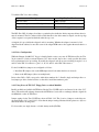
I/O Addr (Alt)
8 (80h)
9 (81h)
10 (82h)
11 (83h)
Table 2.4 I/O Addresses
Read
Drive Status
Sector Position
Read Data
Reserved
Write
Drive Select
Drive Command
Write Data
Reserved
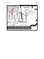
Figure 2.5 on the following page details the alternate I/O address modification. The view is from the back
(solder) side of the board.
2.6 Phantom
The FDC+ can be configured to not respond to memory reads when *Phantom is asserted. The FDC+
does not have an option to drive the *Phantom signal.
Locate the “Phantom In” feed through immediately above the card edge connector (left half of the connector when viewed from component side), and the “Phantom” feed through at the bottom right corner of
the board, just below R17. Connecting a wire between “Phantom In” and “Phantom” enables the Phantom
feature.
-6-
FDC+ User’s Manual
6/16/15 v1.2
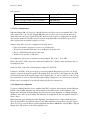
Figure 2.5 I/O Address Modification
-7-
FDC+ User’s Manual
6/16/15 v1.2
3.0 Drive Types
3.1 Drive Type 0: Original Altair 8” Drive
In the original Altair configuration, an internal cable runs from the FDC to a DB-37 female mounted in
the rear panel of the Altair computer. An external DB-37 male to female cable connects from the rear of
the computer to the rear of the Altair drive cabinet. This configuration can be duplicated with the FDC+.
When using the FDC+, an internal IDC-50 cable runs from the FDC+ to the rear panel. An adapter board
mounts in the DB-37 cutout in the rear panel of the Altair computer and converts from IDC-50 to a DB37 female. An original DB-37 male to female cable can be used to connect the computer to the disk drive,
or a new cable can be made.
Parts required for internal wiring:
Description
Digi-Key Part Number
Internal IDC-50 to IDC-50, 18 inches
M3CCA-5018J-ND
IDC-50 to DB-37 female adapter PCB
(included)
IDC-50 shrouded header, PCB mount
MHC50K-ND
DB-37 female, right angle, PCB mount
A32129-ND
2 x 4/40 screws
If an external DB-37 male to female cable is required:
Description
Digi-Key Part Number
DB-37 male, IDC
HMU37H-ND
DB-37 female, IDC
HFU37H-ND
Ribbon cable, 37 conductor
MC37G-10-ND (e.g., 10 feet)
Older Altair 8800 cabinets do not have a DB-37 cutout in the rear panel. In this case, a ribbon cable must
be draped over the top edge of the rear panel and tucked under the top cover. There are a couple of options for connecting the FDC+ to the drive:
1) Duplicate the configuration above, but leave the IDC-50 to DB-37 adapter inside the Altair cabinet
or just outside the Altair cabinet. Be sure to mount or secure the adapter such that the bottom of the
board cannot short against the metal cabinet.
2) Plug the IDC-50 to DB-37 adapter into the rear of the drive cabinet and run 50 conductor ribbon
cable all the way back to the FDC+ inside the Altair.
3.2 Drive Type 1: Direct Connect to Shugart 8” drive as Altair 8” drive
In this configuration, a single IDC-50 ribbon cable runs from the connector on the FDC+ to the 50 pin
card edge connector on up to four Shugart 800 or 801 drives. To the Altair computer and software, the
Shugart drives look identical to the original Altair drives. Even the media is interchangeable between
aligned Shugart and Altair drives.
-8-
FDC+ User’s Manual
6/16/15 v1.2
Parts required:
Description
Digi-Key Part Number
IDC-50 socket
MKC50A-ND
50 pos card edge connector, IDC (1 per drive)
MCE50K-ND
Ribbon cable, 50 conductor
MC50G-10-ND (e.g., 10 feet)
3.2.1 Drive Configuration
Either the Shugart 800 (soft sectored) or the 801 (hard sectored) drive can be used with the FDC+. The
index output of the “soft sectored” Shugart 800 still asserts for all 32 sector holes plus the index hole
when a hard sectored floppy is inserted. The 801 (hard sectored) model is not required. In fact, the 801
drive must be jumpered as an 800 (see below) since both the Altair FDC and the FDC+ expect all 33
pulses and perform sector/index separation on board.
Jumpers on the drive are used to configure the following options:
•
•
•
•
Drive select enables stepper motor but does not load the head
The head loads and unloads in response to the Head Load interface line
The door LED indicates the head loaded status
Disable sector separator on 801 drives
To configure the options above, install the following jumpers: DS, A, B, C, Y, T2, 800
Drive selects DS1 to DS4 correspond to Altair drive numbers 0 to 3. Install a single and unique drive select jumper per drive.
On the last drive on the cable, install terminator jumpers T1 and T3-T6
Unrelated to the FDC+, if the power supply you are using with the Shugart drives provides –5v, install
jumper L (bypasses the negative regulator). Depending on the board revision, this jumper may be a PCB
trace already in place. If the negative supply is more negative than –5v, remove jumper L so the –5v regulator on the drive is used. As noted, this may require cutting a jumper-trace on some versions of the drive.
Finally, remove any jumpers not specifically installed per the above instructions.
3.2.2 Shugart Drive Alignment
To prepare a Shugart 80x drive for use with the Altair FDC+, align the drive using the specified Shugart
SA120 or Dysan 360A alignment disk. After calibration, the radial (track-to-track) alignment of the
Shugart drive will match an aligned Pertec drive. However, the index alignment of a calibrated Shugart
and Pertec drive differs by about 360us. This difference is enough that media is incompatible between to
the two drives.
Rather than improperly adjusting the index alignment of the Shugart drive to make it match the Pertec
drive, the Altair FDC+ automatically adjusts for the 360us difference between the two properly aligned
drives. Note: Do not use the Pertec specified alignment disk (Pertec 600202-02 or Dysan 500) to align the
Shugart drive. This will not fix the index alignment issue.
-9-
FDC+ User’s Manual
6/16/15 v1.2
3.3 Drive Type 2: Original Altair Minidisk
In the original Altair Minidisk configuration, an internal cable runs from the FDC to a 26 pin header installed in a DB-25 cutout in the rear panel of the Altair computer. An external IDC-26 to IDC-26 ribbon
cable connects from the rear of the computer to the rear of the Minidisk cabinet. This configuration can be
duplicated with the FDC+.
When using the FDC+, an internal IDC-50 cable runs from the FDC+ to the rear panel. An adapter board
mounts in a DB-25 cutout in the rear panel of the Altair computer and converts from IDC-50 to a 26 pin
header. An original IDC-26 ribbon cable can be used to connect the computer to the Minidisk cabinet, or
a new cable can be made.
Parts required for internal wiring:
Description
Digi-Key Part Number
Internal IDC-50 to IDC-50, 18 inches
M3CCA-5018J-ND
IDC-50 to Minidisk adapter PCB
(included)
IDC-50 shrouded header, PCB mount
MHC50K-ND
26 pin dual row header
609-3367-ND
2 x 4/40 screws
4 (or 6) x 4/40 nuts (2 to 4 used as spacers)
If an external IDC-26 ribbon cable is required:
Description
Digi-Key Part Number
IDC-26 to IDC-26, 36 inches
M3BBA-2636J-ND
The connector arrangement when using the Altair Minidisk can be confusing. In the original MITS configuration, even and odd pin numbers swap at the Altair computer rear panel and swap back again at the
Minidisk rear panel. At each rear panel, two face-to-face IDC-26 sockets connect to each other with a
header between them. Because of the way IDC dual-row sockets and cables are built, this swaps even and
odd pins (assuming the pin 1 side of each connector remains on the same side through the chain of cables
and connectors).
To duplicate this configuration with the FDC+, the 26 pin header should be installed on the back side of
the adapter PCB instead of on the silkscreen side. The adapter is then mounted in a DB-25 cutout as
shown in Figure 3.3 on the next page. Use one or two nuts per mounting hole as spacers between the inside of the rear panel and the adapter PCB so the IDC-50 pins do not touch the rear panel.
Pin 1 of the 26 pin header is marked on the silkscreen side of the adapter board. The pin 1 edge of the
adapter header should align with the pin 1 edge of the ribbon cable which runs to the drive cabinet. Again,
as noted above, it is actually pin 2 of the ribbon cable that connects to pin 1 of the header – this is correct
and is reversed at the drive cabinet.
- 10 -
FDC+ User’s Manual
6/16/15 v1.2
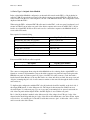
Figure 3.3 Minidisk Adapter Board Installation
3.31 Minidisk “Foley” Configuration
The Foley configuration is an Altair 8800bt (turnkey) computer, along with one or two SA-400 drives, all
mounted in the same 8800bt cabinet. In the original Foley computer, the cable from the FDC connects
directly to a header on a short ribbon cable from the first drive’s buffer board. In this case, no pin swapping occurs.
To use the FDC+ in the Foley configuration, the 26 pin header should be installed on the same side of the
board as the silkscreen (i.e., the opposite as shown in the pictures above). Then a short IDC-26 cable can
be used to connect from the header on the adapter board to the header on the buffer board cable.
3.4 Drive Type 3: Direct Connect to 5.25” drive as Altair Minidisk
In this configuration, an internal IDC-50 ribbon cable runs from the connector on the FDC+ to an IDC-34
adapter board inside the Altair computer. From the adapter board, a ribbon cable runs to the 34 pin card
edge connector on up to three Shugart SA-400 (or equivalent) drives. To the Altair computer and software, the Shugart drives look identical to the original Altair Minidisk cabinets. The media is interchangeable between aligned stand-alone drives and the Altair Minidisk drives.
Parts required for internal wiring:
Description
Digi-Key Part Number
Internal IDC-50 to IDC-50, 18 inches
M3CCA-5018J-ND
IDC-50 to IDC-34 adapter PCB
(included)
IDC-50 shrouded header, PCB mount
MHC50K-ND
IDC-34 shrouded header, PCB mount
MHC34K-ND
- 11 -
FDC+ User’s Manual
6/16/15 v1.2
To build the IDC-34 to drive cabling:
Description
Digi-Key Part Number
IDC-34 socket
MKC34A-ND
34 pos card edge connector, IDC (1 per drive)
MCE34K-ND
Ribbon cable, 34 conductor
MC34G-10-ND (e.g., 10 feet)
The IDC-50 to IDC-34 adapter board has no particular place inside the Altair computer cabinet where it
must be mounted. The 34 conductor ribbon cable that runs to the drives must be draped over the top edge
of the computer’s rear panel and tucked under the top cover.
A single hole is provided in the adapter board for mounting. Whether the adapter is mounted or left
draped inside the cabinet, be sure the bottom of the adapter PCB cannot short against the metal chassis or
cabinet.
3.4.1 Drive Configuration
While the Shugart SA-400 5.25” floppy is detailed in this section, most any 48 TPI drive will work. The
34 pin connector is fairly consistent between 5.25” drive models, but be sure to study specific drive interface requirements before proceeding. If needed, the adapter board allows custom wiring from pins 2, 4, 6,
and 34 on the IDC-34 connector to pins 2, 8, 16, 22, and 32 on the IDC-50 connector.
For the SA-400, drive jumpers are configured as follows:
• Install the HL jumper, remove the MH jumper (head loads when the drive is selected)
• Remove the MX jumper (drives are multiplexed)
Drive selects DS1 to DS3 correspond to Altair drive numbers 0 to 2. Install a single and unique drive select jumper per drive. On the last drive on the cable, install the terminator pack.
3.4.2 Using Newer 96 TPI 5.25” Floppy Drives as Altair Minidisk
Readily available and reliable 96 TPI drives like the Teac 55-GFR can be used instead of the older 5.25”
drives. The media will exchange between the 96 TPI drives, but it will not exchange with the original Altair Minidisk or other 48 TPI drives.
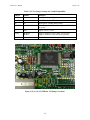
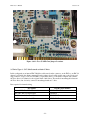
Jumper settings for the Teac 55-GFR are shown in Table 3.4.2. The location of jumpers on the drive are
shown in Figures 3.4.2-1 and 3.4.2-2. Note that the jumper settings illustrated in the picture are different
than listed in the following table.
For best results, use single density or double density media (SD/DD).
- 12 -
FDC+ User’s Manual
6/16/15 v1.2
Table 3.4.2 Teac Jumper Settings for SA-400 Compatibility
Jumper
In/Out
Function
LG
In
Not HD mode (pin 2 high / not driven)
I
In
300 RPM when not HD mode
E2
In
Index pulses continue while seeking
DS0-DS3
Install for drive #
0-2 = Shugart 1-3, DS3 on P6 – jumper to IDC-50 P32
if needed.
IU
Out
Ignore “In Use” on P4
U0,U1
Both Out
Both In
Light on with drive select (either option is fine)
Light on with drive select and motor spinning
RY, DC
Out
Neither Ready or Disk Change drive P34
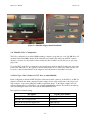
Figure 3.4.2-1 Teac 55-GFR-149, -159 Jumper Locations
- 13 -
FDC+ User’s Manual
6/16/15 v1.2
Figure 3.4.2-2 Teac 55-GFR-7xxx Jumper Locations
3.5 Drive Type 4: 5.25” Soft-Sectored as Altair 8” Drive
In this configuration, an internal IDC-50 ribbon cable runs from the connector on the FDC+ to an IDC-34
adapter board inside the Altair computer. From the adapter board, a ribbon cable runs to the 34 pin card
edge connector on up to four Teac 55-GFR (or equivalent) drives. To the Altair computer and software,
the Teac drives look identical to the original Altair 8 inch drives. The media is interchangeable between
the Teac drives, but obviously, cannot be interchanged with an 8” drive.
Parts required for internal wiring:
Description
Digi-Key Part Number
Internal IDC-50 to IDC-50, 18 inches
M3DDA-5018J-ND
IDC-50 to IDC-34 adapter PCB
(included)
IDC-50 shrouded header, PCB mount
MHC50K-ND
IDC-34 shrouded header, PCB mount
MHC34K-ND
- 14 -
FDC+ User’s Manual
6/16/15 v1.2
To build the IDC-34 to drive cabling:
Description
Digi-Key Part Number
IDC-34 socket
HKR34H-ND
34 pos card edge connector, IDC (1 per drive)
MCE34K-ND
Ribbon cable, 34 conductor
MC34G-10-ND (e.g., 10 feet)
The IDC-50 to IDC-34 adapter board has no particular place inside the Altair computer cabinet where it
must be mounted. The 34 conductor ribbon cable that runs to the drives must be draped over the top edge
of the computer’s rear panel and tucked under the top cover.
A single hole is provided in the adapter board for mounting. Whether the adapter is mounted or left
draped inside the cabinet, be sure the bottom of the adapter PCB cannot short against the metal chassis or
cabinet.
3.5.1 Drive Configuration
The TEAC 55-GFR series of 5.25” drives can be configured to run at 360 RPM to match the rotation rate
of 8” drives. The drives provide 80 tracks (there are 77 tracks on 8” drives), and the motor speed is very
stable, so generating 32 virtual hard sectors for soft sectored media is reliable.
Jumper settings for the Teac 55-GFR running as an 8” drive are shown in Table 3.5.1. The location of
jumpers on the drive are shown in Figures 3.4.2-1 and 3.4.2-2. Note that the jumper settings illustrated in
the picture are different than listed in the following table.
For best results, use High Density (HD) media.
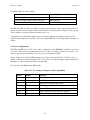
Table 3.5.1 Teac Jumper Settings for 8 inch Compatibility
Jumper
In/Out
Function
LG
Out
HD mode (pin 2 high / not driven)
I
Out
360 RPM
E2
In
Index pulses continue while seeking
DS0-DS3
Install for drive #
0-2 = Shugart 1-3, DS3 on P6 – jumper to IDC-50 P32
IU
Out
Ignore “In Use” on P4
U0,U1
In
Light on with drive select and motor spinning
RY, DC
Out
Neither Ready or Disk Change drive P34
- 15 -
FDC+ User’s Manual
6/16/15 v1.2
3.6 Drive Type 6 and 7: Serial Drive as Altair Minidisk, Altair 8” Drive
In this configuration, the FDC+ does not hook to a drive at all. Instead, the high-speed serial port on the
FDC+ is connected to a PC running a disk image server. From the perspective of the Altair computer and
software, it appears that an Altair drive is attached. Performance of the serial drive is virtually identical to
the original Altair floppy drives.
3.6.1 Serial Port
The same serial port on the FDC+ is used for the monitor and for the serial drive feature. An IDC-14 to
DB-25 cable is provided with the FDC+ to use this serial port. Plug the IDC-14 end of the cable onto the
“Serial Port” (J2) header which is located next to the Drive Type switches. The DB-25 end of the cable
mounts in one of the DB-25 cutouts in the rear panel of the Altair computer.
Important: If the cover of your Altair rests on the IDC-14 connector, and other equipment will be stacked
on top of the Altair, you may want to remove the strain relief from the connector.
The DB-25 is wired as DCE using just transmit, receive, and ground. A standard DB-25 to DB-9 serial
cable for a PC works for connecting the Altair to the PC (i.e., null modem not required).
The serial drive can operate at one of three baud rates: 403.2K, 460.8K, or 230.4K baud. Baud rates are
changed on the FDC+ using the monitor. These fast baud rates will most likely require a computer running a USB-to-serial adapter as opposed to a native serial port. The default and first choice for baud rate
is 403.2K. If his baud rate is not available on the PC, a more standard 460.K baud is the second choice.
Finally, if neither of these rates is available on the PC, 230.4K baud can be used. At 230.4K baud, disk
operation is slightly slower than the actual 8 inch drive. The Altair Minidisk still functions at full speed.
3.6.2 Serial Drive Server
The serial drive server for Windows is available from the FDC+ web page. Download the zip file and
simply drag the “Altair Server.exe” file onto the desktop. No installation is required. Additional instructions for the server program are in readme file included in the zip file.
3.6.3 Disk Image Files
Numerous disk image files of original Altair software are available via links on the FDC+ web page. Images files have a .dsk extension. You can also recognize disk images by their file size. 8 inch disk images
are 330K, Minidisk images are 75K.
- 16 -
FDC+ User’s Manual
6/16/15 v1.2
Appendix A – Writing a New Floppy from a Disk Image
Numerous disk images of original Altair software are available for download via links on the FDC+ web
page. These images can be written directly to real floppies whenever needed.
The program PC2Flop is utility that runs on the Altair computer and writes a full floppy from a disk image received over a 2SIO serial port. The image is transferred from a PC using the XMODEM protocol. A
terminal emulator like TeraTerm is typically used on the PC for transferring the disk image files.
PC2Flop runs stand-alone or under CP/M. Even when running under CP/M, the disk being written can be
any type of disk (e.g., Altair BASIC, Altair DOS, CP/M, etc.)
Even if you have no disks with software on them, you can:
1) Load PC2Flop into RAM and run it stand-alone to create a bootable CP/M 2.2 disk.
2) Once you have a CP/M disk, PC2Flop is most easily run from under CP/M to create any additional
disks you need (Altair BASIC, Altair DOS, etc).
Two versions of PC2Flop for the Altair are available: One for 8” floppies (330K disk image files) and one
for Minidisk floppies (75K image files). The programs are available for download via the FDC+ web
page. Detailed instructions are included in the readme file with each download. Note that in addition to
the “loader” technique described in the readme file for getting PC2Flop running on a machine with no
boot disk, you can also use the Intel hex file loader present in the PROM on the FDC+. See Appendix B.
Running the 2SIO at 19,200 baud
A very simple modification to the 2SIO board allows it to run at 19,200 baud. This speeds up the disk
image transfer process substantially. See the FDC+ web page for instructions on performing this modification.
File Transfer Utilities PCGET and PCPUT
In addition to using PC2Flop to write entire disk images, the programs PCGET and PCPUT provide individual file transfer to/from an Altair running CP/M. PCGET retrieves a file from a PC onto the Altair and
PCPUT writes a file from the Altair to the PC. Files are transferred using the XMODEM protocol via a
2SIO serial port.
The PCGET and PCPUT programs are already on most of the CP/M disk images. They can also be downloaded independently via the link for software for the 8” drive on the FDC+ web page: CPM > CPM 2.2 >
Programs > PCGet and PCPut.
Terminal Emulator for Windows PCs
TeraTerm is an excellent terminal emulator for working with vintage PCs as a console and for file transfer. A link to the emulator is provided on the FDC+ web page.
- 17 -
FDC+ User’s Manual
6/16/15 v1.2
Appendix B – PROM Content as Shipped
The 27C64 EPROM on the FDC+ is shipped pre-programmed with some typical Altair PROM content:
FF00:
FE00:
FD00:
FC00:
Combined Disk Boot Loader (CDBL)
Altair Multi-Boot Loader (MBL, boots cassette tapes, paper tapes)
Altair Turnkey Monitor (TURMON)
Intel Hex file loader
MITS provided a disk boot loader PROM for the Altair 8” drive, and a different boot loader PROM for
Altair Minidisk. Unfortunately, both of these PROMs are located at FF00, so you can’t install PROMs for
both type of drives at the same time. Martin Eberhard wrote a combined disk boot loader (CDBL), that
can boot either type of disk. This is the PROM at FF00.
The MBL and TURMON PROMs are the original Altair PROMs. Note that TURMON places its stack at
F800, so RAM must be present just below F800. The FDC+ RAM can be enabled to fill this area of
memory space if required.
Intel hex files can be loaded through the first port on a 2SIO board by jumping to address FC00. The operator is prompted to send the hex file and the loader displays address information as the load progresses.
Once the file transfer is complete, the loader idles in an endless loop. The loader places its stack at 8000h,
so RAM must be present just below 8000h. The FDC+ RAM can be enabled to fill this area of memory
space if required.
More information about these PROMS can be found on the FDC+ web page.
- 18 -