1
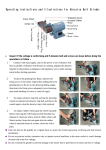
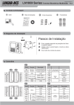
OA1000 Series Multimedia fingerprint terminal
V1.2
Package List
2 Instruction Package
1 Reader
or
FOR
EN
COMPACT
CH
CD
OM
Connector Jack
Accessory Package
windows
Windows 98
Windows 2000
Windows XP
Windows Vista
Windows 7
C
d
ar
产品外观Appearance
Reader
State Switch
Camera
Prompt:Please refer to the
User Manual in the disk for
details
Confirm & Navigation
LCD
Shortcut Key
Fingerprint Sensor
Num. & Letter
Card Reader Area
State Switch
Camera
Menu
Delete
EXIT & Power On/Off
Enter management interface:
Input ID
0
1 Press “0” and [OK]
Password
12345
Confirm & Navigation
LCD
Shortcut Key
Fingerprint Sensor
Num. & Letter
2 Input default password 12345
3 Press [OK] enter
Menu
Correct method:
Place finger in the center of
the sensor.
Delete
EXIT & Power On/Off
Incorrect method:
Place finger flatly and
smoothly on the sensor.
Place finger away from
the center of the sensor.
Tilt sensor.
Use fingertip.
Operation Guide
Enroll User:
Main
Enroll
User
Application
Setting
2012-03-09 08:08:16
Select [User]
Main User
Data
Advanced
ESC/Back
User Add
Registered
Users
1
Fingerprints
1
Press [OK]
Add
Modify
Del
2012-03-09 08:08:16
Press [OK]
Search
ESC/Back
Select [Add]
ID
Name
Password
Card No.
Dept
Admin
Group ID
Enroll FP
2012-03-09 08:08:16
hqtrs
No
0-NC
Picture
Mode
Menu/Save ESC/Back
Please input user information and follow with voice
prompt to enroll fingerprint Press[M] to save and exit.
OA1000 Series Multimedia fingerprint terminal
V1.2
Set Communication parameter:
Main
Enroll
User
Application
Advanced Comm
Main Advanced
Data
Setting
Snapshot
Press [OK]
Mode
Time Zone
Access
Advanced
2012-03-09 08:08:16
Comm.
Press [OK]
Group
2012-03-09 08:08:16
ESC/Back
Com
Limit
Static
RJ45
192.168.0.7
192.168.0.218
255.055.255.0
192.168.0.1
192.168.0.1
2012-03-09 08:08:16
ESC/Back
Select [Comm.]
Select [Advanced]
Comm.
Real-time monitor
Retrieve IP mode
network Interface
ServerIP
Device IP
Subnet mask
Gateway
DNS
ESC/Back
Set communication parameter, Press[Menu]
to and exit save
Installation Diagram
1
2
Installation Step
1 Drill holes in the wall follow the hole position
on back panel
2 Install and fix back panel, connect related
cables
3 Attach access control reader
3
Wiring Instruction
P2
P1
P1
P2
WI0
WI1
GND
D/S 1
D/S 2
D/M
GND
+12V
GND
R4A
R4B
GND
R2R
R2T
PIN
Function
Description
PIN
Function
Description
WI0
Wiegand D0 Input
+12V
Wiegand D1Input
GND
Power
(Red/Black)
DC12V
WI1
Wiegand
Input
GND
GND
GND
R4A
Trigger Relay2
R4B
Trigger Relay1
GND
D/S 1
D/S 2
D/M
GND
Exit Button
Door open
Sensor
GND
Trigger input
R2R
GND
R2T
P3
COM1
NO1
NC1
GND
WO0
WO1
COM2
NO2
NC2
GND
P/BP/B+
D/B
P3
P4
PIN
COM2
GND
RS485(A+)
Data
communication
RS485(B-)
GND
RS232R
RS232T
P4
Function
Relay2
Description
PIN
COM2
COM1
Function
Description
COM1
Relay1
NO2
NO1
NC2
NC2
NC1
NC1
GND
GND
GND
GND
GND
P/B-
Door With
Bell Power
BELL-
WO0
BELL+(5V)
WO1
NO2
P/B+
D/B
Without
Power
Wiegand
Output
NO1
Wiegand D0 Output
Wiegand D1 Output
Trigger Output
Important notice: Please follow the wiring diagram as it is displayed. Damaged products
diagram as it is displayed. Damaged products due to improper wiring are not covered under
the product warranty. Please refer to the disk for detail Connection Diagram