1
Kramer Electronics, Ltd.
USER MANUAL
Model:
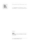
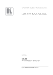
910
Digital Audio Preamplifier
Contents
Contents
1
2
2.1
3
4
5
6
6.1
6.2
Introduction
Getting Started
Quick Start
Overview
Your 910 Digital Audio Preamplifier
Installing the 910 in a Rack
Connecting the 910 Digital Audio Preamplifier
Connecting the RS-232 Port
Connecting the ETHERNET Port
1
1
2
3
3
7
8
9
9
6.2.1
6.2.2
6.2.3
Connecting the ETHERNET Port Directly to a PC (Crossover Cable)
10
Connecting the ETHERNET Port via a Network Hub (Straight Through Cable) 11
Configuring the Ethernet Port
11
6.3
6.4
7
7.1
Connecting via USB
Connecting a Microphone to the XLR Input
Operating the 910 Digital Audio Preamplifier
Using the Front Panel Buttons
13
13
14
14
7.1.1
7.1.2
7.1.3
7.1.4
7.1.5
Using MIX
Using Loudness
Using Talkover
Using Store
Using Recall
14
14
14
14
14
7.2
7.3
7.4
8
9
9.1
Controlling the 910 from the PC
Using the Infrared Remote Controller
Updating the 910 Firmware
Technical Specifications
Protocol 3000 Syntax
Host Message Format
16
16
16
17
18
18
9.1.1
9.1.2
Simple Command
Command String
18
18
9.2
Device Message Format
18
9.2.1
Device Long Response
18
10
10.1
10.2
10.3
10.4
10.5
10.6
910 Commands in Protocol 3000
Help Commands
Device Initiated Messages
Result and Error Codes
Basic Routing Commands
Preset Commands
Audio Parameter Commands
19
19
19
19
20
20
21
i
Contents
10.7
10.8
10.9
10.10
10.11
10.12
10.13
10.14
10.15
Identification Commands
Network Setting Commands
Machine Information Commands
Command Terms
Entering Commands
Command Forms
Command Chaining
Maximum String Length
Backward Support
22
22
23
23
24
24
24
25
25
Figures
Figure 1: 910 Digital Audio Preamplifier
Figure 2: Connecting the 910 Digital Audio Preamplifier
Figure 3: Local Area Connection Properties Window
Figure 4: Internet Protocol (TCP/IP) Properties Window
Figure 5: Connect Screen
Figure 6: Device Properties Screen
Figure 7: Connecting a Microphone to the XLR Input
Figure 8: 910 Control Application Screen
4
9
10
11
12
13
13
16
Tables
Table 1: 910 Digital Audio Preamplifier Functions
Table 2: 910 Front Panel Button Functions
Table 3: 910 Technical Specifications
ii
5
15
17
KRAMER: SIMPLE CREATIVE TECHNOLOGY
Introduction
1
Introduction
Welcome to Kramer Electronics! Since 1981, Kramer Electronics has been
providing a world of unique, creative, and affordable solutions to the vast
range of problems that confront the video, audio, presentation, and
broadcasting professional on a daily basis. In recent years, we have
redesigned and upgraded most of our line, making the best even better! Our
1,000-plus different models now appear in 11 groups 1 that are clearly
defined by function.
Thank you for purchasing the Kramer 910 Digital Audio Preamplifier,
which is ideal for:
• Professional audio applications
• Sound studios
• Boardrooms and classrooms
• Training applications
Each package includes the following items:
• The 910 Digital Audio Preamplifier
• Power cord 2
• RC-IR2 remote control transmitter
• Windows®-based Kramer control software
• This user manual 3
2
Getting Started
We recommend that you:
• Unpack the equipment carefully and save the original box and
packaging materials for possible future shipment
• Review the contents of this user manual
• Use Kramer high-performance high-resolution cables 4
1 GROUP 1: Distribution Amplifiers; GROUP 2: Switchers and Matrix Switchers; GROUP 3: Control Systems;
GROUP 4: Format/Standards Converters; GROUP 5: Range Extenders and Repeaters; GROUP 6: Specialty AV Products;
GROUP 7: Scan Converters and Scalers; GROUP 8: Cables and Connectors; GROUP 9: Room Connectivity;
GROUP 10: Accessories and Rack Adapters; GROUP 11: Sierra Products
2 We recommend that you use only the power cord supplied with this device
3 Download up-to-date Kramer user manuals from http://www kramerelectronics com
4 The complete list of Kramer cables is available from http://www kramerelectronics com
1
Getting Started
2.1
Quick Start
This quick start chart summarizes the basic setup and operation steps.
2
KRAMER: SIMPLE CREATIVE TECHNOLOGY
Overview
3
Overview
The 910 is a high-performance stereo audio preamplifier. It accepts
balanced and unbalanced stereo audio, S/PDIF digital audio, and
microphone inputs, processes the signals, and outputs them to balanced,
unbalanced and S/PDIF outputs.
The 910 has the following features:
• Grouped audio controls: volume, balance, bass, mid, treble,
loudness, equalizer, delay, mute, expand and compress
• Selectable condenser or dynamic mic input with talk over, mix and
override controls
• A 24-character by 2-line LCD display
• Memory locations that store up to 4 presets to be recalled and
executed when needed
• A USB port for software upgrades
• Flexible control options including the front panel, RS-232 (with
Windows®-based control software included), Ethernet and IR
• Standard 19” rack mount size of 1U with rack "ears" included
To achieve the best performance:
• Use only good quality connection cables 1 to avoid interference,
deterioration in signal quality due to poor matching, and elevated
noise levels (often associated with low quality cables).
• Avoid interference from neighboring electrical appliances that may
adversely influence signal quality and position your Kramer 910
away from moisture, excessive sunlight and dust
4
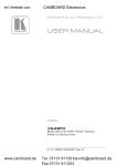
Your 910 Digital Audio Preamplifier
Figure 1 and Table 1 define the unit.
1 Available from Kramer Electronics on our Web site at http://www kramerelectronics com
3
Your 910 Digital Audio Preamplifier
Figure 1: 910 Digital Audio Preamplifier
4
KRAMER: SIMPLE CREATIVE TECHNOLOGY
Your 910 Digital Audio Preamplifier
Table 1: 910 Digital Audio Preamplifier Functions
#
Feature
1
IR Receiver
2
MUTE Button
3
4
5
6
7
8
INPUT Selector Buttons
MID Button
BASS Button
TREBLE Button
LOUDNESS Button
EQUALIZER Button
9
VOLUME Button
10
BALANCE Button
11
12
13
DELAY Button
MIX Button
TALKOVER Button
14
15
16
EXPAND Button
COMPRESS Button
STORE Button
17
RECALL Button
18
19
20
DISPLAY
Adjustment Knob
INPUT 1 (LEFT, RIGHT) RCA
Connectors
INPUT 2 Terminal Block
Connector
INPUT 3 S/PDIF RCA
Connector
INPUT 4 MIC XLR Connector
21
22
23
24
25
26
27
28
MIC MODE (DYN/COND )
Pushbutton
OUTPUT 1 (LEFT, RIGHT)
RCA Connectors
OUTPUT 2 Terminal Block
Connector
OUTPUT 3 S/PDIF RCA
Connector
PROGRAM Switch
Function
The red LED illuminates when receiving signals from the infrared
remote control transmitter
Press to toggle between turning off (muting) and turning on the
audio output
Press a button to select an input (1 to 4)
Press to adjust midrange frequencies on the selected input
Press to adjust low frequencies on the selected input
Press to adjust high frequencies on the selected input
Press to toggle loudness on the selected input
Press to adjust 7 different frequency bands on the selected input;
each press advances to he next band
Press to adjust the output volume; to adjust the input volume
press VOLUME and STORE together
Press to change the relative volume between the left and right
channels on the selected input
Press to adjust the delay in milliseconds on the output
Press to choose multiple inputs
Press to allow the microphone to interrupt the selected input, the
background audio fades out when the microphone is loud enough
and fades in when the microphone is silent again
Press to increase the dynamic range of the output
Press to decrease the dynamic range of the output
Press to save the device settings; use the adjustment knob or the
input buttons to select the preset number
Press to bring back a stored preset, use the adjustment knob or
the input buttons to select the preset number
2 line, 24 character LCD display
Turn to adjust the value of the selected function
Connect to an unbalanced stereo audio source
Connect to a balanced stereo audio source
Connect to a digital audio source
Connect to a microphone. The XLR connector provides 15V
phantom power when the MIC switch is set for a condenser
microphone
Press IN for dynamic mic, set OUT for condenser mic
Connect to an unbalanced stereo audio acceptor (power
amplifier)
Connect to an balanced stereo audio acceptor (power amplifier)
Connect to a digital audio acceptor (digital power amplifier)
Slide down to upgrade the device firmware (see section 7.4); slide
up for normal operation
5
Your 910 Digital Audio Preamplifier
#
29
Feature
FACTORY DEFAULT Button
30
31
USB (PROGRAM) Connector
RS-232 9-pin D-sub (F) Port
32
ETHERNET RJ-45 Connector
33
34
Power Connector with Fuse
Power Switch
6
Function
Press to revert to the default settings, including all the configured
buttons
Connect to the PC using a USB cable for remote control
Connect to the RS-232 connector on the AV equipment or a PC or
other serial controller for remote control
Connects to the PC or o her serial controller through computer
networking LAN for remote control
AC connector enabling power supply to the 910
Illuminated switch for turning the unit ON and OFF
KRAMER: SIMPLE CREATIVE TECHNOLOGY
Installing the 910 in a Rack
5
Installing the 910 in a Rack
This section describes how to install the 910 in a rack.
7
Connecting the 910 Digital Audio Preamplifier
6
Connecting the 910 Digital Audio Preamplifier
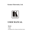
To connect the 910 as illustrated in the example in Figure 2 1:
1. Connect the inputs:
• Connect an unbalanced stereo source (for example, a tape
recorder) to the left and right INPUT 1 RCA connectors
• Connect an balanced stereo source (for example, a tape
recorder) to the left (L+, L-), right (R+, R-) and ground (G)
terminals on the INPUT 2 terminal block connectors
• Connect a digital audio source (for example, a digital audio
player) to the INPUT 3 S/PDIF RCA connector
• Connect a microphone to the INPUT 4 MIC XLR connector
(see Section 6.4). Set the MIC MODE button to Dynamic or
Condenser (pressed in)
2. Connect the outputs:
• Connect the left and right OUTPUT 1 RCA connectors to an
unbalanced stereo audio acceptor (for example, a power
amplifier)
• Connect left (L+, L-), right (R+, R-) and ground (G) terminals
on the OUTPUT 2 terminal block connectors to a balanced
stereo audio acceptor (for example, a power amplifier)
• Connect the OUTPUT 3 S/PDIF connector to a digital audio
acceptor (for example, a digital power amplifier)
3. To remotely operate the 910, make any of the following connections:
• RS-232 9-pin D-sub port to a PC (see Section 6.1)
• Ethernet RJ-45 connector to a network (see Section 6.2)
• USB connector to a PC (see Section 6.3)
4. Connect the power cord 2 (not shown in Figure 2).
1 Switch OFF the power on each device before connecting it to the 910 After connecting the 910, switch on its power and
then switch on the power on each device
2 We recommend that you use only the power cord supplied with this device
8
KRAMER: SIMPLE CREATIVE TECHNOLOGY
Connecting the 910 Digital Audio Preamplifier
Figure 2: Connecting the 910 Digital Audio Preamplifier
6.1
Connecting the RS-232 Port
You can connect to the unit via a straight pin-to-pin RS-232 connection,
using for example, a PC.
Connect the RS-232 9-pin D-sub port on the unit via a straight cable (pin 2
to pin 2, Pin 3 to pin 3, and pin 5 to pin 5) to the RS-232 9-pin D-sub port
on the PC. Is a shielded cable is used, connect the shield to pin 5.
Note: There is no need to connect any other pins.
6.2
Connecting the ETHERNET Port
You can use the Ethernet port to control the 910.
• To connect directly to a PC using a crossover cable, see
Section 6.2.1
9
Connecting the 910 Digital Audio Preamplifier
• To connect to a network hub or network router with a straightthrough cable, see Section 6.2.2
• To configure the Ethernet port, see Section 6.2.3
6.2.1 Connecting the ETHERNET Port Directly to a PC (Crossover
Cable)
You can connect the Ethernet port of the 910 to the Ethernet port on your
PC, via a crossover cable with RJ-45 connectors.
This type of connection is recommended for identification of the factory default
IP Address of the 910 during the initial configuration
After connecting the Ethernet port, configure your PC as follows:
1. Right-click the My Network Places icon on your desktop.
2. Select Properties.
3. Right-click Local Area Connection Properties.
4. Select Properties.
The Local Area Connection Properties window appears.
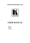
5. Select the Internet Protocol (TCP/IP) and click the Properties Button (see
Figure 3).
Figure 3: Local Area Connection Properties Window
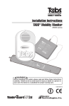
6. Select Use the following IP address, and fill in the details as shown in
Figure 4.
10
KRAMER: SIMPLE CREATIVE TECHNOLOGY
Connecting the 910 Digital Audio Preamplifier
7. Click OK.
Figure 4: Internet Protocol (TCP/IP) Properties Window
6.2.2 Connecting the ETHERNET Port via a Network Hub (Straight
Through Cable)
You can connect the Ethernet port of the 910 to the Ethernet port on a
network hub or network router, via a straight through cable with RJ-45
connectors.
6.2.3 Configuring the Ethernet Port
To configure the Ethernet port, download the P3K configuration software 1.
Extract the file to a folder and create a shortcut on your desktop to the file.
Follow these steps to configure the port:
1. Double click the desktop icon.
The Connect screen appears as follows:
1 Available from Kramer Electronics on our Web site at http://www kramerelectronics com
11
Connecting the 910 Digital Audio Preamplifier
Figure 5: Connect Screen
2. Select the method to connect to the Ethernet port of the 910.
Select:
• Ethernet, if you know the IP address number 1 or the machine
name. The default name for the machine is
KRAMER_XXXX 2
• Serial, if you are connected via a serial port
3. Click OK.
The Device Properties window appears:
1 The default IP address is 192 168 1 39
2 The four digits are the last four digits of the machine’s serial number
12
KRAMER: SIMPLE CREATIVE TECHNOLOGY
Connecting the 910 Digital Audio Preamplifier
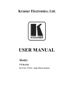
Figure 6: Device Properties Screen
4. If required, make changes and press Set. If not, click Close.
6.3
Connecting via USB
To connect the 910 via the USB port, you must plug the USB cable into the
PC and install the Kramer USB driver downloaded from our Web site at
http://www kramerelectronics.com.
6.4
Connecting a Microphone to the XLR Input
Connect a microphone to the XLR input as illustrated in Figure 7.
Figure 7: Connecting a Microphone to the XLR Input
Note: The XLR connector provides 15V phantom power when the MIC
switch is set for a condenser microphone.
13
Operating the 910 Digital Audio Preamplifier
7
Operating the 910 Digital Audio Preamplifier
You can operate your 910 using:
• The front panel buttons (see Section 7.1)
• Serial commands via the RS-232/USB/Ethernet ports transmitted
by a touch screen system, PC, or other serial controller (see
Section 7.2)
• RC-IR2 Infrared remote control transmitter (see Section 7.3)
7.1
Using the Front Panel Buttons
The 910 is operated from its front panel buttons as follows (for an
explanation of the front panel button functions see Table 2):
1. Select an input from 1 to 4 by pressing its INPUT button.
The selected input appears in the display.
2. Select a function by pressing its appropriate button.
The selected input and function appear in the display.
3. Adjust the function using the adjustment knob.
7.1.1 Using MIX
To mix multiple inputs (any or all) press the MIX button and press any
INPUT desired. Each selected input lights.
7.1.2 Using Loudness
Pressing LOUDNESS activates and deactivates the loudness function.
7.1.3 Using Talkover
To use the talkover function, press TALKOVER. The microphone on
INPUT 4 activates. The audio fades out when the microphone input is loud
enough and fades back in when the microphone is silent for approximately
1.5 seconds.
7.1.4 Using Store
Up to four current settings can be stored in four presets. To store a preset:
press STORE, it flashes. Choose a preset location by turning the adjustment
knob or pressing an INPUT button. Press STORE again to save the preset.
7.1.5 Using Recall
To recall any of the four presets: press RECALL, it flashes. Choose a preset
location by turning the adjustment knob or pressing an INPUT button. Press
RECALL to activate the preset.
14
KRAMER: SIMPLE CREATIVE TECHNOLOGY
Operating the 910 Digital Audio Preamplifier
Table 2: 910 Front Panel Button Functions
Button Display
MUTE
1
4
BASS
TREB
MID
LDNS
VOL
BAL
EQ
DLY
TR
EXPD
MIX
CMPS
STO
Meaning/Range
Mute
2
3
Function
Notes
When pressed, stops all output
INPUT 1
Unbalanced stereo
INPUT 2
Balanced stereo
INPUT 3
S/PDIF digital stereo
INPUT 4
Microphone
Bass
-40 to +40
Adjusts low-level tones
Treble
-40 to +40
Adjusts high-level tones
Mid
-40 to +40
Adjusts mid-level tones
Loudness
-40 to +40
Toggles loudness on and off
Volume
-100 to +24
Adjusts output volume
Balance
-24 to +24
Adjusts right and left volume
Equaliza ion
Equalizes 7 bands from low to high
-40 to +40 each band frequency; each press advances to the
next band
Delay
0 to 60
Only one input lights when selected,
multiple buttons light when MIX pressed
Delay in milliseconds to avoid feedback
from the microphone
Talkover
Ac ivates INPUT 4 (mic) and lowers all
other inputs to the background
Expand
Increases the dynamic range of the
output by a fixed ra io
Mix
Allows multiple inputs
Compress
Decreases the dynamic range of the
output by a fixed ra io
Store
Stores four presets: press STORE, adjust
for preset number, press STORE
Recall
Recalls four presets: press RECALL,
adjust for preset number, press RECALL
RCL
15
Operating the 910 Digital Audio Preamplifier
7.2
Controlling the 910 from the PC
To operate your device remotely from your PC over the RS-232, USB or
Ethernet ports, you need to download and install Kramer's 910 Control
Application 1.
Figure 8: 910 Control Application Screen
For an explanation of all control commands, see Section 10.
7.3
Using the Infrared Remote Controller
To operate your device using the RC-IR2 infrared remote controller, see the
User Manual packed with the remote controller.
7.4
Updating the 910 Firmware
The 910 functions by means of a device microcontroller that runs firmware
located in FLASH memory.
You can download1 and upgrade the latest version of firmware 2 according
to the recommendation of Kramer Technical Support.
1 Available on our Web site at http://www kramerelectronics com
2 The firmware is installed using the P3K software available from the Kramer Web site http://www kramerelectronics com
16
KRAMER: SIMPLE CREATIVE TECHNOLOGY
Technical Specifications
8
Technical Specifications
The 910 technical specifications are shown in Table 3:
Table 3: 910 Technical Specifications
INPUTS:
OUTPUTS:
OUTPUT LEVEL:
BANDWIDTH (-3dB):
S/N RATIO:
CONTROLS:
VOLTAGE GAIN:
COUPLING:
AUDIO THD + NOISE:
AUDIO 2nd HARMONIC:
POWER SOURCE:
DIMENSIONS
WEIGHT:
ACCESSORIES:
1
1 unbalanced stereo audio on an RCA connector;
1 balanced stereo audio on a 5-pin terminal block;
1 S/PDIF on an RCA connector;
1 mono balanced microphone on an XLR (F) connector (provides
15V phantom power when the MIC switch is set for a condenser
microphone)
1 unbalanced stereo audio on an RCA connector;
1 balanced stereo audio on a 5-pin terminal block;
1 S/PDIF on an RCA connector
8Vpp
21.7kHz
75dB @1kHz, weighted
Volume: <-75 to +23.5dB;
Bass: -15 to +15dB @100Hz;
Mid: -20 to +20dB @1kHz;
Treble: -10 to +10dB @20kHz;
Loudness: +10.6dB @50Hz, +4.3dB @1kHz, +6.8dB @20kHz;
Balance: <-64 to 0dB @1kHz;
Delay: 90usec to 300usec;
Expand: +23.8dB @1kHz;
Compress: -3.3dB @1kHz
22.5dB at max gain
AC
0.1% @1kHz
0.03% @1kHz
100-230V AC
19" x 7" x 1U (W, D, H)
2.0kg (4.4lbs)
Power cord, rack “ears”, IR remote control transmitter and
Windows®-based Kramer control software
1 Specifications are subject to change without notice
17
Protocol 3000 Syntax
9
Protocol 3000 Syntax
9.1
Host Message Format
Start
Address (optional)
Body
Delimiter
#
Destination_id@
Message
CR
9.1.1 Simple Command
Command string with only one command without addressing:
Start
Body
Delimiter
#
Command SP Parameter_1,Parameter_2,…
CR
9.1.2 Command String
Formal syntax with commands concatenation and addressing:
Start
Address
Body
Delimiter
#
Destination_id@
Command_1 Parameter1_1,Parameter1_2,…|
Command_2 Parameter2_1,Parameter2_2,…|
Command_3 Parameter3_1,Parameter3_2,…|…
CR
9.2
Start
~
Device Message Format
Address (optional)
Sender_id@
Body
Message
delimiter
CR LF
9.2.1 Device Long Response
Echoing command:
Start
Address (optional)
Body
Delimiter
~
Sender_id@
Command SP [Param1 ,Param2 …] result
CR LF
CR = Carriage return (ASCII 13 = 0x0D)
LF = Line feed (ASCII 10 = 0x0A)
SP = Space (ASCII 32 = 0x20)
18
KRAMER: SIMPLE CREATIVE TECHNOLOGY
910 Commands in Protocol 3000
10
910 Commands in Protocol 3000
This RS-232/RS-485 communication protocol lets you control the machine
from any standard terminal software (for example, Windows®
HyperTerminal Application) and uses a data rate of 115200 baud, with no
parity, 8 data bits, and 1 stop bit.
This section describes all commands sent to the 910. For an explanation of
the syntax and use of Protocol 3000, see Section 10.
10.1 Help Commands
Command
Syntax
Response
Protocol handshaking
#CR
~OKCRLF
10.2 Device Initiated Messages
Command
Syntax
Start message
Kramer Electronics LTD. , Device Model Version
Software Version
Switcher actions:
Audio channel has switched (breakaway mode)
AUD IN>OUT
10.3 Result and Error Codes
23B
Syntax
Command ran successfully, no error.
COMMAND PARAMETERS OK
Protocol Errors:
Syntax error
ERR001
Command not available for this device
ERR002
Parameter is out of range
ERR003
Unauthorized access (command run without the
matching login).
ERR004
19
910 Commands in Protocol 3000
10.4 Basic Routing Commands
Switch audio
AUD IN>OUT, IN>OUT, …
Short form: A IN>OUT, IN>OUT, …
AUD IN>OUT, IN>OUT, …RESULT
Read audio connec ion
AUD? OUT
Short form: A? OUT
AUD? *
AUD IN>OUT
AUD IN>1, IN>2, …
Parameter Description:
IN = Input number or '0' to disconnect output.
'>' = Connection character between in and out parameters.
OUT = Output number or '*' for all outputs.
Example:
Switch audio input 2 to output 1
#A 2>1CR
~AUD 2>1 OKCRLF
10.5 Preset Commands
Command
Syntax
Response
Store current connections to
preset
PRST-STO PRESET
Short form: PSTO PRESET
PRST-STO PRESET RESULT
Recall saved preset
PRST-RCL PRESET
Short form: PRCL PRESET
PRST-RCL PRESET RESULT
Delete saved preset
PRST-DEL PRESET
Short form: PDEL PRESET
PRST-DEL PRESET RESULT
Read audio connections from
saved preset
PRST-AUD? PRESET,OUT
Short form: PAUD? PRESET OUT
PRST-AUD? PRESET, *
PRST-AUD PRESET: IN>OUT
Read saved presets list
PRST-LST?
Short form: PLST?
PRST-LST PRESET, PRESET, …
PRST-AUD PRESET: IN>1, IN>2,…
Parameter Description:
PRESET = Preset number.
OUT = Output in preset to display, '*' for all.
Examples:
Store current audio connec ions #PRST-STR 5CR
to preset 5
~PRST-STR 5 OKCRLF
Recall audio connections from
preset 3
~PRST-RCL 3 OKCRLF
20
#PRCL 3CR
KRAMER: SIMPLE CREATIVE TECHNOLOGY
910 Commands in Protocol 3000
10.6 Audio Parameter Commands
Command
Syntax
Response
Set simple audio volume VOLUME VOLUME
Short form: VOL VOLUME
VOLUME VOLUME RESULT
Increase/decrease
simple audio volume
VOLUME +/Short form: VOL +/-
VOLUME +/- RESULT
Read simple audio level
VOLUME?
Short form: VOL?
VOLUME VOLUME
Set audio level in
specific amplifier stage.
AUD-LVL STAGE CHANNEL VOLUME
Short form: ADL STAGE CHANNEL VOLUME
AUD-LVL STAGE CHANNEL
VOLUME RESULT
Read audio volume level AUD-LVL? STAGE, CHANNEL
Short form: ADL? STAGE
AUD-LVL STAGE CHANNEL
VOLUME
Advanced commands for controlling each stage of audio amplification:
Set audio bass level
BASS BASS
Short form: ADB, BASS
BASS BASS RESULT
Read audio bass level
BASS?
Short form: ADB?
BASS BASS
Set audio treble level
TREBLE TREBLE
Short form: ADT TREBLE
TREBLE TREBLE RESULT
Read audio treble
TREBLE?
Short form: ADT?
TREBLE TREBLE
Set audio midrange
M DRANGE MID_RANGE
Short form: ADM M D_RANGE
MIDRANGE M D_RANGE RESULT
Read audio midrange
M DRANGE?
Short form: ADM?
MIDRANGE M D_RANGE
Set audio loudness
LOUDNESS LOUDNESS
Short form: ADS LOUDNESS
LOUDNESS LOUDNESS RESULT
Read audio loudness
LOUDNESS?
Short form: ADS?
LOUDNESS LOUDNESS
Set audio mix
MIX MIX-MODE
MIX MIX-MODE RESULT
Read audio mix
MIX?
MIX MIX-MODE
Mute audio
MUTE MUTE-MODE
MUTE MUTE-MODE RESULT
Read audio mute state
MUTE?
MUTE MUTE-MODE
Set balance mode
BALANCE BALANCE-LEVEL
BALANCE BALANCE-LEVEL RESULT
Read balance mode
BALANCE?
BALANCE BALANCE-LEVEL
Set equalizer
EQUALIZER BAND EQ_LEVEL
EQUALIZER BAND, EQ_LEVEL RESULT
Read equalizer
EQUALIZER? BAND
EQUALIZER BAND, EQ LEVEL
Set delay
DELAY DELAY_VOL
DELAY DELAY_VOL RESULT
Read delay
DELAY?
DELAY DELAY_VOL
Set talk over
TLK TALKOVER MODE
TLK TALKOVER MODE RESULT
Read talk over
TLK?
TLK TALKOVER_MODE
Set expand
EXPAND EXPAND_MODE
EXPAND EXPAND_MODE RESULT
Read expand
EXPAND?
EXPAND EXPAND_MODE
Set compress
COMPRESS COMPRESS_MODE
COMPRESS COMPRESS_MODE RESULT
Read compress
COMPRESS?
COMPRESS COMPRESS_MODE
21
910 Commands in Protocol 3000
Parameter Description:
STAGE = ‘IN, ’OUT’
or
Numeric value of present audio processing stage. For example: ‘0’ for input level, ‘1’ for pre-amplifier, ‘2’ for
amplifier (OUT) etc.
CHANNEL = Input or Output #
VOLUME / BASS / TREBLE / MID_RANGE = Audio parameter in Kramer units, minus sign precedes negative
values.
++ increase current value,
-- decrease current value.
MIX =
‘0’ or ‘OFF’
‘1’ or ‘ON’
TLK =
‘0’ or ‘OFF’
‘1’ or ‘ON’
EXPAND =
‘0’ or ‘OFF’
‘1’ or ‘ON’
COMPRESS =
‘0’ or ‘OFF’
‘1’ or ‘ON’
10.7 Identification Commands
Command
Syntax
Response
Protocol handshaking
#CR
~OK CRLF
Read device model
MODEL?
MODEL MACHINE_MODEL
Read device serial number
SN?
SN SERIAL_NUMBER
Read device firmware
version
VERSION?
VERSION MAJOR MINOR BUILD REVISION
Set machine name
NAME MACHINE_NAME
NAME MACHINE_NAME RESULT
Read machine name
NAME?
NAME MACHINE_NAME
Reset machine name to
factory default*
NAME-RST
NAME-RST MACHINE_FACTORY_NAME
RESULT
*Note: The machine name is not the same as the model name. The machine name is used to identify a specific
machine or a network in use (with DNS feature on).
MACHINE_NAME = Up to 14 alphameric chars.
* Machine factory name = Model name + last 4 digits from serial number.
10.8 Network Setting Commands
Command
Syntax
Response
Set IP address
NET-IP IP_ADDRESS
Short form: NTIP
NET-IP IP_ADDRESS RESULT
Read IP address
NET-IP?
Short form: NTIP?
NET-IP IP_ADDRESS
Read MAC address
NET-MAC?
Short form: NTMC
NET-MAC MAC_ADDRESS
Set subnet mask
NET-MASK SUBNET_MASK
Short form: NTMSK
NET-MASK SUBNET_MASK RESULT
Read subnet mask
NET-MASK?
Short form: NTMSK?
NET-MASK SUBNET_MASK
Set gateway address
NET-GATE GATEWAY_ADDRESS
Short form: NTGT
NET-GATE GATEWAY_ADDRESS
RESULT
Read subnet mask
NET-GATE?
Short form: NTGT?
NET-GATE GATEWAY_ADDRESS
22
KRAMER: SIMPLE CREATIVE TECHNOLOGY
910 Commands in Protocol 3000
Command
Syntax
Response
Set DHCP mode
NET-DHCP DHCP_MODE
Short form: NTDH
NET-DHCP?
Short form: NTDH?
NET-DHCP DHCP_MODE RESULT
Read subnet mask
NET-DHCP DHCP_MODE
DHCP_MODE =
‘0’ – Don't use DHCP (Use IP set by factory or IP set command).
‘1’ – Try to use DHCP, if unavailable use IP as above.
Change protocol
E hernet port
ETH-PORT PROTOCOL , PORT
Short form: ETHP
ETH-PORT PROTOCOL ,PORT RESULT
Read protocol
E hernet port
ETH-PORT? PROTOCOL
Short form: ETHP?
ETH-PORT PROTOCOL , PORT
PROTOCOL = TCP/UDP (transport layer protocol)
PORT = Ethernet port that accepts Protocol 3000 commands
1-65535 = User defined port
0 - Reset port to factory default (50000 for UDP, 5000 for TCP)
10.9 Machine Information Commands
Command
Syntax
Response
Set device time and date
TIME DATE_T ME
TIME DATE_T ME RESULT
Read device time and date
TIME?
TIME? DATE_TIME
Note: Time setting commands require administrator authoriza ion.
Read in/out count
INFO-IO?
INFO-IO: IN INPUTS_COUNT, OUT
OUTPUTS_COUNT
Read max preset count
INFO-PRST?
INFO-PRST: AUD PRESET_AUDIO_COUNT
Reset to factory default
configuration
FACTORY
FACTORY RESULT
10.10
Command Terms
Command
A sequence of ASCII letters ('A'-'Z', 'a'-'z' and '-').
Command and parameters must be separated by at least one space.
Parameters
A sequence of alphameric ASCII characters ('0'-'9','A'-'Z','a'-'z' and some
special characters for specific commands). Parameters are separated by
commas.
Message string
Every command entered as part of a message string begins with a message
starting character and ends with a message closing character.
Note: A string can contain more than one command. Commands are
separated by a pipe ( '|' ) character.
23
910 Commands in Protocol 3000
Message starting character
'#' – For host command/query
'~' – For machine response
Device address (Optional, for K-NET)
K-NET Device ID followed by '@'
Query sign
'?' follows some commands to define a query request.
All outputs sign
'*' defines all outputs.
Message closing character
CR – For host messages; carriage return (ASCII 13)
CRLF – For machine messages; carriage return (ASCII 13) + line-feed
(ASCII 10)
Command chain separator character
When a message string contains more then one command, a pipe ( '|' )
character separates each command.
Spaces between parameters or command terms are ignored.
10.11
Entering Commands
You can directly enter all commands using a terminal with ASCII
communications software, such as HyperTerminal, Hercules, etc. Connect
the terminal to the serial, Ethernet, or USB port on the Kramer device. To
enter CR , press the Enter key.
( LF is also sent but is ignored by command parser).
For commands sent from some non-Kramer controllers like Crestron, some
characters require special coding (such as, /X##). Refer to the controller
manual.
10.12
Command Forms
Some commands have short name syntax in addition to long name syntax to
allow faster typing. The response is always in long syntax.
10.13
Command Chaining
Multiple commands can be chained in the same string. Each command is
delimited by a pipe character ( '|' ). When chaining commands, enter the
message starting character and the message closing character only once,
at the beginning of the string and at the end.
24
KRAMER: SIMPLE CREATIVE TECHNOLOGY
910 Commands in Protocol 3000
Commands in the string do not execute until the closing character is
entered.
A separate response is sent for every command in the chain.
10.14
Maximum String Length
64 characters
10.15
Backward Support
Protocol 2000 is transparently supported by Protocol 3000. You can switch
between protocols using a switch protocol command from either platform.
25
LIMITED WARRANTY
Kramer Electronics (hereafter Kramer) warrants this product free from defects in material and workmanship under the
following terms
HOW LONG IS THE WARRANTY
Labor and parts are warranted for seven years from the date of the first customer purchase
WHO IS PROTECTED?
Only the first purchase customer may enforce this warranty
WHAT IS COVERED AND WHAT IS NOT COVERED
Except as below, this warranty covers all defects in material or workmanship in this product The following are not covered
by the warranty:
1 Any product which is not distributed by Kramer, or which is not purchased from an authorized Kramer dealer If you are
uncertain as to whether a dealer is authorized, please contact Kramer at one of the agents listed in the Web site
www kramerelectronics com
2 Any product, on which the serial number has been defaced, modified or removed, or on which the WARRANTY VOID
IF TAMPERED sticker has been torn, reattached, removed or otherwise interfered with
3 Damage, deterioration or malfunction resulting from:
i) Accident, misuse, abuse, neglect, fire, water, lightning or other acts of nature
ii) Product modification, or failure to follow instructions supplied with the product
iii) Repair or attempted repair by anyone not authorized by Kramer
iv) Any shipment of the product (claims must be presented to the carrier)
v) Removal or installation of the product
vi) Any other cause, which does not relate to a product defect
vii) Cartons, equipment enclosures, cables or accessories used in conjunction with the product
WHAT WE WILL PAY FOR AND WHAT WE WILL NOT PAY FOR
We will pay labor and material expenses for covered items We will not pay for the following:
1 Removal or installations charges
2 Costs of initial technical adjustments (set-up), including adjustment of user controls or programming These costs are the
responsibility of the Kramer dealer from whom the product was purchased
3 Shipping charges
HOW YOU CAN GET WARRANTY SERVICE
1
2
3
To obtain service on you product, you must take or ship it prepaid to any authorized Kramer service center
Whenever warranty service is required, the original dated invoice (or a copy) must be presented as proof of warranty
coverage, and should be included in any shipment of the product Please also include in any mailing a contact name,
company, address, and a description of the problem(s)
For the name of the nearest Kramer authorized service center, consult your authorized dealer
LIMITATION OF IMPLIED WARRANTIES
All implied warranties, including warranties of merchantability and fitness for a particular purpose, are limited in duration to
the length of this warranty
EXCLUSION OF DAMAGES
The liability of Kramer for any effective products is limited to the repair or replacement of the product at our option Kramer shall
not be liable for:
1 Damage to other property caused by defects in this product, damages based upon inconvenience, loss of use of the product, loss
of time, commercial loss; or:
2 Any other damages, whether incidental, consequential or otherwise Some countries may not allow limitations on how long an
implied warranty lasts and/or do not allow the exclusion or limitation of incidental or consequential damages, so the above
limitations and exclusions may not apply to you
This warranty gives you specific legal rights, and you may also have other rights, which vary from place to place
NOTE: All products returned to Kramer for service must have prior approval This may be obtained from your dealer
This equipment has been tested to determine compliance with the requirements of:
EN-50081:
EN-50082:
CFR-47:
"Electromagnetic compatibility (EMC);
generic emission standard
Part 1: Residential, commercial and light industry"
"Electromagnetic compatibility (EMC) generic immunity standard
Part 1: Residential, commercial and light industry environment"
FCC* Rules and Regulations:
Part 15: “Radio frequency devices
Subpart B Unintentional radiators”
CAUTION!
Servicing the machines can only be done by an authorized Kramer technician Any user who makes changes or
modifications to the unit without the expressed approval of the manufacturer will void user authority to operate the
equipment
Use the supplied DC power supply to feed power to the machine
Please use recommended interconnection cables to connect the machine to other components
* FCC and CE approved using STP cable (for twisted pair products)
26
For the latest information on our products and a list of
Kramer distributors visit www.kramerelectronics.com
where updates to this user manual may be found.
We welcome your questions, comments and feedback.
Safety Warning:
Disconnect the unit from the power supply before
opening/servicing.
Caution
Kramer Electronics, Ltd.
Web site: www kramerelectronics.com
E-mail: [email protected]
P/N: 2900-000492 REV 3