1
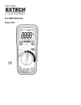
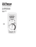
USER GUIDE Automotive Multimeter MODEL AUT500 Introduction Thank you for selecting the Extech AUT500 Automotive Multimeter. The AUT500 is an Auto Range Multimeter that measures AC/DC Voltage, AC/DC Current, Resistance, Capacitance, Frequency, Diode, Continuity, RPM, Dwell, and Duty Cycle. The AUT500 also measures contact temperature via supplied Thermocouple probe. The AUT500 features a rugged design for heavy duty use. This device is shipped fully tested and calibrated and, with proper use, will provide years of reliable service. Please visit our website (www.extech.com) to check for the latest version of this User Guide, Product Updates, and Customer Support. Safety International Safety Symbols This symbol, adjacent to another symbol or terminal, indicates the user must refer to the manual for further information. This symbol, adjacent to a terminal, indicates that, under normal use, hazardous voltages may be present Double insulation WARNING This WARNING symbol indicates a potentially hazardous situation, which if not avoided, could result in death or serious injury. CAUTION This CAUTION symbol indicates a potentially hazardous situation, which if not avoided, may result damage to the product. MAX 600V This symbol advises the user that the terminal(s) so marked must not be connected to a circuit point at which the voltage with respect to earth ground exceeds (in this case) 600 VAC or VDC. CAUTIONS Improper use of this meter can cause damage, shock, injury or death. Read and understand this user manual before operating the meter. Always remove the test leads before replacing the battery or fuses. Inspect the condition of the test leads and the meter itself for any damage before operating the meter. Repair any damage or replace the unit before use. Use great care when making measurements if the voltages are greater than 25VAC rms or 35VDC. These voltages are considered a shock hazard. Always discharge capacitors and remove power from the device under test before performing Diode, Resistance or Continuity tests. Voltage checks on electrical outlets can be difficult and misleading because of the uncertainty of connection to the recessed electrical contacts. Other means should be used to ensure that the terminals are not "live". 2 AUT500-EU-EN v1.0 5/13 If the equipment is used in a manner not specified by the manufacturer, the protection provided by the equipment may be impaired. This device is not a toy and must not reach children’s hands. It contains hazardous objects as well as small parts that the children could swallow. In case a child swallows any of them, please contact a physician immediately Do not leave batteries and packing material lying around unattended; they can be dangerous for children if they use them as toys In case the device is going to be unused for an extended period of time, remove the batteries to prevent them from training Expired or damaged batteries can cause cauterization on contact with the skin. Always, therefore, use suitable hand gloves in such cases See that the batteries are not short-circuited. Do not throw batteries into the fire. DANGERS Engines produce carbon monoxide which is odorless, causes slower reaction time, and can lead to serious injury. When the engine is operating keep service areas well ventilated or attach the vehicle exhaust system to the shop exhaust removal system. Set the parking brake and block the wheels before testing or repairing the vehicle. It is especially important to block the wheels on front-wheel drive vehicles; the parking brake does not hold the drive wheels. Wear an eye shield when testing or repairing vehicles. Keep the meter away from spark plug and coil wires. Exceeding the limits of this meter is dangerous. This will expose you to serious or possibly fatal injury. Carefully read and understand the cautions and the specification limits of this meter. Avoid electrical shock; do not touch the test leads, tips, or the circuit under test. Do not try a voltage measurement with the test leads in the 20A or the mA terminal. Choose the proper range and function for the measurement. Do not try voltage or current measurements that may exceed the ratings marked on the Function/Range switch or terminal. When measuring current, connect the meter in series with the load. Never connect more than one set of test leads to the meter. Disconnect the live test lead before disconnecting the common test lead. The mA and the 20A terminals are protected by fuses. To avoid possible injury or damage, use only in circuits limited to 400mA. 3 AUT500-EU-EN v1.0 5/13 OVERVOLTAGE CATEGORY III This meter meets the IEC 610-1-2001 standard for OVERVOLTAGE CATEGORY III. Cat III meters are protected against overvoltage transients in fixed installation at the distribution level. Examples include switches in the fixed installation and some equipment for industrial use with permanent connection to the fixed installation. METER SAFETY RULES This meter has been designed for safe use, but must be operated with caution. The rules listed below must be carefully followed for safe operation. 1. NEVER apply voltage or current to the meter that exceeds the specified maximum: Input Protection Limits Function Maximum Input Voltage DC or V AC Ohms, Continuity Diode, Capacitance, Type K Temperature 600V AC or DC Frequency, % Duty, Pulse-ms, Dwell RPM mA AC/DC 400mA 250V 20A AC/DC 20A AC or DC* * 20A measurements for 30 seconds maximum Notes: Resistance (Ohms) cannot be measured if voltage is present. Resistance can only be measured on a non-powered circuit 2. 3. 4. 5. 6. 7. USE EXTREME CAUTION when working with high voltages. DO NOT measure voltage if the voltage on the "COM" input jack exceeds 600V above earth ground. NEVER connect the meter leads across a voltage source while the function switch is in the current, resistance, or diode mode. Doing so can damage the meter. ALWAYS discharge filter capacitors in power supplies and disconnect the power when making resistance or diode tests. ALWAYS turn off the power and disconnect the test leads before opening the covers to replace the fuse or batteries. NEVER operate the meter unless the back cover and the battery and fuse covers are in place and fastened securely. 4 AUT500-EU-EN v1.0 5/13 Controls and Jacks 1. 2. 3. 4. 5. 6. 7. 8. 9. 10. 11. 12. LCD display MODE button HOLD button RANGE button PEAK button MAX-MIN button Backlight button Function switch 20A input jack 400mA input jack Positive input jack COM input jack Note: Tilt stand, test lead holders, and battery compartment are located on rear of unit. Fuses are accessible by removing the meter’s back cover, instructions provided later in this guide. 5 AUT500-EU-EN v1.0 5/13 Symbols and Annunciators •))) Continuity Diode test Battery status -9 n nano (10 ) (capacitance) µ micro (10 ) (amps, cap) -6 -3 m milli (10 ) (volts, amps, milli-seconds: ms) A Amps k kilo (10 ) (ohms) 3 F Farads (capacitance) M mega (10 ) (ohms) 6 Ohms (resistance, continuity) Hz Hertz (frequency) V Volts % Percent REL Relative (unused in this model) AC Alternating current DC Direct current MAX Highest reading MIN Lowest reading ºF Degrees Fahrenheit ºC Degrees Centigrade Pmax Maximum peak Pmin Minimum peak RPM Rotations per minute Trig Positive (+) or Negative (-) Trigger CYL Cylinder (4, 5, 6, and 8) H x10 Display Hold Multiply displayed reading by 10 Bargraph Manual range (top left on LCD) AUTO Auto range mode Auto Power OFF icon (middle left on LCD) Dwell angle icon 6 AUT500-EU-EN v1.0 5/13 Operating Instructions WARNING: Risk of electrocution. High-voltage circuits, both AC and DC, are very dangerous and should be measured with great care. 1. ALWAYS turn the function switch to the OFF position when the meter is not in use. 2. If “OL” appears in the display during a measurement, the value exceeds the range selected. Change to a higher range. NOTE: On some low AC and DC voltage ranges, with the test leads not connected to a device, the display may show a random, changing reading. This response is normal and is caused by the highinput sensitivity. The reading will stabilize and give a proper measurement when connected to a circuit. DC VOLTAGE MEASUREMENTS CAUTION: Do not measure DC voltages if a motor on the circuit is being switched ON or OFF. Large voltage surges may occur that can damage the meter. 1. Set the function switch to the ‘V’ position. 2. Press the MODE button to indicate “DC” on the display. 3. Insert the black test lead banana plug into the negative COM jack. Insert the red test lead banana plug into the positive V jack. 4. Touch the black test probe tip to the negative side of the circuit. Touch the red test probe tip to the positive side of the circuit. 5. Read the voltage in the display as numerical digits and as bar-graph representation. 7 AUT500-EU-EN v1.0 5/13 AC VOLTAGE MEASUREMENTS WARNING: Risk of Electrocution. The probe tips may not be long enough to contact the live parts inside some 240V outlets for appliances because the contacts are recessed deep in the outlets. As a result, the reading may show 0 volts when the outlet actually has voltage on it. Make sure the probe tips are touching the metal contacts inside the outlet before assuming that no voltage is present. CAUTION: Do not measure AC voltages if a motor on the circuit is being switched ON or OFF. Large voltage surges may occur that can damage the meter. 1. Set the function switch to the ‘V’ position. 2. Press the MODE button to indicate “AC” on the display. 3. Insert the black test lead banana plug into the negative COM jack. Insert red test lead banana plug into the positive V jack. 4. Touch the black test probe tip to the neutral side of the circuit. Touch the red test probe tip to the “hot” side of the circuit. 5. Read the voltage in the display as numerical digits and as bar-graph representation. DC CURRENT MEASUREMENTS CAUTION: Do not make current measurements on the 20A scale for longer than 30 seconds. Exceeding 30 seconds may cause damage to the meter and/or the test leads. 1. Insert the black test lead banana plug into the negative COM jack. 2. For current measurements up to 400mA DC, set the function switch to the mA position and insert the red test lead banana plug into the 400mA jack. 3. For current measurements up to 20A DC, set the function switch to the 20A range and insert the red test lead banana plug into the 20A jack. 4. Press the MODE button to indicate “DC” on the display. 5. Remove power from the circuit under test, then open up the circuit at the point where you wish to measure current. 6. Touch the black test probe tip to the negative side of the circuit. Touch the red test probe tip to the positive side of the circuit. 7. Apply power to the circuit. 8. Read the current in the display as numerical digits and as bar-graph representation. 8 AUT500-EU-EN v1.0 5/13 AC CURRENT MEASUREMENTS CAUTION: Do not make current measurements on the 20A scale for longer than 30 seconds. Exceeding 30 seconds may cause damage to the meter and/or the test leads. 1. Insert the black test lead banana plug into the negative COM jack 2. For current measurements up to 400mA AC, set the function switch to the mA position and insert the red test lead banana plug into the 400mA jack. 3. For current measurements up to 20A AC, set the function switch to the 20A range and insert the red test lead banana plug into the 20A jack. 4. Press the MODE button to indicate “AC” on the display. 5. Remove power from the circuit under test, then open up the circuit at the point where you wish to measure current. 6. Touch the black test probe tip to the neutral side of the circuit. Touch the red test probe tip to the “hot” side of the circuit. 7. Apply power to the circuit. 8. Read the current in the display as numerical digits and as bar-graph representation. RESISTANCE MEASUREMENTS WARNING: To avoid electric shock, disconnect power to the unit under test and discharge all capacitors before taking any resistance measurements. Remove the batteries and unplug the line cords. 1. Set the function switch to the Ω position. 2. Insert the black test lead banana plug into the negative COM jack. Insert the red test lead banana plug into the positive jack. 3. Press the MODE button to indicate “"on the display. 4. Touch the test probe tips across the circuit or part under test. It is best to disconnect one side of the part under test so the rest of the circuit will not interfere with the resistance reading. 5. Read the resistance in the display. 9 AUT500-EU-EN v1.0 5/13 CONTINUITY CHECK WARNING: To avoid electric shock, never measure continuity on circuits or wires that have voltage on them. 1. Set the function switch to the Ω position. Refer to the Resistance measurement diagram above for reference. 2. Insert the black lead banana plug into the negative COM jack. Insert the red test lead banana plug into the positive jack. 3. Press the MODE button to indicate “ " on the display 4. Touch the test probe tips to the circuit or wire you wish to check. 5. If the resistance is less than approximately 35, the audible signal will sound. If the circuit is open, the display will indicate “OL”. DIODE TEST 1. Set the function switch to the Ω position. 2. Insert the black test lead banana plug into the negative COM jack and the red test lead banana plug into the positive V jack. 3. Press the MODE button to indicate display. and V on the 4. Touch the test probes to the diode under test. Forward voltage will typically indicate 0.400 to 0.700V. Reverse voltage will indicate “OL”. Shorted devices will indicate near 0V and an open device will indicate “OL” in both polarities. CONTACT TEMPERATURE MEASUREMENTS (TYPE K) 1. Set the function switch to the Type K ºC or ºF position. 2. Insert the Temperature Probe into the input jacks, making sure to observe the correct polarity. 3. Touch the Temperature Probe tip to the part under test. When the reading stabilizes (after approximately 30 seconds) remove the probe tip from the surface under test. 4. Read the temperature in the display as numerical digits and as bar-graph representation. Note: The temperature probe is fitted with a type K mini connector. A mini connector to banana connector adaptor is supplied for connection to the meter’s input banana jacks. 10 AUT500-EU-EN v1.0 5/13 CAPACITANCE MEASUREMENTS WARNING: To avoid electric shock, disconnect power to the unit under test and discharge all capacitors before taking any capacitance measurements. Remove the batteries and unplug the line cords. 1. Set the rotary function switch to the position. 2. Insert the black test lead banana plug into the negative (COM) jack. Insert the red test lead banana plug into the positive jack. 3. Touch the test leads to the capacitor to be tested. 4. Read the capacitance value in the display (note that the bar-graph is inactive in Capacitance mode). FREQUENCY MEASUREMENTS 1. Set the rotary function switch to the Hz position. 2. Insert the black lead banana plug into the negative COM jack and the red test lead banana plug into the positive Hz jack. 3. Touch the test probe tips to the circuit under test. 4. Read the frequency on the display. % DUTY CYCLE 1. Set the rotary function switch to the % position. 2. Insert the black lead banana plug into the negative COM jack and the red test lead banana plug into the positive % jack. 3. For Trigger options, press the RANGE key momentarily to select TRIG + or TRIG - in the display. 4. Touch the test probe tips to the circuit under test (black to ground and red to positive circuit point). 5. Read the % duty cycle on the display. A common automotive application for Duty Cycle is a Mixture Control Solenoid. The meter can display the percentage of time the solenoid’s plunger is in the closed position (low duty cycle) during one cycle. 11 AUT500-EU-EN v1.0 5/13 ms-PULSE (Pulse Width in milliseconds) Pulse width is the length of time an actuator is energized. For example, fuel injectors are activated by an electronic pulse from the Engine Control Module (ECM). The pulse generates a magnetic field that pulls the injector’s nozzle valve open. The pulse ends and the injector nozzle is closed. This ‘open to close’ time is the pulse width and it is measured in milliseconds (ms). The most common automotive application for measuring pulse width is fuel injection. The pulse width of the fuel mixture control solenoid and the idle air control motor can be measured. The next measurement section describes how to measure pulse width on port fuel injectors. PULSE WIDTH MEASUREMENT EXAMPLE 1. Set the rotary function switch to the ms-PULSE position. 2. Insert the black lead banana plug into the negative COM jack and the red test lead banana plug into the positive ms jack. 3. Press the RANGE key momentarily to select TRIG - in the display (the applied time for most fuel injectors is displayed on the negative slope). 4. Add a jumper cable between the fuel injector and the harness connector. 5. Connect the black test lead to a good ground at the fuel injector or the negative vehicle battery post. 6. Connect the red test lead to the fuel injector solenoid driver input on the jumper cable (from step 4). 7. Start the engine. 8. Read the pulse size in milliseconds on the display, Note: Initially the meter will read OL (over range) and then readings will descend and stabilize to the actual pulse width. If OL remains on the meter display, re-check the connections and test setup. DWELL MEASUREMENTS 1. Set the rotary function switch to the DWELL position. 2. Insert the black lead banana plug into the negative COM jack and the red test lead banana plug into the positive DWELL jack. 3. Touch the test leads to the breaker points’ wire (red test lead) and to a good ground (black test lead). 4. Select the number of engine cylinders (4, 5, 6, or 8) using the RANGE button. 5. Read dwell angle in degrees on the LCD. RPM MEASUREMENTS 1. Set the rotary function switch to the RPM or the x10 RPM position. Use the x10 position for readings 1000 to 12000 RPM. 2. Connect the supplied magnetic clamp pickup to the meter by inserting the black lead banana plug into the negative COM jack and the red test lead banana plug into the positive RPM jack. 3. Clamp the magnetic pickup around the spark plug wire to sense secondary ignition impulses. 4. Read the RPM on the display. When using the x10 mode, multiply the reading by a factor of 10. RPM Measurement notes: If no signal is detected, unclamp the pickup from the spark plug wire and re-clamp around the spark plug wire in the opposite direction. Position the pickup so it is 6 inches from the spark plug. If no signal is detected or if an erratic signal is detected try another spark plug wire. Position the magnetic pickup as far from the distributor and exhaust manifold as possible. AUT500-EU-EN v1.0 5/13 12 AUTORANGING/MANUAL RANGE SELECTION When the meter is first turned on, it automatically uses Auto Range mode. This automatically selects the best range for the measurements being made and is generally the best mode for most measurements. For measurement situations requiring that a range be manually selected, perform the following: symbol will appear 1. Press the RANGE key. The “AUTO” display indicator will turn off and the on the upper left hand corner of the LCD. 2. Now, momentary presses of the RANGE key steps through the available ranges until the desired range is selected. 3. To exit the Manual Range mode and return to the Auto Range mode, press and hold the RANGE key for 2 seconds. The circular Manual Range symbol will switch OFF and AUTO will reappear on the left side of the LCD. Note: Manual Range does not apply for the Capacitance, Frequency and Temperature functions. DISPLAY BACKLIGHT Press the backlight key momentarily to switch the backlight ON or OFF. Use the backlight feature sparingly to conserve battery energy. DISPLAY HOLD The hold function freezes the reading in the display. Press the HOLD key momentarily to activate or to exit the HOLD function. The ‘H” HOLD icon is visible when the meter is in the HOLD mode. PEAK HOLD The Peak Hold function captures the peaks (lowest and highest) up to 1 millisecond in duration for AC/DC Current or Voltage. 1. Press the PEAK button momentarily and the Pmax display icon will appear. The meter is now displaying captured peaks (highest). The display will only change when a higher peak is detected. 2. Press the PEAK button again and the Pmin display icon will appear. The meter is now capturing the lowest peaks. 3. Press and hold the PEAK button for 2 seconds to exit the Peak Hold mode. Pmax and Pmin icons should switch OFF. MAX-MIN MEMORY The meter can hold the higheset reading (MAX) and the lowest reading (MIN) encountered over the lenghth of any given measurement session. 4. Press the MAX-MIN momentarily the MAX indicator will appear. The meter is now showing the highest reading and will only update when a higher reading is sensed. 5. Press the MAX-MIN button again to view the lowest reading (MIN icon switches ON). 6. Press the MAX-MIN button again and the MAX-MIN icons will both switch ON and will be flashing on and off. The display is now showing real time measurements but is monitoring MAX and MIN readings in the background. To view MAX and MIN readings again, press the MAXMINI button again to view MAX and again to view MIN. 7. To exit the MAX-MIN mode press and hold the MAX-MIN button for 2 seconds. The MAX and MIN indicators will switch OFF. AUTO POWER OFF The Auto Power OFF utility will turn the meter off after 30 minutes of inactivity. LOW BATTERY INDICATION The icon indicates battery strength. Replace the batteries promptly when the battery symbol shows low battery capacity. 13 AUT500-EU-EN v1.0 5/13 Specifications Function DC Voltage AC Voltage DC Current AC Current Resistance Capacitance Temp (type-K) Range 400mV Resolution 0.1mV 4V 40V 400V 600V 0.001V 0.01V 0.1V 1V Accuracy (0.5% reading + 3 digits) (1.5% reading + 2 digits) (1.8% reading + 2 digits) 50 to 60Hz 400mV 0.1mV (1.5% reading + 5 digits) 4V 0.001V (1.0% reading + 3 digits) 40V 400V 600V 0.01V 0.1V 1V (1.5% reading + 3 digits) 400A 0.1A 4000A 40mA 400mA 4A 20A 50 to 60Hz 40mA 400mA 20A 400 1A 0.01mA 0.1mA 0.001A 0.01A 0.01mA 0.1mA 0.01A 0.1 (3.0% reading + 7 digits) (1.2% reading + 4 digits) 4k 0.001k (1.0% reading + 2 digits) 40k 0.01k 400k 0.1k 4M 0.001M 40M 4nF 0.01M 1pF (2.0% reading + 3 digits) 40nF 10pF (5.0% reading + 7 digits) 400nF 4F 0.1nF 1nF 40F 10nF 400F 4mF 40mF 0.1F 0.001mF 0.01mF -30 to 1000C 1C Pulse Width -22 to 1832F 1F 1.0 to 20.0ms 0.1ms Diode 1.0mA test; 1mV resolution Continuity Audible threshold: 35 (2.0% reading + 4 digits) (1.5% reading + 3 digits) (2.5% reading + 5 digits) (1.8% reading + 5 digits) (1.2% reading + 2 digits) (5.0% reading + 50 digits) (3.0% reading + 5 digits) (10.0% reading + 10 digits) (3.0% reading + 5C or 8F) (probe accuracy not included) (2.0% reading + 20 digits) (5.0% reading + 15 digits) Test Current: <1mA DC typical 14 AUT500-EU-EN v1.0 5/13 Function Frequency Range 4.000Hz 40.00Hz 400.0Hz 4.000MHz 40.00MHz Resolution 0.001Hz 0.01Hz 0.1Hz 0.001kHz 0.01kHz Accuracy (1.5% reading + 5 digits) (1.2% reading + 2 digits) Sensitivity: >5V RMS up to 40MHz and >15 VRMS over 40MHz Duty Cycle RPM 4 (tachometer) RPM 2/DIS DWELL ANGLE 0.1% (2.0% reading + 5 digits) Pulse width: 100µs to 100ms; Frequency: 5Hz to 100kHz; Sensitivity: >5V RMS 600 to 4000 RPM 1 RPM 1000 to 12000 x10 RPM 10 RPM (2.0% reading + 4 digits) 300 to 4000 RPM 1 RPM 1000 to 6000 x10 RPM 10 RPM Effective Reading >600V o 4 CYL 0 to 90.0 o 5 CYL 0 to 72.0 o 0.1 (2.0% reading + 4 digits) o 6 CYL 0 to 60.0 o 8 CYL 0 to 45.0 0.5 to 99.9% NOTES: o o o o Accuracy is stated at 18 C to 28 C (65 F to 83 F) and less than 75% RH Accuracy specifications consist of two elements: (% reading) – This is the accuracy of the measurement circuit. (+ digits) – This is the accuracy of the analog to digital converter. 15 AUT500-EU-EN v1.0 5/13 GENERAL SPECIFICATIONS Compliance IEC 1010-1 EN61010-1 Insulation Class 2, Double Insulation Overvoltage CAT III 1000V, CAT IV 600V Display 4000 count LCD with multifunction indicators Polarity Automatic, (-) negative polarity Over-range ‘OL’ display Measurement rate 2 readings per second Diode Test Test current of 1mA typical; open circuit voltage 3V DC typical Continuity Check Audible signal will sound if the resistance is less than 35 Temperature Sensor Type K thermocouple with mini-jack and banana jack adaptor (supplied) Fuses 400mA range; 0.5A/250V fast blow 20A range; 20A/250V ceramic fast blow Power One (1) 9V battery (NEDA 1604) Low Battery Indication Battery symbol indicates battery power status Auto Power OFF Meter switches OFF after 30 minutes of inactivity Operating conditions 0ºC to 50ºC (32ºF to 122ºF); <70% RH Storage conditions -20ºC to 60ºC (-4ºF to 60ºF); <80% RH Indoor use only 2000m (7000ft) elevation maximum Pollution degree 2 Dimensions 182 x 82 x 55mm (7.2 x 3.2 x 2.2”) Weight 375g (13.2 oz.) 16 AUT500-EU-EN v1.0 5/13 Maintenance WARNING: To avoid electrical shock, disconnect the meter from any circuit, remove the test leads from the input terminals, and turn OFF the meter before opening the case. Do not operate the meter with an open case. This instrument is designed to provide years of dependable service, if the following care instructions are performed: 1. KEEP THE METER DRY. If it gets wet, wipe it off. 2. USE AND STORE THE METER IN NORMAL TEMPERATURES. Temperature extremes can shorten the life of the electronic parts and distort or melt plastic parts. 3. HANDLE THE METER GENTLY AND CAREFULLY. Dropping it can damage the electronic parts or the case. 4. KEEP THE METER CLEAN. Wipe the case occasionally with a damp cloth. DO NOT use chemicals, cleaning solvents, or detergents. 5. USE ONLY FRESH BATTERIES OF THE RECOMMENDED SIZE AND TYPE. Remove old or weak batteries so they do not leak and damage the unit. 6. IF THE METER IS TO BE STORED FOR A LONG PERIOD OF TIME, the batteries should be removed to prevent damage to the unit. BATTERY REPLACEMENT 1. Remove the Phillips head screw at the center (back) of the meter that secures the rear battery compartment door. 2. Open the battery compartment 3. Replace the 9V battery 4. Secure the battery compartment You, as the end user, are legally bound (EU Battery ordinance) to return all used batteries, disposal in the household garbage is prohibited! You can hand over your used batteries / accumulators at collection points in your community or wherever batteries / accumulators are sold! Disposal: Follow the valid legal stipulations in respect of the disposal of the device at the end of its lifecycle WARNING: To avoid electric shock, do not operate the meter until the battery cover is in place and fastened securely. NOTE: If the meter does not work properly, check the fuses and batteries to make sure that they are still good and that they are properly inserted. 17 AUT500-EU-EN v1.0 5/13 REPLACING THE FUSES WARNING: To avoid electrical shock, disconnect the meter from any circuit, remove the test leads from the input terminals, and turn OFF the meter before opening the case. Do not operate the meter with an open case. 1. Disconnect the test leads from the meter and from any device under test. 2. Remove the four Phillips screws on the rear of the meter (2 at the top edges and two at the middle edges of the meter). 3. Gently pull the meter’s rear cover off of the meter to access the fuses. 4. Gently remove the old fuse from its holder and install the new fuse into the same holder. 5. Always use a fuse of the proper size and value (0.5A/250V fast blow for the 400mA range, 20A/250V fast blow for the 20A range). 6. Re-assemble the meter by replacing and secure the rear cover with the screws. WARNING: To avoid electric shock, do not operate the meter until the fuse cover is in place and fastened securely. Copyright © 2013 FLIR Systems, Inc. All rights reserved including the right of reproduction in whole or in part in any form ISO-9001 Certified www.extech.com 18 AUT500-EU-EN v1.0 5/13