1
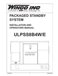
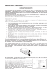
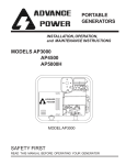
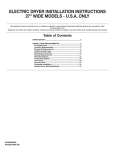
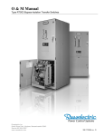
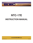
PACKAGED STANDBY SYSTEM INSTALLATION AND OPERATORS MANUAL ULPSS15B4W/E 11080-00 1 60706-206 SAVE THESE INSTRUCTIONS PROPER USE AND INSTALLATION This manual contains important instructions that should be followed during installation and maintenance of the generator and battery. Read and understand all instructions in the manual before starting and operating the generator set. You must be sure your new engine generator set is: * Properly serviced before starting. * Operated in a well ventilated area. * Properly exhausted and gases safely dispersed. * Wired by a qualified electrician. * Operated only for its designed purposes. * Used only by operators who understand its operation. * Properly maintained. USING THE MANUAL Congratulations on your choice of a Winco generator set. You have selected a high-quality, precision engineered generator set designed and tested to give you years of satisfactory service. To get the best performance from your new engine generator set, it is important that you carefully read and follow the operating instructions in this manual. COPY YOUR MODEL AND SERIAL NUMBER HERE Should you experience a problem please follow the “Troubleshooting Tables” near the end of this manual. The warranty listed in the manual describes what you can expect from WINCO should you need service assistance in the future. No other WINCO generator has the same serial number as yours. It is important that you record the number and other vital information here. If you should ever need to contact us on this unit it will help us to respond to your needs faster. TABLE OF CONTENTS INTRODUCTION GUIDE TO PRODUCT SAFETY BASIC INFORMATION Description Specifications PREPARING THE UNIT Unpacking the Unit ENGINE GENERATOR INSTALLATION Installation Fuel Installation Vapor Fuel Pressure Tables Fuel Conversions Battery Installation Connecting Battery Charger TRANSFER SWITCH INSTALLATION AC Electrical Connections DC Electrical Connections PREVENTIVE MAINTENANCE TROUBLESHOOTING INFORMATION WIRING DIAGRAMS AC & DC Generator Schematics UL ATS Wiring Diagram GENERATOR SET OUTLINE GENERATOR SET PAD LAYOUT GENERATOR WINDING DATA 12 MONTH WARRANTY MAINTENANCE LOG 11080-00 MODEL__________________________________ 2 3 SERIAL NUMBER_________________________ 4 5 PURCHASE DATE_________________________ 5 DEALER_________________________________ 5 6 7 8 9 11 DEALER PHONE # ________________________ 11 13 16 17 18 19 20 21 22 23 24 2 60706-206 SAFETY INFORMATION 2. FIRE HAZARD Natural gas, and L.P. present a hazard of possible explosion and/or fire. This engine generator set has been designed and manufactured to allow safe, reliable performance. Poor maintenance, improper or careless use can result in potential deadly hazards; from electrical shock, exhaust gas asphyxiation, or fire. Please read all safety instructions carefully before installation or use. Keep these instructions handy for future reference. Take special note and follow all warnings on the unit labels and in the manuals. a. Keep fuel containers out of reach of children. b. Do not smoke or use open flame near the generator set or fuel tank. c. Keep a fire extinguisher nearby and know its proper use. Fire extinguishers rated ABC by NFPA are appropriate. d. Store fuel only in an approved container, and only in a well ventilated area. e. Follow local codes for closeness to combustible material. ANSI SAFETY DEFINITIONS 3. DEADLY EXHAUST GAS Exhaust fumes from any gasoline engine contain carbon monoxide, an invisible, oderless and deadly gas that must be mixed with fresh air. *********************************************************** DANGER: DANGER indicates an imminently hazardous situation which, if not avoided, will result in death or serious injury. This signal word is to be limited to the most extreme situations. *********************************************************** a. Operate only in well ventilated areas. b. Never operate indoors. c. Never operate the unit in such a way as to allow exhaust gases to seep back into closed rooms (i.e. through windows, walls, floors). *********************************************************** WARNING: WARNING inducates a potentially hazardous situation which, if not avoided, could result in death or serious injury. *********************************************************** 4. NOISE HAZARD Excessive noise is not only tiring, but continual exposure can lead to loss of hearing. a. Use hearing protection when working around this equipment for long periods of time. b. Keep your neighbors in mind when permanently installing this equipment. *********************************************************** CAUTION: CAUTION indicates a potentially hazardous situation which, if not avoided, may result in minor or moderate injury. It may also be used to alert against unsafe practices. *********************************************************** 5. CLEANLINESS Keep the generator and surrounding area clean. a. Remove all grease, ice, snow or materials that create slippery conditions around the unit. b. Remove any rags or other materials that could create a potential fire hazard. c. Carefully clean up any gas or oil spills before starting the unit. NOTE: CAUTION is also used on the unit labels and in this manual to indicate a situation that could result in serious damage or destruction of the equipment and possible personal injury. 1. ELECTRICAL SHOCK The output voltage present in this equipment can cause fatal electric shock. This equipment must be operated by a responsible person. 6. SERVICING EQUIPMENT All service, including the installation or replacement of service parts, should be preformed only by a qualified technician. a. Use only factory approved repair parts. b. Do not work on this equipment when fatigued. c. Never remove the protective guards, covers, or receptacle panels while the engine is running. d. Use exteme caution when working on electrical components. High output voltage from this equipment can cause serious injury or death. a. Do not allow anyone to operate the generator without proper instruction. b. Guard against electric shock. c. Avoid contact with live terminals or receptacles. d. Use extreme care if operating this unit in rain or snow. e. Use only three-pronged grounded receptacles and extension cords. f. Be sure the unit is properly grounded to an external gound rod driven into the earth. 11080-00 3 60706-206 e. Always avoid hot mufflers, exhaust manifolds, and engine parts. They can cause severe burns instantly. f. Installing a generator set is not a “Do-it-yourself” project. Consult a qualified, licensed electrician or contractor. The installation must comply with all national, state, and local codes. These packaged standby systems consist ot two major components: 1. AUTOMATIC TRANSFER SWITCH A wall mounted ASCO 165 Automatic Transfer Switch (ATS) designed for inside or outside installation. The transfer switch is UL1008 approved. A fourteen day electronic exerciser circuit is installed in the ATS as standard equipment. The ATS also contains the power failure sensing circuitry necessary to start and stop the engine generator set. The transfer switch is also equipped standard with a 3 second start delay, and a 15 second transfer delay to allow the engine to warm up before transferring the load to the generator. When the line power is restored the ATS has a 5 minute transfer delay to allow the incoming utility to stabilize before transferring back to line power and then an additional 1 minute engine cool down delay before the engine shuts down. Read and understand the ATS owners manual before installing, servicing or operating the transfer switch. TESTING POLICY Before any generator is shipped from the factory, it is fully checked for performance. The generator is loaded to its full capacity, and the voltage, current and frequency are carefully checked. Rated output of generator is based on engineering tests of typical units, and is subject to, and limited by, the temperature, altitude, fuel, and other conditions specified by the manufacturer of the applicable engines. INTRODUCTION AND DESCRIPTION UL Automatic Transfer Switch Sizes UNIT LINE SIDE CONTACTOR ULPSS15B4W 100 AMPS 200 AMPS The package standby system is designed to automatically provide standby power to unattended loads during electrical outages. Upon interruption of normal electrical service, the packaged standby system electrical control circuits will automatically start the engine. The generator will produce electrical power and the Automatic Transfer Switch (ATS) will automatically transfer the electrical loads to the engine-generator set. Upon restoration of normal electrical service the emergency transfer switch will sense return of the normal commercial power. The Automatic Transfer Switch will transfer the load back to the normal commercial power source. The engine control circuits will begin a cool-down cycle, after which the fuel supply will be shut off and the engine ignition system disabled. GENERATOR SIDE CONTACTOR 100 AMPS 200 AMPS Both the 100 amp and the 200 amp UL Switches are available in single phase only. 2. ENGINE / GENERATOR The engine generator set consists of a Briggs & Stratton Vanguard, twin cylinder, four cycle air cooled engine. The engine is factory equipped to run on LP or NG fuel. The engine operates at 3600 rpm and frequency regulation is maintained by the engine governor within 4 cycles variation (62.5 Hz - 58.5 Hz) from no load to rated load. The generator is a brushless, single bearing, direct drive, rotating field design. The generator is connnected to the engine’s tapered (quill) crankshaft extension. The engine generator is mounted in a drip-proof enclosure for outside installation. Connection boxes and terminal blocks are provided for all customer connections (both AC output and DC control). A customer supplied 12 volt 500 CCA (BCI group 26) battery is required to complete the installation. ** NOTICE ** This unit will automatically transfer if a power outage occurs while running in an exercise mode. 11080-00 4 60706-206 “Concealed Damage” is understood to mean damage to the contents of a package which is not evident at the time of delivery by the carrier, but which is discovered later. The carrier or carriers are responsible for merchandise lost or damaged in transit. The title to goods rests with the consignee when generators are shipped F.O.B. factory, and only the consignee can legally file a claim. Please note, most carriers have a time limit for filing concealed damage claims. SPECIFICATIONS GENERATOR MODEL WATTS* VOLTS PSS15 15000 120/240 AMPS HZ PH 62.5 60 1 RPM 3600 * Derate 16% for Natural Gas operation. Derate 3.5% per 1000 feet elevation above sea level. **** CAUTION **** FUEL CONSUMPTION NATURAL GAS 1000 BTU/CU FT These units are shipped with oil. Be sure to check oil levels before operating. See engine manufacturer’s instruction manual for recommended oil requirements before initial starting. LP VAPOR 2520 BTU/CU FT CF/HR 260 108 BTU/HR 260,000 272,160 GAL/HR N/A 2.96 LBS/HR* N/A 2.7 UNPACKING 1. Carefully remove the carton. 2. After inspecting the engine-generator and transfer switch for external physical damage, check for the following items packed inside the carton. a. Owner’s manual. b. Engine manufacturer’s instruction manual. 3. Remove main frame hold down bolts. (4) 4. Unit can now be lifted from shipping pallet. * Based on full load operation. LP TANK SIZING Required LP tank size for LP Vapor withdrawal operating at various outside temperatures given in degrees Fahrenheit (Celsius). TANK TEMPERATURE TANK SIZE 60° F (16° C) 150 GALLON 32° F (0° C) 250 GALLON 0° F (18° C) 500 GALLON -20° F (-29° C) 1000 GALLON INSTALLATION General Information ****************** ***** WARNING ***** ****************** Before proceeding with the installation be sure the operation selector switch is in the stop position. ENGINE SPECIFICATIONS These engine generator sets are designed to be mounted on a concrete pad outdoors only. As an Refer to engine operating and maintenance instrucoption a prefab pad may be used as long as proper tions. attention is paid to site preparation to ensure the unit will not move after installation. The transfer switch is ** NOTICE ** mounted next to your electrical entrance or distribution panel inside or outside the building. Consult a When unpacking the generator set, be sure to inqualified, licensed electrician or contractor to install spect it carefully for freight loss or damage. If loss or and wire the transfer switch. The installation must damage is noted at the time of delivery, require that comply with all national, state and local codes. the person making the delivery make note of the loss or damage on the freight bill, or affix his signature Before beginning the installation process check the under the consignor’s memo of the loss or damage. rating of the generator set and its transfer switch Contact the carrier for claim procedures. rating. Be certain they can handle the intended load and are compatible with the enterance voltage, When loss or damage is noted after delivery, segrephase and current ratings. Plans for installation gate the damaged material, and contact the carrier should be prepared with proper attention to mefor claim procedures. Be sure to retain the packagchanical and electrical engineering detail to assure ing material for carrier inspection. a satisfactory system installation. The information in this manual is offered only as a guide to finializing your installation plans. 11080-00 5 60706-206 These fuel pressures are critical; failure to provide the proper pressure can cause many problems ranging from a unit that will not start to causing damage to the fuel system. ENGINE GENERATOR SET MOUNTING WARNING - Personal Injury The enclosures on these units can become very hot adjacent to the exhaust areas. Special care must be taken when installing these units to insure that the risk of contact by people is minimized. These units are normally tested on Natural Gas and will have a tag hanging on the fuel hose indicating on what fuel your unit was factory tested. If you are running on LP or have to change fuel types at any time see information on page 8 on LP/NG CONVERSION. The unit’s main frame should be bolted to a four to six inch thick cement pad. The engine-generator is mounted on a sub-frame which is isolated with special shock mounts on the main frame. This allows the engine-generator to vibrate without affecting the control panel on the main frame. (See page 20). INSTALLING THE FUEL LINE ** NOTICE ** The engine generator sets are properly adjusted before they leave the factory. A tag is attached to the unit that specifies the fuel, natural gas (NG) or propane vapor (LP) that the unit was set up and tested on. Do not install any shock mounts between the base frame and the concrete pad. Engine vibration will be transmitted to the control panel causing erroneous start/stop cycles and premature control failure. NATURAL GAS or LP VAPOR PIPE SIZE The unit should be mounted to allow for ample working room around it. A general rule to follow is five (5) feet clearance on all sides. See NFPA Code 37 for additional clearance requirements. Size of pipe normally required for generators operating on NATURAL GAS or LP VAPOR. FUEL INSTALLATION Unit location will determine the size of fuel line that is required to supply the engine with a constant fuel pressure and volume. The fuel supply should be as close as possible to the engine. This will reduce the installation cost of fuel runs. The information in this manual is offered to assist you in providing the proper fuel for your engine. However, this information is only provided to inform you of the engine’s requirements and assist in making you aware of the decisions you must make. In no case should the instructions and information provided be interpreted to conflict with any local, state or national codes. If in doubt, always consult your local fire marshal, gas supplier or building inspector. LIQUID PROPANE VAPOR (LP) Refer to the tables on the following pages for fuel line size and recommended tank size. For distances of 100 feet or over, a two regulator fuel system is recommended.This is accomplished by installing a primary regulator at the tank which will reduce the tank pressure down to 10 to 15 lbs. A low pressure regulator is installed to further reduce the fuel pressure to the required four (4) to six (6) oz. operating pressure. This low pressure regulator must be at least 10 feet from the engine generator set, any closer installation will require a larger line be installed to provide a fuel reservoir. This is also true for the single low pressure regulators, it should also be a minimum of 10 feet from the unit. If this is not done the demand regulator on the unit and the pressure regulator in the fuel line will interfere with each other. When the two (2) regulator system is used on LP, a fuel line size of 1/2 to 5/8 inch is generally adequate for distances up to 300 feet from the primary to the low pressure regulator. (Consult you local fuel supplier for your exact requirements). The appropriate line size from the table below is then installed from the low pressure regulator to the generator set. ****************** ***** WARNING ***** ****************** FIRE HAZARD - All fuel runs should be installed by a licensed fuel supplier. To connect the fuel line to the generator set you will connect your incoming fuel line to the 3/4 inch NPT fitting located on the left side of the engine-generator set. This fitting is shipped with a plastic plug installed to insure the fuel system stays clean. For all vapor fuel systems the delivery pressure of the fuel to the fuel solenoid on the unit must be four to six ounces psi (per square inch) or 7 to 11 inches W.C. (water column). 11080-00 6 60706-206 FUEL PRESSURE FEET SIZE OF PIPE up to 25 FT* 3/4 “ Pipe 25 - 100 FT* 1” Pipe over 100 FT* Use a two regulator system. LP & NG VAPOR FUEL Correct fuel pressure cannot be stressed enough. The most common cause for inoperative systems is an inadequate or incorrect fuel pressure. Performance of the engine is in direct relation to the correctness of the fuel system. Shown below is a diagram of a typical LP vapor fuel installation. Notice the following tables give two (2) different units of measuring fuel pressure. The first and most accurate is the use of a simple water manometer. A manometer is calibrated in inches of water column. The second is with a pressure gauge calibrated in ounces per square inch. * Allow an additional 3 feet for each standard elbow. Do not use ‘street ells’ (restrictive). NATURAL GAS (NG) The primary regulator (fuel meter) on the building should deliver the correct volume and pressure to the generator set. This regulator must be sized to deliver the required BTU’s to the generator set and all other appliances in the building. If the primary regulator (fuel meter) is a high pressure regulator then a low pressure regulator must be installed to bring the pressure down to 4-6 oz. (7-11 inches water column) of pressure. This low pressure regulator must be at least 10 feet from the engine generator set, any closer installation will require a larger line be installed to provide a fuel reservoir. If this is not done the demand regulator on the unit and the pressure regulator in the fuel line will interfere with each other. This regulator must be sized to accomodate the demand of the generator set and any other appliance connected to it. See table below for the correct size of pipe to be installed. FEET SIZE OF PIPE up to 25 FT* 3/4 “ Pipe 25 - 100 FT* 1” Pipe over 100 FT* Consult Factory Reference numbers 1 through 3 in the diagrams above are system parts supplied by the customer. Reference number 4 is on the generator. * Allow an additional 3 feet for each standard elbow. Do not use ‘street ells’ (restrictive). ****************** ***** WARNING ***** ****************** PERSONAL DANGER - Do not use galvanized pipe in fuel line runs. The galvanized coating can become eroded and flake off, causing possible obstructions in the regulator or fuel valve. The results could range from inoperative engine to hazardous fuel leaks. **** CAUTION **** Be careful when sealing gas joints. Excessive sealing compound can be drawn into the solenoid, regulator or carburetor causing an engine malfunction. 11080-00 7 60706-206 Shown below is a diagram of a natural gas (NG) installation. LP TANK SIZING Required LP tank size for LP Vapor withdrawal operating at various outside temperatures given in degrees Fahrenheit (Celsius). TANK TEMPERATURE TANK SIZE 60° F (16° C) 150 GALLON 32° F (0° C) 250 GALLON 0° F (18° C) 500 GALLON -20° F (-29° C) 1000 GALLON LP/NG FUEL CONVERSION Reference numbers 2 through 4 in the diagram above are system parts supplied by the customer. Reference number 4 is on the generator. These generator sets are factory tested on Natural Gas and will require no modifications for normal operation on Natural Gas. The carburation system has been preset and anti-tamper plugs have been installed in the carburator as required by the EPA. Below are tables of the fuel pressure readings at each reference in the system. To make a fuel conversion you will have to first remove the cover panel on the left side of the generator set, directly above the fuel inlet. Locate the fuel line to the engine, connected to the fuel outlet tee. It should be connected to the NG port of the fuel outlet tee. If you are going to operate on LP you will need to move the fuel line from the NG port to the LP port on the fuel outlet tee. These two ports have different orifice inserts installed in them, which provide proper operation with no further adjustments. FUEL PRESSURE TABLES Single Low Pressure Regulator (LP Vapor only) REF # 1 3 4 UNIT OFF LINE PSI 7-11 IN 4-6 OZ 7-11 IN 4-6 OZ STARTING LINE PSI 7-11 IN 4-6 OZ 7-11 IN 4-6 OZ NO LOAD LINE PSI 7-11 IN 4-6 OZ 7-11 IN 4-6 OZ FULL LOAD LINE PSI 7-11 IN 4-6 OZ 7-11 IN 4-6 OZ When moving the fuel line from one port to the other be sure not to kink or bend the line. Use as large a sweeping curve as possible and never shorten the fuel line. For proper operation the fuel line must stay the same length as it was shipped. Two (2) Regulator System (LP Vapor only) REF # 1 2 3 4 UNIT OFF LINE PSI 10-15 LBS 7-11 IN 4-6 OZ 7-11 IN 4-6 OZ STARTING LINE PSI 10-15 LBS 7-11 IN 4-6 OZ 7-11 IN 4-6 OZ NO LOAD LINE PSI 10-15 LBS 7-11 IN 4-6 OZ 7-11 IN 4-6 OZ FULL LOAD LINE PSI 10-15 LBS 7-11 IN 4-6 OZ 7-11 IN 4-6 OZ Natural Gas REF # 2 3 4 UNIT OFF 2 PSI 7-11 IN 4-6 OZ 7-11 IN 4-6 OZ STARTING 2 PSI 7-11 IN 4-6 OZ 7-11 IN 4-6 OZ NO LOAD 2 PSI 7-11 IN 4-6 OZ 7-11 IN 4-6 OZ FULL LOAD 2 PSI 7-11 IN 4-6 OZ 7-11 IN 4-6 OZ 11080-00 8 60706-206 WARNING - The electrolyte is a diluted sulfuric acid that is harmful to the skin and eyes. It is electrically conductive and corrosive. The following precautions must always be taken. INSTALLING THE BATTERY **** CAUTION **** In the following battery installation procedure, check to be sure the selector switch remains in the “off” position. This should be your last step before initial start-up. * Always wear full eye protection and protective clothing. * Where electrolyte contacts the skin, wash off immediately with water. A customer supplied twelve-volt battery is required to * If electrolyte contacts the eyes, flush thoroughly and immediately with water and seek immediate complete the installation. Installation of the highmedical attention. est CCA rated battery, within the correct BCI group * Spilled electrolyte is to be washed down with an (size), will increase cold weather starting perforacid neutralizing agent. A common practice is to mance. Gel batteries should not be used with the use a solution of one pound of bicarbonate of battery tender installed in the generator enclosure. soda (baking soda) to one gallon of water. The bicarbonate of soda solution is to be added until Model Voltage BCI Group MINIMUM the evidence of reaction, foaming, has ceased. CCA Rating The resulting liquid is to be flushed with water ULPSS15B4W 12 26 500 and the area dried. Installation and servicing of batteries must be DANGER - Explosive Fire Risk performed or supervised only by personnel knowledgeable of batteries and the required precautions. * Never smoke when near batteries. Keep unauthorized personnel away from batteries. When installing or replacing batteries, use the proper * Do not cause a flame or spark in the battery area. * Always discharge static electricity from your body group/size starting battery. The battery should be before touching batteries by first touching a a Maintenance Free lead acid design. Deep cycle grounded metal surface. batteries will not work for this application. CAUTION - PERSONAL DANGER SERVICING BATTERIES CAUTION - NEVER dispose of a battery in a fire. The battery is capable of exploding. Batteries used on these units may over time lose water. This is especially true if you are using a trickle charger to maintain your battery. When refilling the battery with water use only distilled water. Tap water will shorten the service life of the battery. CAUTION - DO NOT open or mutilate the battery. Released electrolyte is known to be harmful to the skin and eyes and to be very toxic. Never fill the battery above the fill line. Over filling above the upper level line may cause the electrolyte to overflow, resulting in corrosion to the engine or nearby parts. Immediately wash off any spilled electrolyte following the procedure above. These generator sets are all NEGATIVE ground. Be very careful not to connect the battery in reverse polarity, as this may short circuit the battery charging system on the engine. CAUTION - A battery presents a risk of electrical shock and high short circuit current. The following precautions must be observed when working with batteries. BATTERY CHARGING Units equipped with electric start have a small flywheel charger built into the engine flywheel assembly for recharging the starting battery. This flywheel charger generates a small AC current that passes through a rectifier/regulator assembly on the engine to produce a DC charging current. This circuit is not designed to be used as a battery charging circuit to recharge dead batteries. 1. Remove watches, rings and other metal objects. 2. Use tools with insulated handles. 3. Check both the battery cable ends and the battery posts to be sure they are free of corrosion. 4. Always connect the battery positive cable first and then connect the battery negative cable. When removing the battery cables from the battery reverse the procedure, disconnect the negative cable first and then the positive cable. 5. Be sure all connections are tight and coat the terminals and cable ends with dielectric grease. 11080-00 9 60706-206 11080-00 10 60706-206 **** CAUTION **** EQUIPMENT DAMAGE - Always connect the positive cable first and the negative cable last. When disconnecting, remove the negative cable first and the positive cable last. Failure to connect and disconnect in the proper sequence can cause equipment damage. Observe polarities: connect the positive (+) battery terminal to the (+) cable from the engine starter; the negative (-) battery terminal is connected to the negative cable (ground) from the engine generator assembly. All connections must be clean and tight. Check the electrolyte (fluid) in the battery periodically to be sure it is above the plates. Never allow the battery to remain in a discharged condition. **** CAUTION **** EQUIPMENT DAMAGE - NEVER JUMP START these units. Doing so will destroy the engine control module rendering the unit non-operational. Remove and fully recharge the battery before attempting to start. CONNECTING THE BATTERY CHARGER A two-stage battery tender is provided on all PSS series generators. This battery tender charges at a rate of 750 mA until the battery is fully charged and then automatically switches to a 13.2 VDC float charger. The charger has an indicator light on it, red indicates it is charging, and green indicates it is in the storage mode (float charge). This charger is mounted on the generator set, located behind an acces cover on the right side of the unit. The battery tender receptacle is to be powered by a GFCI circuit and installed in accordane with the United States National Electric Code. These AC wires can be run in the same conduit as the the other AC leads from the generator. It is suggested that this circuit be fused for 15 amps. Terminal block connections have been provided in the customer connection area of the engine generator set. See Page 10 for diagram. ** NOTICE ** The battery tender is not intended to recharge a battery which has become completely discharged. It is designed to produce enough current to recharge a slightly low battery, maintainging it fully charged. 11080-00 MOUNTING THE AUTOMATIC TRANSFER SWITCH (ATS) ****************** ***** WARNING ***** ****************** EQUIPMENT DAMAGE - Protect the switch from construction grit and metal chips to prevent malfunction or shortened life of the switch. Contactors returned for warranty consideration with foreign materials inside of them will not be warranted. Before installing the ATS you must first ensure that the transfer switch is large enough to handle your complete distribution panel. If you are installing a 100 amp transfer switch the main line circuit breaker must not be larger than 100 amps. If you have a 125, 150, 200 amp or larger system and want to use a 100 amp transfer switch, you will not be able to transfer the complete electrical system. In this case it will be necessary to install a secondary emergency distribution panel. NOTE: THE MAXIMUM OUTPUT OF THE GENERATOR IS 62.5 AMPS AT 240 VOLTS. AC ELECTRICAL CONNECTIONS NOTICE - CLASS 1 WIRING METHODS ARE TO BE USED FOR ALL FIELD WIRING CONNECTIONS TO TERMINALS OF A CLASS 2 CIRCUIT. ****************** ***** WARNING ***** ****************** A main line circuit breaker has been provided inside the generator housing. During all wiring installation make sure the breaker is in the off position and the generator operators switch is in the off position. Note: This symbol ground where used. always indicates GENERATOR CONNECTIONS Minimum conductor sizes between the generator and the ATS. Based on wire type and temperature rating. Wire has been derated for 40° C ambient temperatures. 11 60706-206 WIRE TEMPERATURE RATING CU Connector AL Connector 75° C # 4 AWG # 3 AWG 90° C # 6 AWG # 4 AWG The ground leads from all locations are connected to the grounded terminal lugs also located on the side wall. This set of terminals is labeled “GROUND”. INSTALLATION NOTES To gain acces to the customer connections remove the end door panel opposite the muffler. All AC and DC connections to the ATS, 120 Volt power connection for battery charger, and battery installation are made behind this panel. After removing the door remove the cover over the customer connection box, using a 7/16 inch open end wrench. See pages 20 and 21 for generator set and pad layout. Two (2) hot leads, one (1) neutral and (1) ground lead are required between the generator and the ATS or distribution panel. The two power leads from the generator are marked G1 and G3. Next install two leads, one neutral and one ground lead from the generator set to the ATS or distribution panel. In addition to the power leads install a three wire 120 volt, 15 amp circuit from your distribution panel to the generator. This circuit wll be used to power the battery charger, optional block heater and optional battery heater. The last four wires you will install are the DC control leads (14 or 16 gauge) for the start circuit in the ATS. These connections will be discussed later in more detail. WINCO UL ATS (ASCO 165) See the ASCO installation manual for additional details on proper wiring of the Automatic Transfer Switch. The standby generator terminals in the ATS are marked “ALTERNATE L2 & L6”. The “hot” leads G1 and G3 from the generator are connected to the terminals L2 & L6. The normal line power terminals in the ATS are marked “PREFERRED - L1 & L5”. The “hot” line power leads are L1 and L3 from your normal power supply are connected to terminals L1 and L5. The load terminals in the ATS are marked “LOAD - L3 & L7”. The leads to the load distribution panel are connected to terminals L3 & L7. The neutral leads from all three locations are connected to the isolated terminal lugs on the sidewall of the cabinet. This terminal block is labeled “NEUTRAL” and the terminal lugs are mounted on red isolation standoffs. 11080-00 The load current carrying wires (L) and (T) must be sized to handle the maximum load current without excessive voltage drop. By code, the wire must be heavy enough to handle the full current rating of the main line circuit breaker (or fuse) in the entrance (or sub-panel) protecting the contactor switch. All wires should be installed in rigid or flexible conduit. Because of the many different types of service, feeder, and distribution equipment, no specific wiring instructions can be provided. It is, however, recommended that copper wire be used. In all cases it is essential that while the load is connected to the generator, there can be absolutely no feedback from the generator to the power line or the power line to the generator. When properly installed, the normal ATS control and safety systems will eliminate all paths for feedback. Check with your local electrical inspector on applicable local, state and federal codes. ****************** ***** WARNING ***** ****************** A service disconnect must be installed in front of the ATS panel as the ATS is not service enterance rated. This will alow you to test the generator under load. Should you ever have to work on the switch, you will be able to disconnect the power and work on the switch cold without having the power company pull your meter. To wire the automatic transfer switch into the existing wiring, first determine which circuits will be on the emergency load circuit. If the entire load is to be transferred, the transfer switch can be wired in directly after the watt-hour meter and the service enterance, providing the service enterance ampere rating is within the transfer switch’s rated capability. If only specific circuits are to be powered under emergency power failure conditions, an additional distribution panel designated “emergency distribution panel” must be installed. All selected emergency circuits are removed from main distribution panels and reinstalled in the emergency distribution panel. Suggested circuits: freezer, refrigerator, furnace, emergency lights, sump pump, emergency outlet circuits, etc. Total running load must not exceed generator rating. 12 60706-206 DC ELECTRICAL INTERCONNECTION The following is an optional way to interconnect the Generator and the Transfer Switch. the wires terminate on TB7 terminal as follows: **** CAUTION **** Never run the AC and DC wiring in the same conduit. ASCO 165 UL SWITCH COLOR TB7 TERMINAL #1 White #2 # 24 Red #4 # 22 Orange #7 The following leads are wire-nutted together: Your DC connection points in the ASCO 165 UL ATS are on the terminal block in the upper right hand corner of the ATS panel. The terminal block (TB7) is numbered 1 through 9. These terminals will accept # 22 - # 14 AWG stranded wire. It is recommended that you use # 16 AWG for distances up to 200 feet. You need to run four (4) wires from the generator set to the transfer switch. See table and illustration on the next page. WIRE # WIRE # PURPOSE WIRE # COLOR FROM #5 Black Generator #5 Black TB7 # 3 #5 Black TB7 # 5 #5 Black TB7 # 8 RECOMMEND COLOR #5 Battery Positive Black #1 Battery Negative White # 24 Fuel Solenoid Red # 22 Start Orange These wire colors are a recommendation only. The wires terminate on TB7 as follows: WIRE # COLOR TB7 TERMINAL #5 Black #3 #1 White #2 # 24 Red #4 # 22 Orange #7 Jumpers will need to be installed as follows: WIRE # COLOR TB7 TERMINAL #5 Black #3 #5 Black #5 11080-00 13 60706-206 INITIAL START UP ****************** ***** WARNING ***** ****************** DO NOT jump start these generator sets. Starting these units on a low battery by jump starting them will cause damage to the engine control module. Use the following checklist to verify correct installaion before starting the engine: О Engine oil. Check level & fill as required with proper grade/quantity. Refer to engine owners manual for proper levels and types. О Unit mounting base properly bolted down. О Clearance for service and maintenance on all sides. О Proper fuel line material and size. О All fuel line connections tight. О Fuel line protected and a moisture trap in stalled (may be required for NG). О LP/NG pressure OK. 4-6 oz. (7-11 in. WC). О Battery connections clean and tight. О Battery fully charged. О All AC and DC wiring installed and properly protected. After completing the above checklist, the generator set is ready for the initial start-up test. START UP PROCEDURE Engine Generator Set only Move the left hand toggle switch from OFF to the ON position. The alarm light should go out. Next move the right hand toggle switch from the AUTO to the RUN position. You should hear the fuel solenoid engage at this time. Next lift the toggle switch to the START position and hold. The engine starter should engage and the engine will start. As soon as the engine starts release the toggle switch and it will return to the RUN position. If the engine does not start after 15 seconds release the switch and let the starter rest for 15 seconds and re-attempt to start. If the unit still will not start, consult the troubleshooting guide in the back of this manual. With the engine running smoothly, check the no load voltage and frequency at wire # 1 and # 4 (L2 and L6 in the ASCO ATS) on the generator terminal block in the ATS. The voltage should be 240 volts plus or minus nominal. The frequency should be between 61.5 to 62 hertz (Hz). The voltage should also be checked between the hot terminals (L2 and L6) and the neutral to be certain of a balanced voltage output and a solid neutral connection. The voltage should be about on half of the line to line voltage. ** NOTICE ** If for any reason during the check out procedures the voltage and frequency are not correct, move the toggle switch to the “STOP” position and correct the trouble before proceeding. SEE PAGE 22 FOR PICTORIAL INSTRUCTIONS FOR SETTING THE FREQUENCY. After verifying the voltage and frequency are correct, move the right hand toggle switch to the AUTO position. The unit should shut off with no time delay. The right hand toggle switch must be left in the AUTO position for proper operation of the generator. If you leave it in the RUN position the fuel solenoid will remain open and it will not shutdown properly after the next exercise period. Transfer Switch & Engine Generator This procedure checks the electrical operation of the automatic transfer switch. If the actual operation does not follow this procedure, consult the troublshooting section in the transfer switch manual. 1. Move the left hand toggle switch from the OFF position to the ON position. The alarm light should go out. The unit is now ready to be operated from the Automatic Transfer Switch. 11080-00 14 60706-206 ****************** ***** WARNING ***** ****************** 3. To bypass the time delay or cancel the test, press and release the Push to Test button again. 4. The generator set stops and the GENERATOR PERSONAL INJURY HAZARD - Install front cover acceptacle light goes off. in transfer switch before operation. An electrical system fault could cause a flash and severe personal WITH Load Transfer injury. 1. Press and hold the Push to Test button until 2. Turn on the preferred source (utility) circuit the GENERATOR acceptable light comes on and breaker. The UTILITY acceptable light should now stays on. Then release the button. This will start up come on as well as the TRANSFER SWITCH on your generator set. utility light. If these lights fail to come on recheck your incoming power to insure you have 240 volts This light indicates that the generator is running and nominal. If not, troubleshoot your utility source bethe output voltage and frequency are within acceptfore continuing. able limits. Under normal conditions this light should come on in 5 to 10 seconds. If the light does not 3. Turn on the altenate source (generator) curcuit come on and stay on a malfunction has occurred. breaker. Either the unit didn’t start or the voltage or frequency is incorrect. Correct the problem before continuing. 2. About 15 seconds after the GENERATOR acceptable light comes on, the automatic transfer switch should transfer the load from the utility to the generator. At that time the TRANSFER SWITCH on generator light should come on. 3. The generator will stay connected to the load for about 5 minutes at which time the transfer switch will transfer the load back to the utility. At the time it transfers back to utility the TRANSFER SWITCH on UTILITY light should come on and the TRANSFER SWITCH on generator light should go out. To bypass this five minute time delay you can press and release the Push to Test button again at any time. 4. After the load retransfers to the utlility, the generator will continue to run for about 1 minute (without a load) and then shut down. The GENERATOR acceptable light will go off indicating the generator set has shut down. There are two ways to test your transfer switch operation: WITHOUT a load transfer or WITH a load transfer. WITHOUT load transfer (normal exercise) 1. Press and release the Push to Test button. The generator set should start immediately. About 15 seconds the GENERATOR acceptable light comes on and stays on. 2. The generator set runs for 20 minutes. The Transfer Switch does not transfer the load to the generator set. The TRANSFER SWITCH on utility light stays on. 11080-00 This completes the functional test of the transfer switch and the generator set. If you want to leave the generator in the automatic start mode you can leave the left hand toggle switch on the generator in the ON position. If you have additional work to do or don’t want to leave the engine generator set in the automatic position start mode move the toggle switch to the OFF position. In the OFF postion the alarm light will come on and the generator set will not start or run. GENERATOR EXERCISER CIRCUIT The automatic generator exerciser is configured to automatically exercise the generator for 20 minutes once every 14 days. 15 60706-206 In order to set and test the exercise circuit the left hand toggle switch on the generator control panel must be in the ON position. PREVENTIVE MAINTENANCE SETTING THE EXERCISER CIRCUIT Reasonable care in preventive maintenance will insure high reliability and a long life for the generator set and Automatic Transfer Switch. Press and release the Automatic Generator Exerciser button. After about 8 seconds the Automatic Generator Exercisor light flashes 14 times to indicate that the exerciser circuit has been set. The number of flashes indicates the number of days until the next exercise period. This 20 minute period will occur at approximately the same time of the day the button was pressed. DISABLING THE EXERCISER CIRCUIT Press and hold the Automatic Generator Exerciser button until the light goes off, the light flashes then goes off. ENABLING THE EXERCISER CIRCUIT Press and hold the Automatic Generator Exerciser button until the light goes off, the light flashes then goes off. After about 8 seconds the exerciser light flashes fourteen times to indicate that the exerciser circuit has be re-enabled. When performing any type of maintenance on this equipment make sure the selector switch on the generator set is in the off position. If you are working in the Automatic Transfer Switch, confirm with a reliable meter that all power has been disconnected. AUTOMATIC TRANSFER SWITCH Clean and inspect the switch once a year. De-energize all power sources, both line and generator set, then brush and vacuum away any excessive dust or dirty accumulation. You can at this time with the contactor de-energized remove the contactor covers and check the contacts. Make sure contacts are clean and not burned or pitted. ENGINE GENERATOR SET ****************** ***** WARNING ***** ****************** Service the engine in accordance with the engine manufacturers manual provided with your new equipment. Routinely remove debris and dirt from around the inside generator enclosure. Insure that the air intakes are free from leaves and other debris at all times. WITH A TOTAL POWER FAILURE (UTILITY POWER FAILS AND THE GENERATOR FAILS TO START AND RUN) THE EXERCISER MUST BE RESET AFTER THE POWER IS RESTORED. CLEARING AN “ERROR” CODE An error codes occurs on the ASCO control board if the generator set fails to start or there is some other malfunction. BOTH TRANSFER SWITCH lights will be blinking together. The Automatic Generator Exerciser light will be blinking a number of times then pause. This number gives the error code reason from page 8 of the ASCO 165 owner’s manual. To clear this code press and release the Push to Test button once. Then troubleshoot the problem according to the ASCO 165 owner’s manual. This completes your installation and unit testing. ALWAYS leave the system in automatic mode unless servicing the unit. For automatic operation, the left hand toggle switch on the generator control panel must be left in the “ON” position. 11080-00 ***************** ***** WARNING ***** ***************** Clean and inspect battery terminals a least twice a year. Check the battery water level at least twice a year. Other than keeping the generator set clean and free of debris there is no other routine or preventative maintenance required, as long as the generator is run biweekly to keep it dry and in good working order. COLD WEATHER OPERATION Extreme cold weather operation requires special considerations. Higher CCA batteries are required for cold weather starting, 650 CCA or larger are recommended. In addition you should consider installing an oil heater kit and a battery warmer for reliable starting during cold weather. 16 60706-206 ENGINE CRANKS BUT WILL NOT START TROUBLESHOOTING TABLES 1. 2. 3. 4. 5. 6. 7. 8. Improper fuel pressure being delivered to unit. Fuel supply shut off. Fuel supply empty. Defective spark plug. Defective engine ignition module. Dirty air cleaner filter. Defective fuel solenoid valve. Low voltage from battery to fuel solenoid, must hold 12 volts during cranking. 9. Oil in the bottom of air cleaner from crankcase breather. 10. Defective starter/fuel solenoid relay(s). ******************** ****** WARNING ****** ******************** NEVER JUMP START THESE UNITS. JUMP STARTING THESE UNITS WITH LOW OR BAD BATTERIES WILL CAUSE PERMANENT DAMAGE TO THE ENGINE CONTROL MODULE. ENGINE STARTS AND THEN STOPS AND FAULT LIGHT COMES ON UNIT WILL NOT CRANK WHEN THE POWER FAILS 1. Engine is low on oil. 2. No AC output from generator to engage stop crank circuit. 1. Right generator control toggle switch not in “AUTO” position. 2. Low or dead battery, must hold 12 volts during cranking. 3. Incorrect wiring between transfer switch and generator. 4. Loose or dirty battery terminals 5. Defective “ON/OFF” switch. 6. Defective starter. 7. Defective start solenoid. 8. Defective start/stop control in the transfer switch. 9. ATS panel in fault from previous run cycle. 10. Blown 3/4 amp fuse on generator control panel. 11. Blown 10 amp fuse on generator control panel. 12. Defective starter/fuel solenoid relay(s). ENGINE WILL NOT COME UP TO SPEED AFTER IT STARTS 1. Insufficient fuel volume getting to the unit. a. Fuel line too small. b. Low fuel pressure. 2. AC short circuit. 3. Wiring to the ATS panel crossed or shorted. 4. Unit is overloaded. Check load amperage. ATS PANEL WILL NOT TRANSFER TO EMERGENCY SUPPLY (GENERATOR) 1. No AC generator output from generator. 2. See Automatic Transfer Switch Manual. ATS PANEL WILL NOT PULL IN ON NORMAL POWER ENGINE WILL NOT CRANK USING THE AUTO/ RUN/START SWITCH IN GENERATOR 1. Low or dead battery, must hold 12 volts during cranking. 2. Blown 3/4 amp fuse on generator control panel. 3. Blown 10 amp fuse on generator control panel. 4. Loose or dirty battery terminals. 5. Defective “AUTO/RUN/START” switch. 6. Defective starter. 7. Defective start solenoid. 8. Locked up engine generator set. 9. Defective starter/fuel solenoid relay(s). 11080-00 See Automatic Transfer Switch Manual NO AC OUTPUT FROM GENERATOR 17 1. 2. 3. 4. 5. 6. 7. 8. Diodes on rotor blown. Defective capacitor(s). Defective rotor. Defective stator. AC short in the output leads. Unit has lost its residual voltage. Rotor loose on engine crankshaft. Low engine speed, must be 3600 RPM. 60706-206 11080-00 18 60706-206 AC AND DC GENERATOR SCHEMATIC WINCO UL ATS Complete installation instructions for WINCO UL Automatic Transfer Switches are contained in the operators manual with each switch. Read the complete instructions before installing. CUSTOMER CONNECTION POINT All control wires (18-14 AWG) must be torqued to 19 in. lbs. 11080-00 19 60706-206 ENGINE GENERATOR SET LAYOUT ULPSS15B4W/E 11080-00 20 60706-206 11080-00 21 60706-206 ENGINE GENERATOR SET PAD LAYOUT GENERATOR WINDING SPECIFICATIONS RESISTANCES: ROTOR STATOR CAPACITOR LEADS 7.54 Ohms 0.248 Ohms 0.55 Ohms BEND THIS TAB TO CHANGE THE ENGINE SPEED (FREQUENCY). STRETCHING SPRING INCREASES THE FREQUENCY (INCREASES ENGINE SPEED). RELAXING SPRING DECREASES THE FREQUENCY (DECREASES ENGINE SPEED). 225 S. CORDOVA AVE. LECENTER, MN 56057 507-357-6821 SERVICE DEPT. 507-357-6831 11080-00 22 60706-206 12 MONTH LIMITED WARRANTY WINCO, Incorporated warrants to the original purchaser for 12 months or 1000 hours which ever occurs first, that goods manufactured or supplied by it will be free from defects in workmanship and material, provided such goods are installed, operated and maintained in accordance with WINCO written instructions. WINCO’s sole liability, and Purchaser’s sole remedy for a failure under this warranty, shall be limited to the repair of the product. At WINCO’s option, material found to be defective in material or workmanship under normal use and service will be repaired or replaced. For warranty service, return the product within 12 months or 1000 hours which ever occurs first from the date of purchase, transportation charges prepaid, to your nearest WINCO Authorized Service Center or to WINCO, Inc. at LeCenter Minnesota. THERE IS NO OTHER EXPRESS WARRANTY. To the extent permitted by law, any and all warranties, including those of merchantability and fitness for a particular purpose, are limited to 12 months or 1000 hours which ever occurs first, from date of purchase. In no event is WINCO liable for incidental or consequential damages. Note: Some states do not allow limitation on the duration of implied warranty and some states do not allow the exclusion or limitation of incidental or consequential damages, so the above limitations may not apply in every instance. This warranty gives you specific legal rights which may vary from state to state. WINCO reserves the right to change or improve it products without incurring any obligations to make such changes or improvements on products purchased previously. EXCLUSIONS: WINCO does not warrant Engines. Engines are covered exclusively by the warranties of their respective manufacturers, see enclosed warranties. WINCO does not warrant Batteries, or Other Component Parts that are warranted by their respective manufacturers. WINCO does not warrant modifications or alterations which were not made by WINCO Inc. WINCO does not warrant products which have been subjected to misuse and/or negligence or have been involved in an accident. 11080-00 23 60706-206 MAINTENANCE LOG DATE HOURS 11080-00 ITEM WORK PERFORMED 24 60706-206