1
GR16 GPS Receiver
Accessory Manual
531478-1_B
Thank You!
Thank you for choosing Humminbird®, America's #1 name in fishfinders. Humminbird® has
built its reputation by designing and manufacturing top-quality, thoroughly reliable marine
equipment. Your Humminbird® accessory is designed for trouble-free use in even the harshest
marine environment. In the unlikely event that your Humminbird® accessory does require
repairs, we offer an exclusive Service Policy - free of charge during the first year after purchase,
and available at a reasonable rate after the one-year period. For complete details, see the
separate warranty card included with your accessory. We encourage you to read this operations
manual carefully in order to get full benefit from all the features and applications of your
Humminbird® product.
Contact our Customer Resource Center at either 1-800-633-1468 or visit our website at
www.humminbird.com.
WARNING! This device should not be used as a navigational aid to prevent collision, grounding,
boat damage, or personal injury. When the boat is moving, water depth may change too quickly
to allow time for you to react. Always operate the boat at very slow speeds if you suspect
shallow water or submerged objects.
WARNING! Disassembly and repair of this electronic unit should only be performed by
authorized service personnel. Any modification of the serial number or attempt to repair the
original equipment or accessories by unauthorized individuals will void the warranty. Handling
and/or opening this unit may result in exposure to lead, in the form of solder.
WARNING! This product contains lead, a chemical known to the state of California to cause
cancer, birth defects and other reproductive harm.
Humminbird®, HumminbirdPCTM, X-Press™ Menu, Structure ID®, SmartCastTM and
WeatherSenseTM are trademarked by or registered trademarks of Techsonic Industries, Inc.
© 2005 Techsonic Industries, Inc., Eufaula AL, USA. All rights reserved.
i
Table of Contents
GR16 GPS Connection Kit
1
How GPS and Trackplotting Work .......................................................................................................... 1
Connecting a GR16 GPS Receiver to the Fishfinder ............................................................................ 2
GPS Receiver Installation ........................................................................................................................................ 4
Stem Mount with 1” - 14 Thread .............................................................................................................. 4
Access Under Mounting Location............................................................................................................ 5
No Access Under Mounting Location .................................................................................................... 6
Finish Routing the Cable and Check Operation .................................................................................. 6
Views
7
Bird's Eye View.............................................................................................................................................. 7
Track View .................................................................................................................................................... 8
Combo View.................................................................................................................................................. 9
View Orientation ........................................................................................................................................ 9
Introduction to Navigation
10
Waypoints, Routes and Tracks .............................................................................................................. 10
Save, Edit or Delete a Waypoint ............................................................................................................ 11
Navigate to a Waypoint or Position...................................................................................................... 12
Add a Waypoint Target or Trolling Grid .............................................................................................. 13
Save or Clear a Current Track.................................................................................................................. 14
Edit, Delete or Hide Saved Tracks .......................................................................................................... 14
The Menu System
15
Start-Up Options Menu
17
Normal Operation...................................................................................................................................... 17
Simulator .................................................................................................................................................... 18
System Status ............................................................................................................................................ 18
Self Test ........................................................................................................................................................ 18
Accessory Test ............................................................................................................................................ 19
GPS Diagnostic View ................................................................................................................................ 19
PC Connect (with PC Connect Cable only)............................................................................................ 20
Sonar X-Press™ Menu (Sonar Views only)
21
Mark .............................................................................................................................................................. 22
Cancel Navigation (only when navigating) ........................................................................................ 22
ii
Navigation X-Press™ Menu (Navigation Views only)
23
Mark.............................................................................................................................................................. 24
Zoom ............................................................................................................................................................ 24
Go To ............................................................................................................................................................ 24
Waypoint [Name] (only with an active cursor on a waypoint)...................................................... 25
Cursor to Waypoint (Chart or Combo View only).............................................................................. 26
Save Current Track .................................................................................................................................. 26
Clear Current Track.................................................................................................................................... 26
Skip Next Waypoint (only When Navigating) .................................................................................... 27
Cancel Navigation (only When Navigating)........................................................................................ 27
Remove Target (only If Target is Active) ............................................................................................ 27
Remove Grid (only If Grid is Active) ...................................................................................................... 28
Sonar Window (Combo View only) ...................................................................................................... 28
Waypoint [Name] (most recently-created waypoint) ...................................................................... 28
Navigation Menu Tab
30
Current Track .............................................................................................................................................. 31
Saved Tracks ................................................................................................................................................ 31
Waypoints .................................................................................................................................................. 32
View Orientation ...................................................................................................................................... 33
North Reference ........................................................................................................................................ 33
Grid Rotation .............................................................................................................................................. 33
Trackpoint Interval.................................................................................................................................... 34
Track Min Distance (Advanced).............................................................................................................. 34
Map Datum (Advanced) .......................................................................................................................... 35
Course Projection Line.............................................................................................................................. 35
Delete All Nav Data (Advanced) ............................................................................................................ 35
Alarms Menu Tab
36
7Off Course Alarm .................................................................................................................................... 37
Arrival Alarm .............................................................................................................................................. 37
Drift Alarm .................................................................................................................................................. 38
Setup Menu Tab
39
Units - Distance.......................................................................................................................................... 40
Units - Speed .............................................................................................................................................. 40
Triplog Reset .............................................................................................................................................. 40
Local Time Zone (Advanced).................................................................................................................... 41
Daylight Savings Time (Advanced)........................................................................................................ 41
Position Format (Advanced).................................................................................................................... 42
Time Format (Advanced, International only)...................................................................................... 42
Date Format (Advanced, International only) ...................................................................................... 43
NMEA Output (Advanced) ...................................................................................................................... 43
iii
Troubleshooting
45
Fishing System Doesn’t Power Up........................................................................................................ 45
Fishing System Defaults to Simulator with a Transducer Attached............................................ 45
Display Problems ...................................................................................................................................... 46
Finding the Cause of Noise .................................................................................................................... 47
Humminbird® Accessories
48
GPS & Navigation Glossary
49
Notes
54
Contact Humminbird®
55
NOTE: Entries in this Table of Contents which list (International Only) are only available on
products sold outside of the U.S. by our authorized International Distributors. To obtain a list of
authorized International Distributors, please visit our website at www.humminbird.com or
contact our Customer Resource Center at 1-800-633-1468 to locate the distributor nearest you.
NOTE: Entries in this Table of Contents which list (with PC Connect Cable Only) require the
purchase of a separate accessory. You can visit our website at www.humminbird.com to order
these accessories online or contact our Customer Resource Center at 1-800-633-1468.
iv
GR16 GPS Connection Kit
The Humminbird® GR16 GPS Connection Kit includes the following items:
•
•
•
•
GR16 GPS Antenna Receiver with 20' (6m) cable
AS YC("Y") cable for multiple accessory attachment
Hardware kit for stem or deck mounting
GR16 GPS Receiver Accessory Manual
NOTE: 10 foot extension cables are available as an optional purchase item. These can be used
to extend the total GR16 Antenna Cable length up to 50 feet.
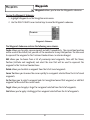
How GPS and Trackplotting Work
Your Humminbird® uses GPS and sonar to determine your position, display it on a grid, and
provide detailed underwater information. The Global Positioning System (GPS) is a satellite
navigation system designed and maintained by the U.S. Department of Defense. GPS was
originally intended for military use; however, civilians may also take advantage of its highly
accurate position capabilities, typically within +/- 10 meters, depending on conditions. This
means that 95% of the time, the GPS receiver will read a location within 10 meters of your
actual position. Your GPS Receiver also uses information from WAAS (the Wide Area
Augmentation System), EGNOS (the European Geostationary Navigation Overlay Service), and
MSAS (the MTSAT Satellite Augmentation System) satellites if they are available in your area.
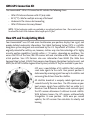
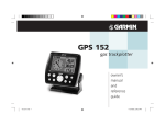
GPS uses a constellation of 24 satellites that continually
send radio signals to the earth. Your present position is
determined by receiving signals from up to 16 satellites and
measuring the distance from the satellites.
All satellites broadcast a uniquely coded signal once per
second at exactly the same time. The GPS receiver on your
boat receives signals from satellites that are visible to it.
Based on time differences between each received signal,
the GPS receiver determines its distance to each satellite.
With distances known, the GPS receiver mathematically
triangulates its own position. With once per second
updates, the GPS receiver then calculates its velocity and
bearing.
1
The GPS Receiver allows you to combine easy-to-use trackplotting and navigation capabilities
with advanced fishfinding. The following GPS functionality is currently supported by your
Fishing System when it is connected to the included GPS receiver:
•
•
•
•
•
View current position
View current track (breadcrumb trail)
View precision speed and heading from your GPS receiver
Save tracks and waypoints
Travel a route and navigate from one waypoint to the next.
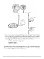
Connecting a GR16 GPS Receiver to the Fishfinder
Here's how to access GPS functionality using your GR16 GPS Receiver Accessory:
1. Attach the GR16 GPS receiver to your Fishfinder Control Head COM port using the
NMEA cable attached to the antenna.
2. If you are already using other Fishfinder accessories plugged into the COM connector,
you will also need to use the AS-YC ("Y") cable included in your GR16 GPS Hardware Kit
so that you can use both the accessories and your GPS Receiver at the same time.
Attach the COM connector of the "Y" cable directly to your Fishfinder Control Head
COM port. Attach the GR16 GPS receiver to the NMEA-COM connector of the "Y" cable.
Re-connect your Fishfinder accessories to the ACCY-COM connector of the "Y" cable.
3. Power up the Fishfinder Fishing System (see your Fishfinder Operation Manual for
details).
4. When the Fishfinder detects the NMEA input from the GPS Receiver, the Combo, Track
and Bird's Eye Views will be added automatically to the VIEW key function. A
Navigation menu tab and the Navigation X-Press™ menu will also be added
automatically to the Menu system.
2
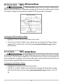
NMEA Output
5. The Fishfinder Control Head outputs NMEA signals thru the "pigtail" cable attached to
the end of the GR16 GPS Receiver Cable for connection to devices such as autopilots.
Connect the NMEA Out (White Wire) of the cable to the NMEA In of the device you are
connecting to your Fishfinder. The pinouts of this cable are as follows:
• Red Wire, +12V (output voltage only)
• Black Wire, Ground
• White Wire, NMEA Out.
CAUTION! Please use caution before connecting the red +12V wire to any other NMEA device.
This is an output voltage provided by the Fishfinder unit and GR16 receiver and should only be
connected to those NMEA devices that need a 12 volt input.
3
GPS Receiver Installation
To optimize performance of the GPS receiver, mount it in an area that has full exposure to the
sky. The effective area of reception is 10° above the horizon.
Different circumstances determine the mounting method appropriate for your GPS receiver.
If you have…
Then use:
An antenna stem with standard 1” – 14 thread
Stem Mount with 1" - 14 Thread
Access under mounting location
Access Under Mounting Location
No access under mounting location
No Access Under Mounting Location
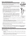
Stem Mount with 1” - 14 Thread
Receiver Head
Follow these steps to stem mount the GPS receiver:
1. If you have a pre-existing stem mount, skip to step 2. If you
need to mount the antenna pole (stem), determine the best
location, preplan and test the cable routing to your Fishfinder
unit before any drilling or cutting of your boat surfaces, then
route the 20’ (6 m) cable to the desired mounting location.
Mark the location and drill a 3/4” (19 mm) hole for the cable
and cable connector. If you have purchased hardware to stem
mount your GPS receiver, follow the instructions included with
that hardware to attach the stem to the boat.
Receiver
Base
Antenna
Stem
NOTE: 10’ extension cables may be purchased from Humminbird® if Stem Mount, Attaching
your planned cable route exceeds 20’ (6 m). Maximum cable length, Receiver Base to Stem
including extension cables, should not exceed 50’ (16 m). Visit our
website at www.humminbird.com, or call our Customer Resource
Center at 1-800-633-1468 to purchase extension cables.
2. Screw on the receiver base to the stem first, making sure
that the stem pipe does not protude from the receiver base.
This adds protection to the cable when pulling it through
the pipe stem. In addition to this, deburr the pipe edges to
reduce cable abrasion.
3. Use electrical tape to secure the NMEA pigtail to the cable as
shown in the illustration.
NMEA
Pigtail
Taped
NMEA
Pigtail
Cable Out
NMEA Pigtail
Taped to Cable
4
NOTE: Leave the NMEA pigtail secured to the cable unless needed in
order to make it easier to remove the GPS Receiver.
#6 - 1/4” Mounting
Screws
4. Route GPS Receiver cable through the stem and continue with
the planned cable route.
5. Attach the GPS Receiver to its base using the included #6 - 1/4”
screws. Hand tighten only.
Cable
Route
Access Under Mounting Location
Follow these steps to deck mount the GPS receiver when you can
route the cable down through the mounting surface:
Stem
Stop
Attaching the Receiver to
the Base, Making Sure
Cable is Not Pinched
1. Determine the best location, then test route the 20’ (6 m) cable
from the Fishfinder control head to the planned mounting
location of the GPS Receiver.
NOTE: 10’ extension cables may be purchased from Humminbird® if
your planned cable route exceeds 20’ (6 m). Maximum cable length,
including extension cables, should not exceed 50’ (16 m). Visit our
website at www.humminbird.com, or call our Customer Resource
Center at 1-800-633-1468 to purchase extension cables.
Access Under
Mounting Location
2. Mark the mounting location and drill a 3/4” (19 mm) hole for the cable and cable
connector. Secure the NMEA pigtail to the cable with electrical tape. Route the cable.
3. Cover the cable hole with the GPS Receiver. Make sure the Receiver is flush against the
surface and mark the two mounting holes with a pencil or awl.
4. Move the Receiver to the side and drill two pilot holes, using a 5/32” (4 mm) bit.
NOTE: Apply marine-grade silicone caulk or sealant to both screw and drilled holes as needed to
protect your boat from water damage.
5. Align the GPS Receiver’s screw holes over the pilot screw holes and attach with the
#6 - 3/4” Phillips head screws. Hand tighten only.
NOTE: If the mounting surface is thin or made of a light-weight material, you may need to add
reinforcing material below the mounting surface in order to support the GPS Receiver.
5
No Access Under Mounting Location
Follow these steps to deck mount the GPS Receiver in a situation
where you must route the cable to the side because there is no space
for a cable underneath the mounting location.
1. Determine the best location, then test route the 20’ (6 m) cable
from the Fishfinder control head to the planned mounting
location of the GPS Receiver.
No Access Under
Mounting Location
NOTE: 10’ extension cables may be purchased from Humminbird® if
your planned cable route exceeds 20’ (6 m). Maximum cable length,
including extension cables, should not exceed 50’ (16 m). Visit our
website at www.humminbird.com, or call our Customer Resource
Center at 1-800-633-1468 to purchase extension cables.
2. Confirm that the cable length is adequate and route the
cable from the Receiver to the Fishfinder control head. If
holes are required to route the cable, they must be 3/4” (19
mm) to allow for the cable connector. Secure the NMEA
pigtail with electrical tape.
NMEA
Pigtail
Taped
NMEA
Pigtail
Cable Out
NMEA Pigtail Taped
to Cable
3. The GPS Receiver has two wire routing notches. Use the cable notch closest to the
intended cable route.
4. With the cable routed, position the GPS Receiver in the planned mounting location
and mark the mounting holes with a pencil or awl.
5. Move the GPS Receiver to the side and drill the two 5/32” (4 mm) pilot holes.
NOTE: Apply marine-grade sillicone caulk or sealant to both screw and drilled holes as needed to
protect your boat from water damage.
6. Align the screw holes of the GPS Receiver over the pilot screw holes, referring to the
illustration, and attach with the #6 - 3/4 Phillips head screws. Hand tighten only.
Finish Routing the Cable and Check Operation
Follow these steps to finish routing the GPS Receiver cable between the Fishfinder control
head and the Receiver:
1. Secure the cable along its path to the Fishfinder control head as needed, using
cable ties.
2. Plug the GPS Receiver cable to the Fishfinder control head per the instructions detailed
in Connecting a GR16 GPS Receiver to the Fishfinder.
6
Views
Sonar
Views
The following views will be added to the View Rotation when a
GPS Receiver is connected to the Fishfinder Fishing System:
Combo
View
Bird's
Eye
View
Track
View
Navigation views:
• Bird’s Eye View
• Track View
• Combo View
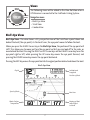
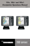
Bird’s Eye View
Bird's Eye View - This view shows a 3-D, perspective view of the track from a point above and
behind the boat (the eye point). As the boat turns, the eye point moves to follow the boat.
When you press the 4-WAY Cursor key in the Bird’s Eye View, the position of the eye point will
shift. This allows you to move and turn the eye point so that you can look off to the sides, or
even behind the boat. Pressing the RIGHT or LEFT arrow keys on the 4-WAY Cursor key turns the
eye point right or left, while pressing the UP arrow key moves the eye point forward, and
pressing the DOWN arrow key moves the eye point backward.
Pressing the EXIT key moves the eye point back to its original position behind and above the boat.
Bird’s Eye View
Depth
Latitude and
Longitude
Position of Boat
Speed of Boat
Boat Icon
Bearing of Boat
with Respect
to North
Water Surface
Temperature
7
Track View
Track View - This view shows the current track (also known as the position history or
breadcrumb trail) showing where the boat has been, along with saved tracks, waypoints, and
the current route (when navigating).
Track View with Active Cursor
Depth
Track Scale
Latitude and
Longitude
Position of
Cursor
Active Cursor
Distance to
Go To Cursor
Bearing of Boat
with Respect
to North
Bearing to
Cursor
Panning: Use the 4-WAY Cursor keys to move the grid around on the display in the direction of
the key being pressed. When you do this, a bullseye cursor is drawn at the center of the screen
and is linked to the boat by a gray line, even if the boat is off the screen.
8
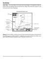
Combo View
Combo View - This view is displayed as a split screen, with Track View on the left and Sonar
View on the right side of the screen. The width of the sonar window can be changed.
Combo View
Depth
Sonar
Window
Track Scale
Water Surface
Temperature
Speed of Boat
Bearing of
Boat with
Respect
to North
View Orientation
Both Track and Combo views allow you to choose the orientation of the view. When North-Up
orientation is selected, North is shown at the top of the display. In other words, objects located
to the north of the boat are drawn above the boat. When Course-Up orientation is selected, the
direction of motion of the boat is shown at the top of the display. In other words, objects ahead
of the boat are drawn above the boat. In both orientations, the view pans automatically, so that
the boat is always centered on the display. When the boat is stationary, it is drawn as a circle.
When the boat is in motion, it takes on a boat shape, pointed in the direction of motion (always
Up in the Course-Up orientation).
9
Introduction to Navigation
Use your Fishfinder to establish waypoints at areas of interest and to navigate to those
waypoints via a route (representing the shortest intended distance between waypoints). You
can also view and save tracks, which represent the actual path of the boat.
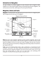
Waypoints, Routes and Tracks
Waypoints are stored positions that allow you to mark areas of interest or navigation points.
Your Fishing System can store up to 750 waypoints.
Waypoints, Routes and Tracks
Depth
Waypoint
Route
XTE: Cross
Track Error.
Distance of
Boat from
Route
Track
DTG: Distance
to Go to
Waypoint
BRG: Bearing
to Waypoint
Water Surface
Temperature
Speed of Boat
Bearing of
Boat with
Respect
to North
Routes link two or more waypoints together to create a path for navigation, and are used
in trip planning. A route represents your intended navigation and shows the shortest path
from each waypoint to the next. As you travel a route, staying on the route line is the most
efficient way to get to your destination, although you should always look out for obstacles
not shown on the chart.
Tracks consist of detailed position history, and are displayed as a breadcrumb trail of
trackpoints. The Current Track shows the position history since the unit was powered up
(maximum of 2000 trackpoints displayed). You can clear the Current Track or save it at any
time. Your Fishing System can store up to 10 saved tracks, each containing 2000
trackpoints. The current track represents your actual path so far.
10
Save, Edit, or Delete a Waypoint
Save your current position as a waypoint: On any view, press the MENU key to display the
X-Press™ menu. Select Mark and press the RIGHT Cursor key to save the current position of the
boat as a waypoint.
Save the cursor position as a waypoint: On the Track or Combo view, use the Cursor key to
designate the position you want to save as a waypoint. Then press the MENU key to display the
X-Press™ menu. Select Mark and press the RIGHT Cursor key to save the current position of the
boat as a waypoint.
Save a position from the sonar history: On the Sonar view, use the Cursor key to point to a
feature in the sonar history (also called the Sonar Saver feature). Then press the MENU key to
display the X-Press™ menu. Select Mark and press the RIGHT Cursor key to save the current
position of the boat as a waypoint. The new waypoint will also record the depth at that location.
NOTE: When you save a waypoint by any of these methods, a numerical waypoint name is
automatically assigned. You can edit the waypoint information later to give it a different name
and select an icon to represent it (see Waypoint submenu on the Navigation Main Menu Tab).
Display the Waypoints Submenu: From any view, press the MENU key twice to display the
Main Menu System, then use the RIGHT Cursor key to select the Navigation tab. Select
Waypoints and press the RIGHT Cursor key to display the Waypoints submenu.
Program a specific position as a waypoint: To create a waypoint that is NOT your current
position, from the Waypoints submenu, select the Create option and press the RIGHT Cursor
key. Use the Cursor keys to program a waypoint name, latitude, longitude, and icon before
selecting Save.
Edit a waypoint: From the Waypoints submenu, select Edit and press the RIGHT Cursor key
to display a list of saved waypoints. Select the waypoint you want to edit and press the
RIGHT Cursor key. Use the 4-WAY Cursor Control key to move from field to field, and the UP
and DOWN Cursor keys to changes values once you are in a field. In the Waypoint Name,
Latitude and Longitude fields, use the UP and DOWN Cursor keys to change the letter or
number. All upper and lower case letters are available, as well as digits 0-9 and some
punctuation characters. In the Waypoint Icon field, use the UP and DOWN Cursor keys to
change the icon used to represent the waypoint on the Combo and Track Views. You can
exit these fields with the LEFT and RIGHT Cursor keys or by pressing the EXIT key. Select
Save and press the RIGHT Cursor key to save your changes.
11
To make it easier to select a waypoint, select Sort By and press the RIGHT or LEFT Cursor keys to
select a sort order:
• Name shows the waypoints alphabetically
• Time shows the most recently-created waypoint first
• Distance shows the closest waypoint first.
Delete a waypoint: From the Waypoints submenu, select Delete and press the RIGHT Cursor
key to display a list of waypoints. Select the waypoint you want to delete, then press the RIGHT
Cursor key. You will be asked to confirm deletion before the waypoint is actually deleted.
Navigate to a Waypoint or Position
Navigate to the cursor position: From the Track or Combo view, use the Cursor key to select a
position or waypoint to which you want to navigate. Press the MENU key once to display the
Navigation X-Press™ menu. Select Go To and press the RIGHT Cursor key. Navigation will begin
immediately.
Navigate to a specified waypoint: Press the MENU key once to display the Navigation
X-Press™ menu. Select Go To and press the RIGHT Cursor key. Then choose the waypoint to
which you would like to navigate from the waypoint list and press the RIGHT Cursor key to
select it.
NOTE: By repeating the previous instructions, you can add more waypoints to create a longer
multi-segment route.
Skipping a waypoint: From the Navigation X-Press™ menu, select Skip Next Waypoint and
press the RIGHT Cursor key. If there is not another waypoint to skip to, navigation will be
cancelled.
Cancel navigation: From the Navigation X-Press™ menu, select Cancel Navigation and press the
RIGHT Cursor key. Canceling navigation removes the route and any waypoints created.
12
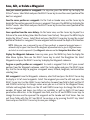
Add a Waypoint Target or Trolling Grid
Waypoint
Target
Track Scale
Add or Remove a Waypoint Target: From the Waypoints
submenu, select Target and press the RIGHT Cursor key
to display a list of waypoints. Select the waypoint you
want to target. A target consisting of concentric circles
centered on the selected waypoint will appear on all of
the navigation views; the target shows various distance
ranges from the targeted waypoint. To remove the
target, choose Remove Target from the Navigation
X-Press™ menu.
Track View with Target
Track Scale
Waypoint
Trolling Grid
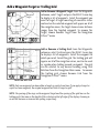
Add or Remove a Trolling Grid: From the Waypoints
submenu, select Grid and press the RIGHT Cursor key
to display a list of waypoints. Select the waypoint to
which you want to add the grid. The trolling grid will
appear on all of the navigation views, and can be used
as a guide when trolling around a waypoint. The grid
can be rotated to any desired heading using Grid
Rotation from the Navigation Main menu. To remove
the trolling grid, choose Remove Grid from the
Navigation X-Press™ menu.
Track View with Grid
NOTE: Only one waypoint can have either a target or a grid at one time. If you apply a target or
a grid to a new waypoint, the original waypoint will lose its target or grid.
NOTE: The spacing of the rings on the waypoint target and the spacing of the grid lines on the
trolling grid is the same as the length of the scale bar on the left edge of the display. Zooming in
or out will decrease or increase the spacing, respectively.
13
Save or Clear a Current Track
Save the current track: From the Navigation X-Press™ menu, select Save Current Track and
press the RIGHT Cursor key. The track will remain on the display, but will change from black to
gray. To remove the track completely from the display, see Edit, Delete or Hide Saved Tracks.
NOTE: When you save a track, a name is automatically assigned. The track name consists of a
date/time stamp, but can be re-named later (see Edit a Saved Track).
Clear the current track: From the Navigation X-Press™ menu, select Clear Current Track and
press the RIGHT Cursor key. The track will be removed from the display and discarded.
Edit, Delete or Hide Saved Tracks
Display the Tracks Submenu: From any view, press the MENU key twice to display the Main
Menu System, then use the RIGHT Cursor key to select the Navigation tab. Select Tracks and
press the RIGHT Cursor key to display the Tracks submenu.
Edit a saved track: From the Tracks submenu, select Edit and press the RIGHT Cursor key to
display the list of saved tracks. Select the track you want to edit and press the RIGHT Cursor key.
When the Edit Track dialog box appears, use the Cursor keys to move between fields. In the
Track Name field, the UP and DOWN Cursor keys change the letter or number. All upper and
lower case letters are available, as well as digits 0-9 and some punctuation characters. You can
exit the Track Name field with the LEFT and RIGHT Cursor keys or by pressing the EXIT key. Select
Save and press the RIGHT Cursor key to save your changes.
Delete a saved track: From the Tracks submenu, select Delete and press the RIGHT Cursor key
to display the list of saved tracks. Select the track you want to delete and press the RIGHT Cursor
key. You will be asked to confirm deletion before the track is actually deleted.
Hide or display a saved track: From the Tracks submenu, select Visibility and press the RIGHT
Cursor key to display the list of saved tracks. Select the track you want to hide or display and use
the Cursor keys to select Hidden or Visible. Press the EXIT key to return to the Tracks submenu.
14
The Menu System
The menu system is divided into easy-to-use menu modules. The main components of the
menu system are:
Start-Up Options Menu - Press the MENU key during the power up sequence to view the StartUp Options menu.
X-PressTM Menu
X-Press™ Menu - The X-Press™ menu allows you to access the
settings that are changed frequently without having to navigate
through the whole menu system. Press the MENU key once to display
t
h
e
X-Press™ Menu. When you select a menu item from the X-Press™
menu, the menu will collapse, leaving only the menu choice on the
screen. Use the UP or DOWN Cursor keys to reactivate the X-Press™
menu.
NOTE: The X-Press™ Menu choices will vary depending on which view is
active when you press the MENU key, as well as whether you are in
Normal or Advanced User Mode. Either the Sonar or Navigation
X-Press™ Menu will appear, depending on the view you are in.
Main Menu Tabs - Less frequently-adjusted menus are grouped into the Main Menu System.
The Main Menu system is organized under the following tab headings to help you find a
specific menu item quickly: Alarms, Sonar, Navigation (if the GPS Receiver is attached), Setup,
and Accessories.
Press the MENU key twice for the Main Menu, then use the 4-WAY
Cursor LEFT or RIGHT key to select a tab, and use the DOWN or UP key
to select a specific menu item under that tab, then use the LEFT or
RIGHT keys again to change a menu setting. Press the EXIT key to
move quickly to the top of the tab. A down arrow at the bottom of a
menu means that you can scroll to additional menu choices using
the DOWN Cursor key. A right or left arrow on a menu choice means
that you can use the RIGHT or LEFT Cursor keys to make changes or
to see more information.
Main Menu System
Normal User Mode
NOTE: The Main Menu choices will vary depending on whether you are
in Normal or Advanced User Mode.
15
User Mode (Normal or Advanced) - An Advanced Mode is provided for users who desire the
highest level of control over the Fishing System and Normal Mode for users who desire greater
simplicity and fewer menu choices. Additional Advanced menu choices will be displayed
throughout the menu system when you navigate to specific menus while in Advanced Mode.
Any changes made while in Advanced Mode will remain in effect after you switch back to
Normal Mode. For example, if you set specific views to be visible while in Advanced User Mode,
and then return to Normal User Mode, those views will still be visible. See Setup Menu Tab: User
Mode for specific instructions on changing to Advanced User Mode.
Sonar Tab, Normal Mode
Sonar Tab, Advanced Mode
Total Screen Update - when you change any menu settings that affect the Sonar View, the view
will update immediately (i.e. you don’t have to exit the menu to apply the change to the
screen). For instance, by switching between "Inverse" and "Structure ID®" from the X-Press™
menu it is possible to alternate quickly between the two viewing methods.
16
Start-Up Options Menu
Press the MENU key when the Title screen is displayed to
access the Start-Up Options menu.
Use the UP or DOWN 4-WAY Cursor keys to position the
cursor, then the RIGHT Cursor key to select one of the
following choices. If you wait too long, the system will
default to whichever menu mode happens to be
highlighted:
• Normal
• Simulator
• System Status
• PC Connect (use with PC Connect Cable).
Start-Up Options Menu
See the following paragraphs for more information about each of these choices.
Normal Operation
Use Normal operation for on the water operation with a transducer connected. In addition,
your Fishing System uses advanced transducer detection methods to determine if a transducer
is connected. If a functioning transducer is connected, Normal operation will be selected
automatically at power up and your Fishing System can be used on the water.
Exit Normal operation by powering your Fishing System off.
Simulator
Use the Simulator to learn how to use your Fishing
System before taking your boat on the water. The
Simulator is a very powerful tool that simulates on the
water operation, providing a randomly-updated display.
We recommend going through this manual while using
the Simulator, since all of the menus function and affect
the display the way they actually do when in Normal
operation.
Simulator, Shown with Optional
WeatherSenseTM Accessory
17
NOTE: To get the full benefit of the Simulator, it is important to select Simulator manually
from the Start-Up Options menu as opposed to letting the Fishing System enter Simulator
automatically (as it will if a transducer is not connected and you do nothing during power
up). Manually selecting Simulator from the Start-Up Options menu allows you to preconfigure your Fishing System for on the water operation. Any menu changes you make will
be saved for later use.
A message will appear on the display periodically to remind you that you are using the
Simulator.
Exit the Simulator by powering your Fishing System off.
System Status
Use System Status to view system connections and to conduct a unit self-test.
The following screens are displayed in turn when you press the VIEW button when using
System Status:
• Self Test
• Accessory Test
• GPS Diagnostic View.
Exit System Status by powering your Fishing System off.
Self Test
Self Test displays results from the internal diagnostic self
test, including unit serial number, Printed Circuit Board
(PCB) serial number, software revision, total hours of
operation and the input voltage.
System Status Self Test Screen
18
Accessory Test
Accessory Test lists the accessories connected to the
system.
NOTE: The speed accessory will be detected only if the
paddlewheel has moved since your Fishing System was
powered up.
NOTE: GPS will be shown as Connected when your
Fishing System detects your GR16 GPS Receiver.
Accessory Test Screen
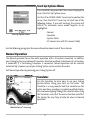
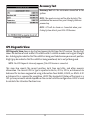
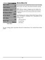
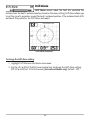
GPS Diagnostic View
GPS Diagnostic View shows a sky chart and numerical data from the GPS receiver. The sky chart
shows the location of each visible GPS satellite with its satellite number and a signal strength
bar. A dark gray bar indicates that the satellite is being used to determine your current position.
A light gray bar indicates that the satellite is being monitored, but is not yet being used.
NOTE: The GPS Diagnostic View only appears if the GPS Receiver is connected.
This view also reports the current position, local time and date, and other numeric
information. The current GPS Fix Type is reported as No Fix, 2D Fix, 3D Fix, or Enhanced. An
Enhanced fix has been augmented using information from WAAS, EGNOS, or MSAS. A 3D
or Enhanced Fix is required for navigation. HDOP (the Horizontal Dilution of Precision) is a
GPS system parameter which depends on the current satellite configuration. HDOP is used
to calculate the Estimated Position Error.
19
PC Connect
(With PC Connect Cable only)
Use PC Connect to update the software of the Fishing System control head. This feature
requires the use of the PC Connect Cable. Complete instructions are included with the PC
Connect Cable accessory.
NOTE: The PC Connect Cable requires a separate purchase. For more information visit our
website at www.humminbird.com or contact our Customer Resource Center at 1-800-633-1468.
Exit PC Connect mode by powering the Fishing System off.
20
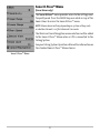
Sonar X-Press™ Menu
(Sonar Views only)
The Sonar X-Press™ menu provides access to the settings most
frequently-used. Press the MENU key once while in any of the
Sonar Views to access the Sonar X-Press™ menu.
NOTE: Menu choices will vary depending on system settings such
as whether the unit is set for Advanced User mode.
The Mark and Cancel Navigation menu selections will be added
to the Sonar X-Press™ Menu when a GPS is connected to the
Fishing System.
See your Fishing System Operations Manual for information on
the standard Sonar X-Press™ Menu choices.
Sonar X-PressTM Menu
21
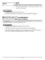
Mark
Mark allows you to mark the position of a waypoint, either at
the current boat location, or, if the Cursor is active, at the
current Cursor location.
To Mark a Waypoint:
1. Highlight Mark on the Sonar X-Press™ menu.
2. Use the RIGHT 4-Way Cursor Control key to mark the location of a Waypoint.
Cancel Navigation
(only when Navigating)
Cancel Navigation discards the current route and exits Navigation Mode. This menu choice will
only appear when you are currently navigating a route.
To Cancel Navigation:
1. Highlight Cancel Navigation on the Sonar X-Press™ menu.
2. Use the RIGHT 4-WAY Cursor Control key to initiate canceling navigation.
3. The Confirm dialog box will appear. To cancel navigation, press the RIGHT Cursor key
once more. To avoid canceling navigation, press the LEFT Cursor key.
22
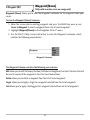
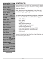
Navigation X-Press™ Menu
(Navigation Views only)
The Navigation X-Press™ menu provides access to the settings
most frequently used. Press the MENU key once while in the
Bird's Eye View, the Track or the Combo View to access the
Navigation X-Press™ menu.
NOTE: Menu choices will vary depending on system settings,
such as whether you are currently navigating.
The Navigation X-Press™ menu will be added to the menu
system when a GPS is connected to the Fishing System, and will
contain the following choices:
Navigation X-PressTM Menu
• Mark
• Zoom
• Go To
• Waypoint [Name]
• Cursor to Waypoint
• Save Current Track
• Clear Current Track
• Skip Next Waypoint (Only When Navigating)
• Cancel Navigation (Only When Navigating)
• Remove Target (Only if a Target is Active)
• Remove Grid (Only if a Grid is Active)
• Sonar Window (Combo View Only)
• Waypoint [Name].
23
Mark
Mark allows you to mark the position of a waypoint, either
at the current boat location, or, if the Cursor is active, at the current Cursor location.
To Mark a Waypoint:
1. Highlight Mark on the Navigation X-Press™ menu.
2. Use the RIGHT 4-Way Cursor Control key to mark the location of a Waypoint.
Zoom
Zoom allows you to change the scale of the Bird's Eye, Track
and Combo Views.
To Zoom:
1. Highlight Zoom on the Navigation X-Press™ menu.
2. Use the LEFT or RIGHT 4-WAY Cursor Control keys to increase or decrease the Zoom
level.
Go To
Go To allows you to start Navigation towards a waypoint.
If the Cursor is active, choosing Go To creates a waypoint and starts navigation towards that
waypoint; if the Cursor is not active, choosing Go To displays the list of waypoints, so that you
can select the waypoint towards which you want to navigate.
To Begin Navigation:
1. Highlight Go To on the Navigation X-Press™ menu.
2. Use the RIGHT 4-WAY Cursor Control key to begin navigation. Navigation will begin
immediately if the Cursor is active or the Waypoint selection list will appear. Select a
waypoint and navigation will begin immediately.
24
Waypoint [Name]
(Only with an active cursor on a waypoint)
Waypoint [Name] allows you to view the Waypoints submenu for the waypoint under your
cursor.
To view the Waypoint [Name] Submenu:
1. Move the cursor onto an existing waypoint and press the MENU key once, or use
Cursor to Waypoint to select a waypoint from a list of saved waypoints.
2. Highlight Waypoint[Name] on the Navigation X-Press™ menu.
3. Use the RIGHT 4-Way Cursor Control key to view the Waypoints submenu, which
contains the following menu choices:
Waypoint Submenu
The Waypoint Submenu contains the following menu choices:
Edit allows you to edit the Name, Position (Latitude and Longitude) and select the Icon that will
be used to represent the waypoint in the Chart and Combo Views.
Delete allows you to delete a waypoint from the list of saved waypoints.
Target allows you to apply a target to a waypoint selected from the list of waypoints.
Grid allows you to apply a trolling grid to a waypoint selected from the list of waypoints.
25
Cursor to Waypoint
(Chart or Combo view only)
Cursor to Waypoint allows you to quickly move the cursor to any saved waypoint, so that you
can locate it or edit it.
NOTE: This X-Press™ menu item appears only if you have saved waypoints.
To move cursor to a saved waypoint:
1. Highlight Cursor to Waypoint on the Navigation X-Press™ menu.
2. Use the RIGHT 4-WAY Cursor Control key to initiate Cursor to Waypoint.
3. Use the UP or DOWN 4-WAY Cursor Control key to highlight the waypoint you wish to
move the cursor to, then use the RIGHT 4-WAY Cusor Control key to select the
destination waypoint.
Save Current Track
Save Current Track allows you to save the current track
being displayed. After the current track is saved, a new current track is started.
To Save Current Track:
1. Highlight Save Current Track on the Navigation X-Press™ menu.
2. Use the RIGHT 4-WAY Cursor Control key to initiate saving the current track.
3. The Confirm dialog box will appear. To save the current track, press the RIGHT Cursor
key once more. To cancel saving the current track, press the LEFT Cursor key.
Clear Current Track
Clear Current Track allows you to clear the current track
being displayed and start a new track at the present position.
To Clear Current Track:
1. Highlight Clear Current Track on the Navigation X-Press™ menu.
2. Use the RIGHT 4-WAY Cursor Control key to initiate clearing the current track.
3. The Confirm dialog box will appear. To clear the current track, press the RIGHT Cursor
key once more. To cancel clearing the current track, press the LEFT Cursor key.
26
Skip Next Waypoint
(Only When Navigating)
Skip Next Waypoint removes the next waypoint from the current route. This menu choice will
only appear when you are currently navigating a route.
To Skip Next Waypoint:
1. Highlight Skip Next Waypoint on the Navigation X-Press™ menu.
2. Use the RIGHT 4-WAY Cursor Control key to initiate skipping the next waypoint.
3. The Confirm dialog box will appear. To skip the next waypoint, press the RIGHT Cursor
key once more. To cancel skipping the next waypoint, press the LEFT Cursor key.
Cancel Navigation
(Only When Navigating)
Cancel Navigation discards the current route and exits Navigation Mode. This menu choice will
only appear when you are currently navigating a route.
To Cancel Navigation:
1. Highlight Cancel Navigation on the Navigation X-Press™ menu.
2. Use the RIGHT 4-WAY Cursor Control key to initiate canceling navigation.
3. The Confirm dialog box will appear. To cancel navigation, press the RIGHT Cursor key
once more. To avoid canceling navigation, press the LEFT Cursor key.
Remove Target
(Only if a Target is Active)
Remove Target removes the waypoint target from the display. This menu choice will only
appear when a target has already been applied to a waypoint.
To Remove a Target:
1. Highlight Remove Target on the Navigation X-Press™ menu.
2. Use the RIGHT 4-WAY Cursor Control key to remove the target.
27
Remove Grid
(Only if a Grid is Active)
Remove Grid removes the waypoint grid from the display. This menu choice will only appear
when a grid has already been applied to a waypoint.
To Remove a Grid:
1. Highlight Remove Grid on the Navigation X-Press™ menu.
2. Use the RIGHT 4-WAY Cursor Control key to remove the grid.
Sonar Window
(Combo View only)
Sonar Window sets the size of the Sonar Window in the Combo View. Sonar Window can only
be accessed from the Combo View.
To Set the Size of the Sonar Window in the Combo View:
1. Highlight Sonar Window on the Navigation X-Press™ menu.
2. Use the LEFT or RIGHT 4-WAY Cursor Control keys to adjust the size of the sonar
window. (Wide, Medium, Narrow, Default = Medium)
Waypoint [Name]
(Most recently-created waypoint)
Waypoint [Name] allows you to view the waypoints submenu for the most recently created
waypoint.
NOTE: You must have selected MARK from the X-Press™ menu at least once since you last
powered up for this menu choice to appear.
To view the Waypoint [Name] Submenu:
1. Move the cursor to the desired position and select Mark from the X-Press™ menu to
save a waypoint.
2. Highlight Waypoint[Name] on the Navigation X-Press™ menu.
3. Use the RIGHT 4-Way Cursor Control key to view the Waypoints submenu.
28
Waypoint [Name] Submenu
The Waypoint Submenu contains the following menu choices:
Edit allows you to edit the Name, Position (Latitude and Longitude) and select the Icon that will
be used to represent the waypoint in the Chart and Combo Views.
Delete allows you to delete a waypoint from the list of saved waypoints.
Go To allows you to select a waypoint and start navigation toward that waypoint, or add that
waypoint to the end of the current route.
Target allows you to apply a target to a waypoint selected from the list of waypoints.
Grid allows you to apply a trolling grid to a waypoint selected from the list of waypoints.
29
Navigation Menu Tab
Press the MENU key twice to access the Main Menu System,
then press the RIGHT cursor key to select the Navigation tab.
NOTE: Menu choices will vary depending on system settings.
The Navigation Menu Tab will be added to the menu system
when the GR16 is connected to your Fishing System, and the
following menu choices will appear in the menu tab:
Navigation Menu Tab
• Current Track
• Saved Tracks
• Waypoints
• View Orientation
• North Reference
• Grid Rotation
• Trackpoint Interval
• Track Min Distance (Advanced)
• Map Datum (Advanced)
• Course Projection Line
• Delete All Nav Data (Advanced).
30
Current Track
Current Track allows you to view the Current Track submenu.
To view the Current Track Submenu:
1. Highlight Current Track on the Navigation main menu.
2. Use the RIGHT 4-WAY Cursor Control keys to view the Current Track submenu.
Current Track Submenu
The Current Track Submenu contains the following menu choices:
Save Current Track allows you to save the current track.
Clear Current Track allows you to clear the current track.
Appearance allows you to change the style and color of the current track. (Breadcrumb Trail,
Dashed Line, or Solid Line, and if a line, the color of the line, from light to dark gray to black).
Saved Tracks
Saved Tracks allows you to view the Saved Tracks submenu.
To view the Saved Tracks Submenu:
1. Highlight Saved Tracks on the Navigation main menu.
2. Use the RIGHT 4-WAY Cursor Control keys to view the Saved Tracks submenu.
Saved Tracks Submenu
The Saved Tracks Submenu contains the following menu choices:
Edit allows you to select a previously-saved track and edit its name, whether it is visible or not,
and its appearance.
Delete allows you to delete a track from a list of previously-saved tracks.
Default sets the appearance of the track created by selecting Save Current Track.
31
Waypoints
Waypoints allows you to view the Waypoints submenu.
To view the Waypoints Submenu:
1. Highlight Waypoints on the Navigation main menu.
2. Use the RIGHT 4-WAY Cursor Control keys to view the Waypoints submenu.
Waypoints Submenu
The Waypoints Submenu contains the following menu choices:
Create allows you to create a new waypoint and edit it immediately. The current boat position
will be used as the default, but you can set the coordinates to any valid position. The Icon used
to represent the waypoint in the Track and Combo Views can also be changed.
Edit allows you to choose from a list of previously-saved waypoints, then edit the Name,
Position (Latitude and Longitude) and select the Icon that will be used to represent the
waypoint in the Track and Combo Views.
Delete allows you to delete a waypoint from the list of saved waypoints.
Cursor To allows you to move the cursor quickly to a waypoint selected from the list of saved
waypoints.
Go To allows you to select a waypoint and start navigation toward that waypoint, or add that
waypoint to the end of the current route.
Target allows you to apply a target to a waypoint selected from the list of waypoints.
Grid allows you to apply a trolling grid to a waypoint selected from the list of waypoints.
32
View Orientation
View Orientation allows you to select whether the Track
and Combo Views should be drawn North-Up or Course-Up.
To change the View Orientation setting:
1. Highlight View Orientation on the Navigation main menu.
2. Use the LEFT or RIGHT 4-WAY Cursor Control keys to change the View Orientation
setting. (North-Up, Course-Up, Default = North-Up)
NOTE: The View Orientation setting does not apply to the Bird's Eye View.
North Reference
North Reference allows you to have bearings displayed
with one of two orientations: True North or Magnetic North.
To change the North Reference setting:
1. Highlight North Reference on the Navigation main menu.
2. Use the LEFT or RIGHT 4-WAY Cursor Control keys to change the North Reference setting.
(True, Magnetic, Default = True)
Grid Rotation
Grid Rotation allows you to set the orientation of the
trolling grid in degrees, where a setting of 0° displays a standard North, South, East, West
alignment. See Waypoints for information on how to set a Grid.
To change the Grid Rotation setting:
1. Highlight Grid Rotation on the Navigation main menu.
2. Use the LEFT or RIGHT 4-WAY Cursor Control keys to change the Grid Rotation setting.
(0° to 89°, Default = 0°)
33
Trackpoint Interval
Trackpoint Interval allows you to select the time period
between trackpoints. The current track can only contain up to 2000 trackpoints, so longer time
periods cause the track to extend back further in time, but will be less detailed.
NOTE: Trackpoint Interval works in conjunction with Track Min Distance. Both conditions must
be met before a trackpoint is added to the current track.
To change the Trackpoint Interval setting:
1. Highlight Trackpoint Interval on the Navigation main menu.
2. Use the LEFT or RIGHT 4-WAY Cursor Control keys to change the Trackpoint Interval
setting. (1 second, 5 seconds, 10 seconds, 15 seconds, 30 seconds or 60 seconds,
Default = 15 seconds)
NOTE: During slow travel or drift, setting both Trackpoint Interval and Track Min Distance to
small values will allow you to increase the track resolution.
Track Min Distance
(Advanced)
Track Min Distance allows you to set a minimum distance of travel before a trackpoint is added
to the track. The Track Min Distance menu choice is only available when User Mode is set to
Advanced (see Setup Menu Tab: User Mode).
NOTE: Track Min Distance works in conjunction with Trackpoint Interval. Both conditions must
be met before a trackpoint is added to the current track.
NOTE: See Setup Menu Tab: User Mode in your Fishing System Operations manual.
To change the Track Minimum Distance setting:
1. Make sure you are in Advanced User Mode, then highlight Track Min Distance on the
Navigation main menu.
2. Use the LEFT or RIGHT 4-WAY Cursor Control keys to change the Track Min Distance
setting. (1 to 300 feet or 1 to 100 meters [International Units Only], Default = 16 ft, 5 m)
NOTE: During slow travel or drift, setting both Trackpoint Interval and Track Min Distance to
small values will allow you to increase the track resolution.
34
Map Datum
(Advanced)
Map Datum allows you to change the map coordinate system used by the Fishing System to
match those of a paper map. The Map Datum menu choice is only available when User Mode
is set to Advanced (see Setup Menu Tab: User Mode).
NOTE: See Setup Menu Tab: User Mode in your Fishing System Operations manual.
To change the Map Datum setting:
1. Make sure you are in Advanced User Mode, then highlight Map Datum on the
Navigation main menu.
2. Use the LEFT or RIGHT 4-WAY Cursor Control keys to change the Map Datum setting.
(Default = WGS 84)
Course Projection Line
Course Projection Line allows you to display or hide an
arrow extending from the bow of the boat that projects your current course, and shows where
the boat will go if you continue on your present course.
To change the Course Project Line setting:
1. Highlight Course Projection Line on the Navigation main menu.
2. Use the LEFT or RIGHT 4-WAY Cursor Control keys to change the Course Projection Line
setting (Hidden, Visible, Default = Hidden)
Delete All Nav Data
(Advanced)
Delete All Nav Data allows you to delete all saved Tracks and Waypoints. This menu choice
should be used with caution. The Delete All Nav Data menu choice is only available when User
Mode is set to Advanced (see Setup Menu Tab: User Mode).
NOTE: See Setup Menu Tab: User Mode in your Fishing System Operations manual.
To Delete All Navigation Data:
1. Make sure you are in Advanced User Mode, then highlight Delete All Nav Data on the
Navigation main menu.
2. Use the RIGHT 4-WAY Cursor Control key to delete all navigation data.
35
Alarms Menu Tab
From any view, press the MENU key twice to access the Main
Menu System. The Alarms tab will be the default selection.
NOTE: When an alarm is triggered, you can silence it by
pressing any key. The alarm will be silenced, and will not be
triggered again until a new instance of the alarm condition
is detected.
The following menu choices will be added to your Alarms
Menu Tab when a Handheld GPS is connected to the
Fishing System:
Alarms Menu
• Off Course Alarm
• Arrival Alarm
• Drift Alarm.
See your Fishing System Operations Manual for information on the standard Alarm Menu
choices.
36
Off Course Alarm
Off Course Alarm sounds when the boat has moved too far
off course based on the menu setting when navigating. Off Course Alarm allows you to set how
far the boat is allowed to move off course before the Off Course Alarm will sound.
Off Course Limits
Arrival Alarm Circle
To change the Off Course Alarm setting:
1. Highlight Off Course Alarm on the Alarms main menu.
2. Use the LEFT or RIGHT 4-WAY Cursor Control keys to change the Off Course Alarm
setting. (Off, 25 to 3000 feet, 10 to 1000 meters [International Models only], Default =
300 ft, 100 m)
Arrival Alarm
Arrival Alarm sounds when the boat has either exceeded
the distance to the destination waypoint, or has entered the Arrival Alarm Circle, based on the
menu setting when navigating. Arrival Alarm allows you to set how close the boat must be to
the destination waypoint before the Arrival Alarm will sound.
To change the Arrival Alarm setting:
1. Highlight Arrival Alarm on the Alarms main menu.
2. Use the LEFT or RIGHT 4-WAY Cursor Control keys to change the Arrival Alarm setting.
(Off, 25 to 3000 feet, 10 to 1000 meters [International Models only], Default = 150 ft, 50
m)
37
Drift Alarm
Drift Alarm sounds when the boat has exceeded the
distance from the boat’s anchored position, based on the menu setting. Drift Alarm allows you
to set the size of a perimeter around the boat’s anchored position; if the anchored boat drifts
outside of that perimeter, the Drift Alarm will sound.
Drift Alarm Circle
Drift Alarm Perimeter
To change the Drift Alarm setting:
1. Highlight Drift Alarm on the Alarms main menu.
2. Use the LEFT or RIGHT 4-WAY Cursor Control keys to change the Drift Alarm setting.
(Off, 25 to 3000 feet, 10 to 1000 meters [International Models only], Default = Off)
38
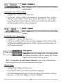
Setup Menu Tab
From any view, press the MENU key twice to access the tabbed
Main Menu System, then press the RIGHT cursor key until the
Setup tab is selected.
NOTE: Menu choices will vary depending on system settings such
as whether the unit is set for Advanced User mode and what
accessories are attached to the unit.
The following menu choices will be added to your Setup Menu
Tab when a Handheld GPS is connected to the Fishing System:
• Units - Distance
• Units - Speed
• Triplog Reset
• Local Time Zone (Advanced)
• Daylight Savings Time (Advanced)
• Position Format (Advanced)
• Time Format (Advanced, International Only)
• Date Format (Advanced, International Only)
• NMEA Format.
See your Fishing System Operations Manual for information on
the standard Setup Menu choices
Setup Menu Tab
39
Units - Distance
Units - Distance selects the units of measure for all distancerelated readouts.
To change the Units - Distance setting:
1. Highlight Units - Distance on the Setup menu.
2. Use the LEFT or RIGHT 4-WAY Cursor Control keys to change the Units - Distance
setting. (Domestic Models: Statute Miles, Nautical Miles; Default = Statute Miles;
International Models: Meters/Kilometers, Meters/Nautical Miles, Feet/Statute Miles,
Feet/Nautical Miles; Default = Meters/Kilometers)
Units - Speed
Units - Speed selects the units of measure for speed-related
readouts.
To change the Units - Speed setting:
1. Highlight Units - Speed on the Setup menu.
2. Use the LEFT or RIGHT 4-WAY Cursor Control keys to change the Units - Speed setting.
(kph [International Models only], mph, kts, Default = kph for International models and
mph for Domestic models)
Triplog Reset
Triplog Reset resets the Triplog to zero. The Triplog provides
the following information: timer for elapsed time, distance
traveled since last reset, and average speed.
NOTE: See Setup Menu Tab: Select Readouts (Advanced) in your Fishing System Operations
manual to find out how to display Triplog information on the screen.
To Reset Triplog:
1. Highlight Reset Triplog on the Setup menu.
2. Use the RIGHT 4-WAY Cursor Control key to initiate Triplog Reset.
3. The Confirm dialog box will appear. To reset the Triplog, press the RIGHT Cursor key
once more. To cancel Reset Triplog, press the LEFT Cursor key.
40
Local Time Zone
(Advanced)
Local Time Zone selects your time zone in reference to the time reported by the GPS receiver
when Time+Date is selected as a Digital Readout on the Sonar View (see Select Readouts). This
menu choice is available only when in Advanced User Mode (see Setup Menu Tab: User Mode.)
NOTE: See Setup Menu Tab: Select Readouts and User Mode in your Fishing System
Operations manual.
To change the Local Time Zone:
1. Make sure you are in Advanced User Mode, then highlight Local Time Zone on the
Setup menu.
2. Use the LEFT or RIGHT 4-WAY Cursor Control keys to change the Local Time Zone
(Default = EST [UTC-5] - Eastern Standard Time).
Daylight Saving Time
(Advanced)
Daylight Saving Time adjusts the time display to account for local Daylight Saving Time.
Selecting On adds one hour to the time display adjusted for your local time zone. Selecting Off
leaves the time display as adjusted for your local time zone. This menu choice is available only
when in Advanced User Mode (see Setup Menu Tab: User Mode.)
NOTE: See Setup Menu Tab: User Mode in your Fishing System Operations manual.
To change the Daylight Saving Time setting:
1. Make sure you are in Advanced User Mode, then highlight Daylight Saving Time on
the Setup menu.
2. Use the LEFT or RIGHT 4-WAY Cursor Control keys to turn Daylight Saving Time On or
Off. (Off, On, Default = Off)
41
Position Format
(Advanced)
Position Format selects the format of the latitude and longitude position display. This menu
choice is available only when in Advanced User Mode (see Setup Menu Tab: User Mode.)
NOTE: See Setup Menu Tab: User Mode in your Fishing System Operations manual.
To change the Position Format setting:
1. Make sure you are in Advanced User Mode, then highlight Position Format on the
Setup menu.
2. Use the LEFT or RIGHT 4-WAY Cursor Control keys to change the Position Format.
(dd.ddddd°, dd°mm.mmm', or dd°mm'ss", Default = dd°mm.mmm')
Time Format
(Advanced, International only)
Time Format changes the time format used by the unit. This menu choice is available only
when in Advanced User Mode (see Setup Menu Tab: User Mode.) International Models only.
Time Format selects a 12 hour or 24 hour format for the time of day displayed when Time + Date
is selected as a Digital Readout on the Sonar View (see Select Readouts).
NOTE: See Setup Menu Tab: Select Readouts and User Mode in your Fishing System Operations
manual.
To change the Time Format:
1. Make sure you are in Advanced User Mode, then highlight Time Format on the Setup
menu.
2. Use the LEFT or RIGHT 4-WAY Cursor Control keys to change the Time Format. (12 hour,
24 hour, Default = 12 hour)
42
Date Format
(Advanced, International only)
Date Format changes the date format used by the unit. This menu choice is available only when
in Advanced User Mode (see Setup Menu Tab: User Mode.) International Models only. Date
Format selects the format for the date display when Time + Date is selected as a Digital Readout
on the Sonar View. (see Select Readouts).
NOTE: See Setup Menu Tab: Select Readouts and User Mode in your Fishing System Operations
manual.
To change the Date Format:
1. Make sure you are in Advanced User Mode, then highlight Date Format on the
Setup menu.
2. Use the LEFT or RIGHT 4-WAY Cursor Control keys to change the Date Format.
(mm/dd/yy, dd.mm.yy or yy.mm.dd, Default = mm/dd/yy)
NMEA Output
(Advanced)
NMEA Output turns the NMEA output on or off. This menu choice is available only when in
Advanced User Mode (see Setup Menu Tab: User Mode.)
NOTE: See Setup Menu Tab: User Mode in your Fishing System Operations manual.
The following NMEA sentences are output:
DPT- Depth
MTW - Water Temperature
GLL - Lat/Lon Position
GGA - GPS Fix Data
RMC - Recommended Minimum Specific GNSS Data
VTG - Course Over Ground and Ground Speed
ZDA - Time and Date
When navigating, the following NMEA sentences are also output:
APB - Autopilot Sentence B
BWR - Bearing and Distance to Waypoint
RMB - Recommended Minimum Navigation Info
43
To turn NMEA Output on or off:
1. Make sure you are in Advanced User Mode, then highlight NMEA Output on the Setup
menu.
2. Use the LEFT or RIGHT 4-WAY Cursor Control keys to change the NMEA Output to On
or Off (Off, On, Default = Off)
44
Troubleshooting
Before contacting the Humminbird® Customer Resource Center, please read the following
section. Taking the time to review these troubleshooting guidelines may allow you to solve a
performance problem yourself, and therefore avoid sending your unit back for repair.
Fishing System Doesn’t Power Up
If your Fishing System doesn’t power up, use the Installation Guide that also comes with it for
specific confirmation details, making sure that:
• the power cable is properly connected to the Fishing System control head,
• the power cable is wired correctly, with red to positive battery terminal and black to
negative terminal or ground
• the fuse is operational
• the battery voltage of the power connector is at least 10 Volts.
Correct any known problems, including removing corrosion from the battery terminals or
wiring, or actually replacing the battery if necessary.
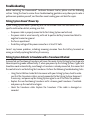
Fishing System Defaults to Simulator with a Transducer Attached
A connected and functioning transducer will cause the newly-started Fishing System to go into
Normal operating mode automatically. If, when you power up the Fishing System, it goes into
Simulator mode automatically, even though a transducer is already connected, this means that
the control head is not detecting the transducer. Perform the following troubleshooting tasks:
• Using the Installation Guide that also comes with your Fishing System, check to make
sure that the transducer cable is securely connected to the Fishing System. Reconnect
if necessary, and power up the Fishing System again to see if this fixes the problem.
• Replace the non-functioning transducer with a known good transducer if available
and power up the control head again.
• Check the transducer cable. Replace the transducer if the cable is damaged or
corroded.
45
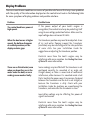
Display Problems
There are several main conditions or sources of possible interference that may cause problems
with the quality of the information displayed on the control head. Look in the following table
for some symptoms of display problems and possible solutions:
Problem
Possible Cause
The control head loses power at
high speeds.
If the power output of your boat’s engine is
unregulated, the control head may be protecting itself
using its over-voltage protection feature. Make sure the
input voltage does not exceed 20 Volts.
When the boat moves at higher
speeds, the bottom disappears
or suddenly weakens, or the
display contains gaps.
The transducer position may need to be adjusted. A mix
of air and water flowing around the transducer
(cavitation) may be interfering with the inter-pretation
of sonar data. See your Installation Guide for
suggestions on adjusting the transducer position.
Electrical noise from the boat’s engine may be
interfering with sonar reception. See Finding the Cause
of Noise for more information.
There are no fish detected, even
when you know they are in the
water under the boat, or sonar
readings seem weak or faulty.
Sonar readings may be affected if the transducer is not
positioned correctly (i.e. mounted at an angle, not
straight down), or there is some kind of mechanical
interference, either because it is mounted inside a hull
that is too thick for proper sonar transmission, the bond
between the transducer and the hull is not airtight, or
because the transducer is dirty. Check with your
Installation Guide for guidance on re-positioning the
transducer, and make sure the transducer is clean.
Low battery voltage may be affecting the power of
signal transmission.
Electrical noise from the boat’s engine may be
interfering with sonar reception. See Finding the Cause
of Noise for more information.
46
Finding the Cause of Noise
Electrical noise usually affects the display with many black dots at high speeds, and high
sensitivity readings. One or more of the following sources can cause noise or interference:
Possible Source of Noise
Isolation
Other electronic devices
Turn off any nearby electronic devices to see if the
problem goes away, then turn them on one at a time
to see if the noise re-appears.
The boat’s engine
To determine whether the boat’s engine is the source of
the noise, increase the RPMs while the boat is in neutral
and stationary to see if the noise increases proportionately; if noise appears when you rev the engine,
the problem could be the spark plugs, alternator, or
tachometer wiring. Replace the spark plugs with resistor
plugs, install an alternator filter, or route the control head
power and transducer cables away from the engine
wiring.
Cavitation from the boat’s
propeller
Turbulence created by the propeller can cause noise;
make sure the transducer is mounted at least 15” (38 cm)
from the propeller, and that the water flows smoothly
over the face of the transducer at all times.
47
Humminbird® Accessories
Accessories customize your Fishing System to your needs and enable you to stay on the edge of
new technology. When an accessory is connected to the Fishing System, additional menus and
readouts are added automatically to the Main Menu System. Accessories available today that
are supported by your Fishing System include:
WeatherSense® Fishing Condition Monitor: purchase and plug in the WeatherSense®
accessory to your Fishing System to obtain barometric pressure readouts and trend data in
real time.
Wireless Sonar Link (WSL): purchase the Wireless Sonar Link (WSL) accessory to receive remote
sonar signals from a SmartCastTM Remote Sonar Sensor (RSS). Radio signals from the RSS are
received by the WSL and are transmitted over the Accessory Bus to the Fishing System.
PC Connect Cable: Purchase the PC Connect Cable to connect the Fishing System to a PC in order
to upload product software updates and new features obtained from www.humminbird.com.
This accessory requires the MSWindows-compatible HumminbirdPC™ software downloaded
from our website to your PC in order to communicate with the Fishing System.
Be sure to check out our website www.humminbird.com for additional new and exciting
accessories to grow your Fishing System!
NOTE: Each accessory requires a separate purchase. You can visit our website at
www.humminbird.com or contact our Customer Resource Center at 1-800-633-1468 for
additional details.
48
GPS & Navigation Glossary
Acquisition Time: The length of time that a GPS receiver typically takes to determine a position
from at least three satellites. Humminbird® GPS receivers provide very fast acquisition times
(under one minute), permitting users to get out on the water faster.
Alarm, Arrival: The audible alert that sounds when the boat is equal to or less than the alarm
setting (25 feet–3000 feet) from the location of the destination waypoint.
Alarm, Drift: Drift Alarm is an audible alert that sounds when the boat is equal to or over the
alarm setting (25 feet–3000 feet) from the location where the alarm was turned on.
Alarm, Off-Course: Off-Course Alarm is an audible alert that sounds when the boat’s distance
from the intended Track, (Cross Track Error), is equal to or over the alarm setting (25 feet – 3000
feet). See Track and Cross Track Error.
Altitude: Altitude measures height above sea level. Altitude is a measurement that can be
provided by GPS.
Bearing (BRG): Bearing is the direction to a destination waypoint measured in degrees from
North (i.e. 321°, where 000° is North, 090° East, 180° is South, 270° is West).
Chartplotter: Chartplotter describes a navigation device that shows Present Position on a Map,
along with Tracks, Waypoints, and Routes. All Chartplotters are also considered Trackplotters.
All Humminbird® GPS Combo units are Chartplotters. See Trackplotter.
Cold Start: Cold Start refers to the procedure that a GPS receiver must perform when it does not
have historical information regarding its current location. This procedure typically lasts for
several minutes, and may be experienced upon first power up of the receiver, or if the receiver
has been moved a great distance.
Course Over Ground (COG): Course Over Ground is the current direction the boat is traveling
measured in degrees from North (i.e. 321°, where 000° is North, 090° East, 180° is South, 270°
is West). When the Course Over Ground is equal to Bearing, the boat is said to be “On Course”
and will arrive at the destination in the most efficient manner. COG is often confused with
Heading. See Heading.
Cross Track Error (XTE): Cross Track Error is the straight-line distance of the boat from the
intended Track. XTE measures how far the boat is off course, and also triggers the Off Course
Alarm. See Track.
Differential GPS (DGPS): Differential GPS is a system to improve the position accuracy of the
Department of Defense GPS through the use of secondary “correction signals” broadcast from
49
ground stations around the coastal United States and on some inland waterways. These
correction signals are provided by the USCG and received by an auxiliary Differential Beacon
Receiver (DBR) that connects to the GPS receiver. The advent of WAAS has largely negated the
need for the added expense of a DBR in the United States.
Distance To Go: Distance To Go is the straight-line distance between Present Position and the
Destination Waypoint. DTG and SOG (Speed Over Ground) are used to calculate Time To Go.
See Time to Go and Speed Over Ground.
Estimated Position Error (EPE): Estimated Position Error is a calculation that indicates the
potential position inaccuracy the user may experience due to a variety of GPS factors which
include satellite position in the sky, signal strength and others factors.
Fix Type: Fix Type indicates whether the GPS receiver is providing 2D fix or 3D fix. A 2D fix
requires only three satellites and provides only latitude and longitude. A 3D fix requires four or
more satellites, and provides latitude, longitude and altitude.
GPS: GPS is an acronym for Global Positioning System. GPS provides accurate position (latitude,
longitude, altitude) information virtually anywhere on the earth through satellite technology
and personal receivers on the ground. A series of geosynchronous satellites broadcast a unique
signal toward the earth once per second. A GPS receiver, such as that included with many
Humminbird® products, receives the signals from these satellites and is able to determine
position based on very slight differences in the time each signal is received and the receiver’s
knowledge of the location of each of the satellites.
Heading: Heading describes the direction the boat is pointing and is measured in degrees (i.e.
321°, where 000° is North, 090° East, 180° is South, 270° is West). Due to wind and waves, the
boat is often traveling in a slightly different direction than it is heading, and therefore Heading
is often confused with Course Over Ground. See Course Over Ground.
Map Datum: A Map Datum refers to a particular survey of the earth’s surface that was
referenced when creating a chart (i.e. WGS84). Since the earth is not flat, and not even
consistently round, a mathematical model must be used to translate coordinates from the
sphere of the earth to the flat surface of a chart. This mathematical model is the Map Datum.
Historically, many different Map Datums have been used around the world to create maps;
often a reference to the Map Datum can be found in the legend of a paper map. It is important
to select the correct Map Datum setting in your fishfinder when comparing GPS position to a
paper chart to avoid slight position inaccuracies. Almost all electronic charts use the WGS84
Map Datum and therefore, they do not require setting changes.
MMC: MMC is an acronym for Multi Media Card. An MMC is a postage stamp-sized memory
device used to store electronic data such a maps, waypoints, routes and other information.
50
MMC is a very rugged format suitable for the marine environment, but it is not waterproof. The
MMC is removable from Humminbird® products, and can be used in a PC that is equipped with
an appropriate card reader. MMC is the same format that many digital cameras use. See SD.
North, Magnetic: North is the principle reference point of the compass (i.e. North is 000°).
Magnetic North relies on the earth’s magnetic field to align a metal pointer generally towards
True North. However, due to local variations in the earth’s magnetic field around the globe, the
difference between True North and Magnetic North can be greater than 10°. See True North.
North, True: North is the principle reference point of the compass (i.e. North is 000°). True
North uses the axis of the rotation of the earth as the reference for North and is constant for all
points on the earth. Most GPS units default to True North as the setting. The GPS heading may
vary from the boat compass heading because the compass uses Magnetic North. Humminbird®
GPS units provide the option of selecting True or Magnetic readouts by using the North
Reference menu. See Magnetic North.
Present Position: Present Position is the current location (latitude, longitude) determined by
GPS. The Present Position is indicated on-screen by a directional boat icon if the boat is moving,
or a round symbol if the boat is stationary.
Route: A Route is series of waypoints linked together in a specific sequence to define a
navigation path between two points, and saved in the fishfinder’s memory. Routes are often
used when frequently traveling between two or more locations because it is a faster and more
accurate method than repeatedly selecting individual waypoints each time one travels through
the same area. Routes consist of a Start Waypoint, an End Waypoint, and a series of waypoints
in between. Users can begin navigation at the beginning, the end (to run the route in reverse)
or at any waypoint in between. See Waypoint.
SD: SD is an acronym for Secure Digital. An SD card is virtually identical in function to an MMC;
however, the speed at which information can be accessed is generally faster, the storage
capacity is generally larger, and the card has security features which can be used to prevent
extracting the data from the card. SD is the same format that many digital cameras use. See
MMC.
Selective Availability: Selective Availability (SA) is a GPS system “feature” that can be
implemented by the U.S. Department of Defense (DoD) to degrade the accuracy of GPS
positioning information. With SA active, the GPS is accurate to within 100 meters 95% of the
time. With SA inactive, the GPS is accurate to within 45 meters 95% of the time. Currently, SA
is inactive and the consumer can enjoy the greater precision GPS provides; however, the DoD
reserves the right to activate SA at any time.
Speed Over Ground (SOG): Speed Over Ground is the measurement of the boat’s progress
51
across a given distance, and is the speed measurement provided by GPS. An alternate, Speed
Through Water, is provided by a speed paddlewheel, and is the measurement of the flow past
the boat, which may vary depending on current speed and direction. Speed Over Ground is
optimal for navigation because accurate destination times can be derived from this
measurement. Humminbird® products allow for input and display of both speed
measurements.
Time To Go (TTG): Time To Go is the estimated time required to reach the destination waypoint.
TTG is calculated using the SOG and DTG. See SOG and DTG.
Track: A Track is a series of saved points that define the past path of the boat. These Track Points
are saved at regular time intervals. Tracks are a useful and quick method to see where you’ve
been, and an easy guide to follow to get you back to the starting point. Generally, all GPS units
have a limited number of Track Points that can be saved before the unit runs out of memory
and begins erasing the first track points saved. Because of this, the user can adjust the Track
Point Interval menu to increase the amount of time between when points are saved, and thus
extend the distance covered by a track. Tracks can also be permanently saved to memory, and
re-displayed at the user’s option.
Track Line (TRK): The Track Line is the desired line of travel between two waypoints, and
represents the most efficient path between the two points because it is a straight line. The TRK
is measured in degrees (i.e. 321°, where 000° is North, 090° East, 180° is South, 270° is West).
See Cross Track Error, Course Over Ground.
Trackplotter: Trackplotter describes a navigation device that shows Present Position, along
with Track, Waypoint, and Routes, but NO MAP in the background. See Chartplotter.
Trolling Grid: Trolling Grid is a Humminbird® feature that displays a precise reference grid
around a waypoint. This grid is used as a guide pattern for trolling around a specific area to
assure a more efficient and complete coverage of that area. Trolling Grid resolution be changed
by zooming in or out on the chart. The Trolling Grid can also be rotated on the display to orient
it for optimal boat course for wave and wind conditions.
UTC: UTC is an acronym for Universal Time Constant. UTC is the “standard time” used in
navigation, and is the local time in Greenwich England. (UTC is equivalent to Greenwich Mean
Time (GMT)). To display the correct Local Time in a Humminbird® GPS unit, the user must use
the Local Time Zone menu and select the time zone (i.e. EST, CST).
WAAS: WAAS is an acronym for Wide Area Augmentation System. WAAS is complementary
technology to GPS that provides enhanced accuracy through correction signals broadcast from
Federal Aviation Administration WAAS satellites stationed over the USA. These secondary
signals are automatically received by the standard Humminbird® GPS Receiver. With WAAS
52
signal, GPS accuracy is improved to within 3 meters 95% of the time. Outside the United States,
regional governmental coalitions have created similar systems such as EGNOS (Europe) and
MSAS (Japan).
Waypoint: A Waypoint is the saved location (latitude, longitude) of a point of interest that is
stored in a GPS receiver’s memory. This can include a marker buoy, dock, fishing hole or
anywhere else the user may want to return to. Humminbird® products offer the ability to name
and assign a symbol to the saved location. Depth, Date and Time of Day when the waypoint
was created is also saved.
Waypoint Target: Waypoint Target is a Humminbird® feature that displays a precise “bull’s eye”
around a selected waypoint. This bull’s eye is used to easily monitor boat position relative to a
waypoint, and is useful for fishing over submerged structure. With Waypoint Targets, a quick
look at the screen lets you know how far off the waypoint the boat has drifted.
53
Notes:
54
Contact Humminbird®
Contact the Humminbird® Customer Resource Center
in any of the following ways:
By Telephone:
(Monday - Friday 8:00 a.m. to 4:30 p.m. Central Standard Time):
1-800-633-1468
By e-mail:
(typically we respond to your e-mail within three business days):
[email protected]
For direct shipping, our address is:
Humminbird
Service Department
678 Humminbird Lane
Eufaula, AL 36027 USA
55