1
WAL THER PILOT
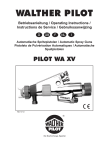
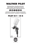
Operating instructions
Model WA 80 Type 20 380
Die Beschichtungs-Experten
Contents
1
1.1
1.2
General
Proper use
Improper use
2
Technical description
3
Safety
4
4.1
4.2
4.3
Using the spray gun
Connections for control air, atomising air and material
Spraying a test pattern
Changing the spray pattern
5
Parts list
6
Exploded diagram
7
7.4
Re-tooling
Distributor
Changing
Changing
Changing
8
Technical data
9
Cleaning and maintenance
10
Troubleshooting
11
EC Conformity Declaration
7.1
7.2
7.3
the spray gun
Gone
the material nozzle
the material needle
the needle seal
Please note our terms of sale and delivery.
Issue: 03.2000
General
11
Proper use
The automatic spray gun must be used only tor processing sprayable materials in tubes
and cavities. in particular:
lacquers and paints
grease, oil and anti-corrosion agents
adhesives, grease, oil and anti-corrosion
ceramic glazes
stains
agents
If you intend to spray materials that are not listed here, please contact WAL THER Spritzund Lackiersysteme GmbH, Wuppertal.
The sprayable materials must be sprayed only on workpieces
The temperature
or objects.
of the material to be sprayed must not exceed 80.C
The model PILOT WA 20 380 is not a hand-held spray gun and must therefore be
mounted in a suitable bracket.
Proper use of the spray gun also includes the fact that you have read, understood end
observed eIl information, advice end safety requirements presented in this instruction
manual.
1.2
Im proper use
The spray gun must not be used in any other way than as described above ih the section
"Proper use".
Any other use is im proper.
Improper use includes:
spraying materials onto persons or an im als
sprayinQ liquid nitroaen
2
Technical description
The model PILOT WA 20 380 is operated automatically by compressed air and is
controlled via 3/2-way control valves. Hand-operated, toot-operated or solenoid-valv
operated valves can be used tor this purpose.
First, the atomising air is introduced bya 3/2-way valve.
Then, the 3/2-way control valve required tor the control air is actuated.
The compressed air flowing into the cylinder chamber moves the control piston and
opens the material teed.
If the control air is interrupted by the 3/2-way valve, the compressed air in the cylindel
chamber is allowed to escape. The spring pressure of the piston spring shuts off the
material feed to the material nozzle.
After this, the atomising air is switched off by the 3/2-way valve.
The spray gun works with the equal pressure method. This means that the atomising c
pressure and the material pressure must be almost the same.
All parts which are in contact with the material are made of corrosion-free stainless ste
3
.
.
Safety
,
The spray gun must be used only by trained and qualified persons.
All relevant rules of safety and workers' safety regulations applicable in the countr)
or area of use must be fully observed.
Observe the instructions given by the manufacturers of the spraying material and tl
cleaning agents with regard to safety and proper use.
Use the spray gun only in well-ventilated rooms. Fire, naked flames and smoking a
prohibited within the working area.
Always wear the regulation breathing masks, protective clothing and hearing
protection when using the spray gun.
Exhaust air which contains particles must be kept away tram the working area and
operating personnei. Make sure that adequate exhaust extraction is provided.
Wlien spraying materials, keep your hands and other parts of the body away tram
the pressurised nozzle of the spray gun.
00 not direct the spray gun at persons or animals.
Before carrying out maintenance or servicing, ensure that the air and material feed 1
the spray gun have been de-pressurised.
Only those air hoses which h.ave a total electric leakage resistance of <100 million
ohms must be used.
After carrying out assembly and maintenance work, ensure that all nuts, bolts and
screw connections have been fully tightened.
Use only original spare parts, sinGe WAL THER can only guarantee safe and faultfree operation tor original parts.
For further information on the safe use of spraying equipment,
Spritz- und Lackiersysteme GmbH, Wuppertal.
please contact WAL THER
4
Using the spray gun
Before using the spray gun, ensure that the following conditions apply:
The control air pressure is applied to the spray gun
. The atomising air pressure is applied to the spray gun
. The material pressure is applied to the spray gun
.
4.1 Connections tor control air, atomising air and material
,
Connectthe controlair connector(via the 3/2-wayvalve)to the spraygun."ST"and
set the controlair pressure(min.4.5 bar).
Connectthe atomisingair connectorto the air hose (filteredcompressedair supply)
and to the atomisingair connections"SP".
Switch on the compressed air and set the required atomising air pressure at the
reducing valve (max. 6 bar).
Fill the pressurepot with the materialto be sprayedand Glosethe lid.
Connectthe materialfeed hoseto the pressurepot or the pump and to the material
connection"M". Set the requiredmaterialpressure(max.6 bar).
Openthe materialvalve on the pressurepot.
4.2 Spraying a test pattern
A test spray pattern should always be made whenever:
. the spray gun is used tor the first time
. the spraying material is changed
. the spray gun has been disassembled tor maintenance or servicing.
The test pattern can be sprayed on a test workpiece, panel, cardboard or paper.
4.3 Changing the spray pattern
The diameter of the atomising GOne can be varied by changing the atomising air.
The material flow rate is determined by the material pressure and the diameter of the
material nozzle.
The spray gun can be used for coating tubes with an inner diameter of up to approx.
500 mm.
0
W
M
0
N
<{
~
~
~
~
0..
Q)
E
10
Z
Qj
.c
::1
c:
E
t
ca
Q.
E
Cl)
:!:
Q)
E
ro
z
'Q)
.0
E
::J
C
t
ro
~
E
~
>'0
0
.0::
IU
Q)
Q)
...
-
'"
Q)
GI
GI
"'
.'-
- -ro-CI)
t:.0
c.
0
Ii)N
Q)
0).t:.t:
-
O.t:
t:
'-
'0
C)u
0
:5:
Q)
'-
u
cn
cn
"a3
~
CO""
0>
.- c.
Ii)
Ii)
t:c.cn.t:~
Ii)
C)
Q)
C
Co
Ii)
-0
QJ
Co
~ .-g>
QJ ~
!2"
-2~CI!
QJQJ~
.Qo-U
Ii)
X cn
Gl
m
ro
::J .- cn-ro .0
-t:c.::Jt:0)
cn.o 0 .-t:
""
C
'-
E .- 0
c. lUcn I Q)
GI"".cn'-
0
C")OM","~C")Ii)C")C")C")
00.0000000
00.0000000
~<DNC")~I'-NNOO","
ON~ONO~OO.Ii)
CX)o>a~N
ONOOOOOOOOO
C")NMC")~C")C")C")C")C")
OaJOOaJOOOOO
NONNONNNNN
»»»»»
Mvln<D
~~~~~~~NNN
CI! ::J
QJ
u"5
'5.
QJ~
QJ
> N
N
QJO
-u;C
-0
QJ,~
.Qo-~-
U.-
Cl!U+-'+-'UQ)
CI! Q) 'c;
-
C
(1)1"""'"
'-
>C)QJ"iiC)QJC
QJ
C
0
U
CQJ
-
::J
QJ
.QQJ.-c'--
":
(1)0-'ffi 0 :c
(l)CI!'E 0 .r:
QJ 'ffi
o-o-CI!_
:c
'in E D- C
Q)
(")(")~(")(")~(")(")(")(")(")o
0000.0000000
0000.0000000
~(,,)(")N\l)O.qo(,,)O~.qoM
OOMOONO~~~O~
COCOMCOtOMCOOOOL()\l)
.qo.qoO.qo.qoO.qoOOOOOOOO
~~~~~~~(,,)(,,)(,,)(,,)M
000)000)000000
(")(")0
(")MO(")NNNNN
»»»»»»
.-NM"f"InCOt-(X)O)O'-N
C>
C
Q)
t13
.t::
Q)
~
Co
~
"C
"0
.Q
.E
"C
Q)
C
CI)
Co
.t::
t13
t:
Co
t13-
=..-i.
t13
J::CI)
c"'"
"C
Q)Co
u
0
E
CI)
ro
Q)
C
.-
8
E~
'Q)
Q)t:
s~
C)
t::
'5
t::
0
CUJ
Q)
t:
0
Co)
Q)
:5
~E
~E
Q)1l1
UJ...:
1\1
UJ
t::
.Q
UJ
t::
Q)
E
~
~o
C.
.'UJ ..
t'I\I~
C-Q)
C)E
t:: 1\1
.-= '5
Q)
"U
'0
t::
Q)
J::
S
.
.
~
on-
~ ---rn
I
I
111
r
"11
o.
'"
~-
~I
I
~-..
~
.I
:"4
I=~./.
t\
I
I
4;'"
r
L
I
a!--~
~
-=t=-~
~~
I
eS
N
\
7
Re-tooling the spray gun
Before re-tooling the spray gun, always ensure that the air supply and material suPI
the spray gun have been interrupted.
The combination ot air cap. material nozzle and needle tor a certain spraying materl
torms a specially matched unit - the nozzle assembly.
Always exchange the complete nozzle assembly in order to maintain the desired Spl
pattern quality.
7.1 Changing the distributor cone
1.
2,
Unscrew the distributor cone with a screw driver.
Installation takes place in reverse order.
7.2 Changing the material nozzle
1.
2.
3.
4.
5.
6.
7.
Unscrew the distributor cone with a screw driver.
Release the air cap nut.
Unscrew the complete unit, air tube and air sleeve SW 14
Unscrew the air tube from~he air sleeve SW 13/ SW 14
Unscrew the material tube from the air sleeve SW 9 /13
Unscrew the material nozzle SW 3
Installation takes place in reverse order.
7.3 Changing the material needle
1.
2.
3.
4.
5.
Unscrew the spring bushing from the body.
Remove the piston spring and pull out the piston together with the material
needle.
Unscrew the material needle from the piston.
Installation takes place in reverse order.
The distance between the tip of the material needle and the piston should be s
. at 62.5 mm
.
7.4 Changing the needle seal
1.
2
3.
4
5.
Remove the material needle, as described under 7.3.
Continue as described under 7.2.
Unscrew the packing scrßw tram the body.
Withdraw the needle seal.
Installation takes plaGe in reverse order.
8
Technical data
Weight:
144 9
Connections:
Atomising air:
Control air:
Material feed:
2x PK 4
PK3
PK4
Pressure range:
Control air pressure:
min. 4.5 bar
Material pressure:
max. 6 bar
Atomising air pressure: max. 6 bar
9
Air consumption at:
1
2
3
4
5
6
bar
bar
bar
bar
bar
bar
atomising
atomising
atomising
atomising
atomising
atomising
air
air
air
air
air
air
press.
press.
press.
press.
press.
press.
1.2 m3/hr
1.8 m3Ihr
2.4 m3Ihr
3.0 m3/hr
3.6 m3/hr
4.8 m3Ihr
The noise level is 83 dB (A) ,
Technical data are subjectto change.
Cleaning and maintenance
To ensure that the spray gun functions properfy and to maximise its service life, the
spray gun must be maintained, cleaned and lubricated regularfy.
Before carrying out any maintenance, ensure that the control air and atomising air as
weil as the material feed are de-pressurised.
Cleaning should be carried out after every colour and material change or according
to the degree of contamination.
For cleaning the spray gun, use only those cleaning agents that are specified by the
material manufacturer and ensure that they do not contain any of the following
components:
halogenated hydrocarbons, e.g. 1, 1,1-trichloroethane,
methylene chloride,
acids or acidic cleaning agents,
paint strippers,
regenerated solvents (cleaning thinners).
Never immerse the whole spray gun in solvent or cleaning agent, as this could harm
the correct functioning of the gun.
00 not use sharp or hard objects to clean the spray gun, as this might cause damage
to precision parts and impair the spFaying result.
WAL THER PILOT cannot accept any liability tor damage caused by improper
treatment of the spray gun.
Troubleshooting
Fault
Cause
Remedy
Spray fan too wide in the
I
ISet spray fan wider
middle
I
I Spray
fan
too
wide
at the
I Set a rounder fan shape
IAnrl~
Increase atomising air
nrp~~llr~
Reduce atomising air pressure
Increase material pressure
I Reduceatomisingair
In,.,r""'~" m~to..i~1 nr""~llr"
I Reduce material pressure
Increase atomising air
.
nr~ssure
rGundr~
I
Material needle or nozzle
dirty
Remove and clean
Material needle or nozzle
Replace
damaged
Gun does not open
I
Control air pressure too
low
Increase control air pressure
to min. 4.5 bar
Insufficient material in
container
Fill up with material (see
instructions tram material
manufacturer)
O-ring Item 11 damaged
Replace
WALTHER
Spritz- und Lackiersysteme
Kärtner Str. 18-30
Tel.: 0202/787-0
Fax: 0202/787-217
EC Confon11ity Declaration
We hereby declare thaI the spray gun
.
model: Walther PILOT WA Block80
type designation
WA 20 380
.
year of first manufacture:
1999
.specified use:
processing sprayable materials
.fabrication
number: see side of packaging
as describedin the accompanyingdocumentation,is in full accordancewith the followingguidelines:
EC machine guideline 89/392/EWG with amendments 91/368/EWG,
93/44/EWG and 93/68/EWG.
Harmonised
standards
applied in the versions valid at the time of issue, in particular:
EN 292 (safety of machines)
prEN 1953 (spraying equipment
tor coating materials)
Note:
This machine is not subject to the requirements of Appendix IV for machines representing a special
danger in accordance with Directive 89/392/EWG.
Records are therefore kept on file in Dur company.
Name: Winfried Wiese
Position in the company:
Plant Manager
The WALTHER PILOT Product Range
..
..
Manual spray guns
Automatic spray guns
HVLP spray guns
Two-component spray guns
. Pressure pots
. Pressureless containers
. Agitator systems
. Airless equipment and fluid pumps
. Material circulation systems
. Two-pack systems
. Marking equipment
..
.
.
.
.
Combined-spraying and drying booths
Exhaust extraction systems with dry filtering
Exhaust extraction systems with wet filtering
Powder spraying stands
Powder spraying equipment
Adhesive spraying systems
.
Dryers
Air supply systems
Breathing masks, breathing equipment and accessories
WAL THER Spritz- und Lackiersysteme Kärtnerstr. 18-30
0-42347 Wuppertal Tel. 0202 787-0 Fax 0202787217
http://www.walther-pilot.de E-mail: info@walther-pilot
~~;~.'
Die Beschichtungs-Experten
Issue: 03.2000