1
Contents
HP E8491B IEEE 1394 PC Link to VXI Configuration and User’s Guide
Edition 2
Safety Symbols ............................................................................................................. 6
WARNINGS ................................................................................................................. 6
Declaration of Conformity............................................................................................ 7
Reader Comment Sheet ................................................................................................ 9
Chapter 1
Introduction .................................................................................................................. 11
Using the IEEE 1394 Serial Bus in VXI Systems ...................................................... 11
Component Overview ......................................................................................... 11
The HP E8491B PC Link to VXI Interconnect ............................................ 11
The OHCI-Compatible PCI-to-IEEE 1394 Host Adapter ............................ 11
The HP I/O Libraries .................................................................................... 11
Using this Manual .............................................................................................. 11
Chapter 2: Interface Installation and Configuration ..................................... 11
Chapter 3: VXI Programming Using the IEEE 1394 Serial Bus .................. 12
Chapter 4: IEEE 1394 Fundamentals and Interface Overview ..................... 12
Appendix A: Specifications .......................................................................... 12
Appendix B: Editing the HP E8491B Resource Manager Configuration .... 12
Additional Information ........................................................................................ 12
Chapter 2
Interface Installation and Configuration ................................................................... 13
Using this Chapter ...................................................................................................... 13
Step 1: Installing the IEEE 1394Host Adapter .................................................... 13
Where to go Next .......................................................................................... 17
Step 2: Installing the HP E8491B Interconnect .................................................. 17
Alternate Configurations .............................................................................. 19
Where to go Next .......................................................................................... 20
Step 3: Installing VXI Instruments ...................................................................... 20
Installing C-size Instruments ........................................................................ 21
Installing A- and B-size Instruments ............................................................ 22
Step 4: Installing the HP I/O Libraries ................................................................ 24
Configuring the HP E8491B Interconnect .................................................... 24
Editing the HP E8491B Configuration ......................................................... 26
Editing the HP E8491B Configuration on Windows 95 Platforms .............. 27
Step 5: Installing HP VXIplug&play Instrument Drivers ................................... 28
Step 6. Verifying the Installation ........................................................................ 29
Using Instrument Soft Front Panels .............................................................. 29
Viewing the Resource Manager Output ....................................................... 30
Troubleshooting Installation Problems ............................................................... 33
Running the Resource Manager .......................................................................... 33
Contents
1
Chapter 3
VXI Programming Using the IEEE 1394 Serial Bus ................................................ 35
Using this Chapter ...................................................................................................... 35
Programming Register-Based and Message-Based VXI Instruments ................. 35
Opening Instrument Sessions .............................................................................. 35
Optimizing Programs .......................................................................................... 36
Block Data Transfers .................................................................................... 36
Block Transfers using HP VXIplug&play Drivers ....................................... 37
Block Transfers using HP VISA ................................................................... 40
HP E8491B Triggering ........................................................................................ 43
Using Triggers .............................................................................................. 43
Configuring the E8491B Trig In and Trig Out Ports .................................... 44
Triggering Example ...................................................................................... 45
Trigger Pull Up ............................................................................................. 47
Using HP E8491B Shared Memory .................................................................... 47
Locating E8491B Shared Memory ............................................................... 47
Example Programs .............................................................................................. 49
Storing Readings in Shared Memory - HP VISA Example .......................... 50
Storing Readings in Shared Memory - SICL Example ................................ 54
Chapter 4
IEEE 1394 Fundamentals and Interface Overview .................................................. 57
Using this Chapter ...................................................................................................... 57
IEEE 1394 Topology and Terminology .............................................................. 57
Features of the IEEE 1394 Bus ..................................................................... 58
Optimizing the Configuration ....................................................................... 59
IEEE 1394 Data Transfer Protocol ...................................................................... 59
Asynchronous Data Transfers ....................................................................... 60
Fair Arbitration Protocol ............................................................................... 60
VXI Data Transfers ....................................................................................... 60
OHCI-Compatible Host Adapter and Interface Cable ........................................ 61
The HP E8491B PC to VXI Interconnect ........................................................... 62
Using the HP E8491B with the HP E1406 Command Module .................... 64
The HP I/O Libraries ........................................................................................... 64
Appendix A
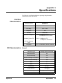
Specifications ................................................................................................................ 65
Interface Characteristics ...................................................................................... 65
VXI Characteristics ............................................................................................. 65
General .......................................................................................................... 65
CLK 10 ......................................................................................................... 66
External Trigger Input .................................................................................. 66
External Trigger Output ................................................................................ 66
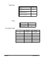
Trigger Delays .............................................................................................. 67
Cooling ......................................................................................................... 67
Power Supply Loading ................................................................................. 67
2
Contents
Appendix B
Editing the HP E8491B Resource Manager Configuration ..................................... 69
Introduction................................................................................................................. 69
Configuration File Overview .............................................................................. 69
The names.cf Configuration File .................................................................. 72
The oride.cf Configuration File .................................................................... 72
The vmedev.cf Configuration File ................................................................ 72
The cmdrsrvt.cf Configuration File .............................................................. 72
The dynamic.cf Configuration File ............................................................... 72
The irq.cf Configuration File ........................................................................ 73
The ttltrig.cf Configuration File ................................................................... 73
The vximanuf.cf Configuration File ............................................................. 73
The vximodel.cf Configuration File ............................................................. 73
Utility Function Overview .................................................................................. 73
Using ivxisc .................................................................................................. 73
Using iclear ................................................................................................... 75
Index ................................................................................................................................ 77
Contents
3
4
Contents
HEWLETT-PACKARD WARRANTY STATEMENT
HP PRODUCT:
HP E8491B IEEE 1394 PC LINK to VXI
DURATION OF WARRANTY: 3 years
1. HP warrants HP hardware, accessories and supplies against defects in materials and workmanship for the period specified above. If
HP receives notice of such defects during the warranty period, HP will, at its option, either repair or replace products which prove to be
defective. Replacement products may be either new or like-new.
2. HP warrants that HP software will not fail to execute its programming instructions, for the period specified above, due to defects in
material and workmanship when properly installed and used. If HP receives notice of such defects during the warranty period, HP will
replace software media which does not execute its programming instructions due to such defects.
3. HP does not warrant that the operation of HP products will be interrupted or error free. If HP is unable, within a reasonable time, to
repair or replace any product to a condition as warranted, customer will be entitled to a refund of the purchase price upon prompt return
of the product.
4. HP products may contain remanufactured parts equivalent to new in performance or may have been subject to incidental use.
5. The warranty period begins on the date of delivery or on the date of installation if installed by HP. If customer schedules or delays HP
installation more than 30 days after delivery, warranty begins on the 31st day from delivery.
6. Warranty does not apply to defects resulting from (a) improper or inadequate maintenance or calibration, (b) software, interfacing, parts
or supplies not supplied by HP, (c) unauthorized modification or misuse, (d) operation outside of the published environmental
specifications for the product, or (e) improper site preparation or maintenance.
7. TO THE EXTENT ALLOWED BY LOCAL LAW, THE ABOVE WARRANTIES ARE EXCLUSIVE AND NO OTHER
WARRANTY OR CONDITION, WHETHER WRITTEN OR ORAL, IS EXPRESSED OR IMPLIED AND HP SPECIFICALLY
DISCLAIMS ANY IMPLIED WARRANTY OR CONDITIONS OF MERCHANTABILITY, SATISFACTORY QUALITY, AND
FITNESS FOR A PARTICULAR PURPOSE.
8. HP will be liable for damage to tangible property per incident up to the greater of $300,000 or the actual amount paid for the product
that is the subject of the claim, and for damages for bodily injury or death, to the extent that all such damages are determined by a court
of competent jurisdiction to have been directly caused by a defective HP product.
9. TO THE EXTENT ALLOWED BY LOCAL LAW, THE REMEDIES IN THIS WARRANTY STATEMENT ARE CUSTOMER’S
SOLE AND EXLUSIVE REMEDIES. EXCEPT AS INDICATED ABOVE, IN NO EVENT WILL HP OR ITS SUPPLIERS BE
LIABLE FOR LOSS OF DATA OR FOR DIRECT, SPECIAL, INCIDENTAL, CONSEQUENTIAL (INCLUDING LOST PROFIT OR
DATA), OR OTHER DAMAGE, WHETHER BASED IN CONTRACT, TORT, OR OTHERWISE.
FOR CONSUMER TRANSACTIONS IN AUSTRALIA AND NEW ZEALAND: THE WARRANTY TERMS CONTAINED IN THIS
STATEMENT, EXCEPT TO THE EXTENT LAWFULLY PERMITTED, DO NOT EXCLUDE, RESTRICT OR MODIFY AND ARE
IN ADDITION TO THE MANDATORY STATUTORY RIGHTS APPLICABLE TO THE SALE OF THIS PRODUCT TO YOU.
U.S. Government Restricted Rights
The Software and Documentation have been developed entirely at private expense. They are delivered and licensed as "commercial
computer software" as defined in DFARS 252.227- 7013 (Oct 1988), DFARS 252.211-7015 (May 1991) or DFARS 252.227-7014 (Jun
1995), as a "commercial item" as defined in FAR 2.101(a), or as "Restricted computer software" as defined in FAR 52.227-19 (Jun
1987)(or any equivalent agency regulation or contract clause), whichever is applicable. You have only those rights provided for such
Software and Documentation by the applicable FAR or DFARS clause or the HP standard software agreement for the product involved.
HP E8491B IEEE 1394 PC Link to VXI Configuration and User’s Guide
Edition 2
Copyright © 1999 Hewlett-Packard Company. All Rights Reserved.
5
Documentation History
All Editions and Updates of this manual and their creation date are listed below. The first Edition of the manual is Edition 1. The Edition
number increments by 1 whenever the manual is revised. Updates, which are issued between Editions, contain replacement pages to
correct or add additional information to the current Edition of the manual. Whenever a new Edition is created, it will contain all of the
Update information for the previous Edition. Each new Edition or Update also includes a revised copy of this documentation history page.
Edition 1 . . . . . . . . . . . . . . . . . . . . . . . . . . . . . . . . . . . . . . . . . . . . . . . .June 1998
Edition 2 . . . . . . . . . . . . . . . . . . . . . . . . . . . . . . . . . . . . . . . . . . . . . . . .June 1999
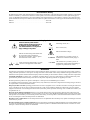
Safety Symbols
Instruction manual symbol affixed to
product. Indicates that the user must refer to
the manual for specific WARNING or
CAUTION information to avoid personal
injury or damage to the product.
Alternating current (AC)
Direct current (DC).
Indicates hazardous voltages.
Indicates the field wiring terminal that must
be connected to earth ground before
operating the equipment—protects against
electrical shock in case of fault.
or
Frame or chassis ground terminal—typically
connects to the equipment's metal frame.
Calls attention to a procedure, practice, or
WARNING condition that could cause bodily injury or
death.
Calls attention to a procedure, practice, or
CAUTION condition that could possibly cause damage to
equipment or permanent loss of data.
WARNINGS
The following general safety precautions must be observed during all phases of operation, service, and repair of this product. Failure to
comply with these precautions or with specific warnings elsewhere in this manual violates safety standards of design, manufacture, and
intended use of the product. Hewlett-Packard Company assumes no liability for the customer's failure to comply with these requirements.
Ground the equipment: For Safety Class 1 equipment (equipment having a protective earth terminal), an uninterruptible safety earth
ground must be provided from the mains power source to the product input wiring terminals or supplied power cable.
DO NOT operate the product in an explosive atmosphere or in the presence of flammable gases or fumes.
For continued protection against fire, replace the line fuse(s) only with fuse(s) of the same voltage and current rating and type. DO NOT
use repaired fuses or short-circuited fuse holders.
Keep away from live circuits: Operating personnel must not remove equipment covers or shields. Procedures involving the removal of
covers or shields are for use by service-trained personnel only. Under certain conditions, dangerous voltages may exist even with the
equipment switched off. To avoid dangerous electrical shock, DO NOT perform procedures involving cover or shield removal unless you
are qualified to do so.
DO NOT operate damaged equipment: Whenever it is possible that the safety protection features built into this product have been
impaired, either through physical damage, excessive moisture, or any other reason, REMOVE POWER and do not use the product until
safe operation can be verified by service-trained personnel. If necessary, return the product to a Hewlett-Packard Sales and Service Office
for service and repair to ensure that safety features are maintained.
DO NOT service or adjust alone: Do not attempt internal service or adjustment unless another person, capable of rendering first aid and
resuscitation, is present.
DO NOT substitute parts or modify equipment: Because of the danger of introducing additional hazards, do not install substitute parts
or perform any unauthorized modification to the product. Return the product to a Hewlett-Packard Sales and Service Office for service
and repair to ensure that safety features are maintained.
6
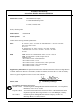
Declaration of Conformity
according to ISO/IEC Guide 22 and EN 45014
Manufacturer’s Name:
Hewlett-Packard Company
Loveland Manufacturing Center
Manufacturer’s Address:
815 14th Street S.W.
Loveland, Colorado 80537
declares, that the product:
Product Name:
IEEE 1394 PC Link to VXI
Model Number:
HP E8491B
Product Options:
All
conforms to the following Product Specifications:
Safety:
IEC 61010-1 (1990) + A1:1992 + A2:1995/EN61010-1 + A1:1993 + A2:1995
CSA C22.2 #1010.1:1992
UL 3111-1
IEC 60950:1991 + A1:1992 + A2:1993 + A3:1994 + A4:1996/
EN60950:1992 + A1:1993 + A2:1993 + A3:1995 + A4:1997
UL 1950
EMC:
CISPR 22:1993 + A1:1995/EN55022:1992 + A1:1995 : Class A
CISPR 11:1990/EN55011 (1991): Group1 Class A
EN50082-1:1997
IEC 61000-4-2:1995/: 4kVCD, 8kVAD
IEC 61000-4-3:1995/: 3 V/m
IEC 61000-4-4:1995/: 1kV Power Line, 0.5kV Signal Lines
IEC 61000-4-5:1995/: 1kV, CM 0.5 kV DM
IEC 61000-4-6:1996/: 3 Vrms
IEC 61000-4-11:1994/: 30%, 10ms 80%, 100ms
Supplementary Information: The product herewith complies with the requirements of the Low Voltage Directive
73/23/EEC and the EMC Directive 89/336/EEC (inclusive 93/68/EEC) and carries the "CE" mark accordingly.
Tested in a typical configuration in an HP C-Size VXI mainframe.
Jim White, QA Manager
March 5, 1999
For Compliance Information ONLY, contact:
Australian Contact:
European Contact:
USA Contact:
Product Regulations Manager, Hewlett-Packard Australia Ltd., 31-41 Joseph Street,
Blackburn, Victoria 3130, Australia
Your local Hewlett-Packard Sales and Service Office or Hewlett-Packard GmbH,
Department HQ-TRE, Herrenberger Straße 130, D-71034 Böblingen, Germany
(FAX +49-7031-14-3143)
Product Regulations Manager, Hewlett-Packard Company, P.O. Box 301,
Mail Stop BU212, Loveland, CO 80537
7
Notes:
8
Please fold and tape for mailing
Reader Comment Sheet
HP E8491B IEEE 1394 PC Link to VXI Configuration and User’s Guide
Edition 2
You can help us improve our manuals by sharing your comments and suggestions. In appreciation of your time, we will
enter you in a quarterly drawing for a Hewlett-Packard Palmtop Personal Computer (U.S. government employees
are not eligible for the drawing).
Your Name
City, State/Province
Company Name
Country
Job Title
Zip/Postal Code
Address
Telephone Number with Area Code
Please list the system controller, operating system, programming language, and plug-in modules you are using.
fold here
cut along this line
NO POSTAGE
NECESSARY
IF MAILED
IN THE
UNITED STATES
BUSINESS REPLY MAIL
FIRST CLASS
PERMIT NO. 37
LOVELAND, CO
POSTAGE WILL BE PAID BY ADDRESSEE
HEWLETT-PACKARD COMPANY
Measurement Systems Division
Learning Products Department
P.O. Box 301
Loveland, CO 80539-9984
fold here
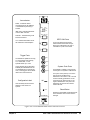
Please pencil-in one circle for each statement below:
• The documentation is well organized.
• Instructions are easy to understand.
• The documentation is clearly written.
• Examples are clear and useful.
• Illustrations are clear and helpful.
• The documentation meets my overall expectations.
Please write any comments or suggestions below–be specific.
Disagree
O
O
O
O
O
O
Agree
O
O
O
O
O
O
O
O
O
O
O
O
O
O
O
O
O
O
O
O
O
O
O
O
Chapter 1
Introduction
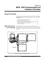
Using the IEEE 1394 Serial Bus in VXI Systems
The IEEE 1394 Serial Bus (FireWire) is a high-speed bus that has been
implemented as an I/O interface between external PCs and HP VXI systems.
The bus links the PC backplane to the VXI mainframe backplane. This
manual describes the implementation, configuration, and use of this
interface.
Component
Overview
Implementation of the IEEE 1394 serial bus as an I/O interface for HP VXI
systems is provided through three components and two operating systems:
• HP E8491B PC Link to VXI Interconnect
• OHCI-compatible PCI-to-IEEE 1394 Host Adapter
• HP I/O Libraries
• WIN 95 and WIN NT operating systems
The HP E8491B PC Link
to VXI Interconnect
The HP E8491B is the VXI hardware that links the VXI mainframe
backplane to the IEEE 1394 serial bus. The E8491B is a 1-slot, C-size,
message-based device that is installed in mainframe slot 0.
The OHCI-Compatible
PCI-to-IEEE 1394 Host
Adapter
The OHCI PCI-to-1394 Host Adapter card is installed in the PC and links
the computer’s (PCI) backplane to the IEEE 1394 bus. The OHCI adapter
has three external IEEE 1394 ports and can support up to 16 HP E8491Bs.
The HP I/O Libraries
The HP I/O Libraries provide the HP VISA and HP SICL drivers required
to use the HP E8491B. Included with the libraries are the drivers for the
OHCI-compatible host adapter.
Using this Manual
This manual is organized to help you install, configure, and begin using the
IEEE 1394 serial bus as quickly and efficiently as possible. The following
information outlines the contents of the other chapters, and identifies the
areas of programming a VXI system that are NOT covered in this manual.
Chapter 2: Interface
Installation and
Configuration
Chapter 1
This chapter contains information on installing the HP E8491B hardware
and its drivers (the HP I/O Libraries). Also included is information on
installing VXI instruments, installing HP VXIplug&play drivers, and on
verifying the system.
Introduction
11
Chapter 3: VXI
Programming Using the
IEEE 1394 Serial Bus
This chapter contains the information necessary to begin communicating
with VXI instruments through the HP E8491B and IEEE 1394 serial bus.
The chapter contains information on optimizing system performance using
block data transfers, and also covers triggering and using HP E8491B shared
memory.
Chapter 4: IEEE 1394
Fundamentals and
Interface Overview
This chapter describes the IEEE 1394 serial bus and how it is implemented
in HP VXI systems. It defines the bus terminology and data transfer
protocol.
Appendix A:
Specifications
Appendix A contains the operating and performance specifications of the
HP E8491B.
Appendix B: Editing the
HP E8491B Resource
Manager Configuration
Appendix B contains information on editing your VXI system configuration
as set by the resource manager. It describes selected configuration files and
utility functions used to view and modify your configuration.
Additional
Information
Programming the HP E8491B is through HP VISA and HP SICL functions.
Although this manual identifies the specific functions used, you will need to
refer to the HP VISA and HP SICL manuals for detailed information.
Also, included with the HP I/O Libraries is the utility ‘I_O Config’. This
utility is used to configure the HP E8491B and has a help file associated with
it.
Note
12
Introduction
Pop-up or pull-down menus displayed by the HP I/O Libraries software
will show I/O Libraries as “I_O Libraries” and I/O Config as “I_O Config”
because the “/” cannot be displayed. The “/” character is therefore replaced
by the underscore character.
Chapter 1
Chapter 2
Interface Installation and Configuration
Using this Chapter
This chapter contains information necessary to install and configure the
IEEE 1394 host adapter (if required) and the HP E8491B interconnect. The
installation sequence and other topics covered in this chapter are as follows:
• Step 1: Installing the IEEE 1394 Host Adapter . . . . . . . . . .
• Step 2: Installing the HP E8491B Interconnect . . . . . . . . . .
• Step 3: Installing VXI Instruments . . . . . . . . . . . . . . . . . . . .
• Step 4: Installing the HP I/O Libraries . . . . . . . . . . . . . . . . .
• Step 5: Installing HP VXIplug&play Instrument Drivers. . .
• Step6: Verifying the Installation . . . . . . . . . . . . . . . . . . . . . .
• Running the Resource Manager . . . . . . . . . . . . . . . . . . . . . .
Step 1: Installing
the IEEE 1394
Host Adapter
WARNING
Note
Chapter 2
13
17
20
24
28
29
33
The IEEE 1394 adapter shipped as Option 001 to the HP E8491B is an
OHCI-compatible PCI-to-IEEE 1394 Host Adapter. Included with the
adapter is a cable for powering IEEE 1394 devices and a 4.5m interface
cable.
Refer to your computer’s documentation for specific
instructions about the installation of PCI adapters.
If your personal computer (PC) currently has a Solectron OHCI403 PCI-toIEEE 1394 host adapter, a later version OHCI-compatible PCI-to-IEEE
1394 host adapter or a built-in IEEE 1394 port, proceed to Step 2: Installing
the HP E8491 Interconnect.
Interface Installation and Configuration
13
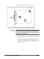
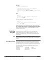
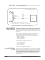
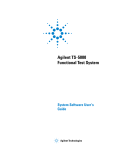
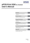
The layout of a typical host adapter is shown in Figure 2-1.
12 VDC
Power Connector
External
IEEE 1394
Connectors
Figure 2-1. Layout of a Typical OHCI-Compatible PCI-to-IEEE 1394 Host Adapter.
WARNING
Turn off and disconnect the power to your computer and to any
peripheral devices before installing the host adapter. Refer to
your computer’s documentation for specific instructions about
the installation of PCI adapters.
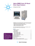
1. Remove the computer chassis cover to expose the expansion slots and
external access covers.
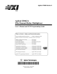
2. Locate an unused, unobstructed PCI bus expansion slot (Figure 2-2)
that supports bus mastering. (PCI bus slots are usually white or
ivory.) See your computer documentation to determine if the PCI slot
supports bus mastering.
14
Interface Installation and Configuration
Chapter 2
PCI expansion slots
(usually white or ivory)
shared slot
Figure 2-2. Locating a PCI bus Expansion Slot.
Note
Many computer PCI systems have one pair of ISA and PCI slots close to
each other. This saves space and allows you to install either an ISA card or
a PCI card in the slot pair.
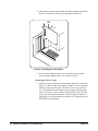
3. Remove the corresponding expansion slot cover from the computer
chassis (Figure 2-3).
expansion slot cover
Figure 2-3. Removing the PC Expansion Slot Cover.
Chapter 2
Interface Installation and Configuration
15
4. Align the bus contacts on the bottom of the host adapter with the PCI
bus slot. Carefully, but firmly, press the adapter into the slot.
Host
Adapter
Figure 2-4. Installing the Host Adapter.
5. Secure the host adapter bracket to the computer chassis with the
screw from the expansion slot cover removed in step C.
Connecting the Power Cable
6. Connect the power cable between the adapter and the PC as shown in
Figure 2-5. This provides power from the adapter to devices along the
interface via the interface cable. This allows you to cycle power on
any VXI mainframe in multi-frame systems without affecting other
frames. The power is also available to other IEEE 1394 devices that
may be part of the interface network. The host adapter is capable of
supplying 12V with a maximum current draw of 0.5 amps total to all
three IEEE 1394 connectors.
16
Interface Installation and Configuration
Chapter 2
Host
Adapter
12V DC
Power
Connector
Power In
(From System
Power Supply)
Power Out
(To Disk Drives)
Figure 2-5. Connecting the Power Cable Between the PC and the Host Adapter.
7. Replace the computer cover. Connect one end of the interface cable to
either adapter external connector.
Where to go Next
• If you are installing the IEEE 1394 interface for the first time:
Continue with “Step 2: Installing the HP E8491B Interconnect.”
• If the E8491B and your VXI instruments are already installed:
Proceed to “Step 4: Installing the HP I/O Libraries.” Note that the
HP I/O Libraries contain the OHCI-compatible host adapter drivers.
Note
Step 2: Installing
the HP E8491B
Interconnect
Refer to Chapter 4: IEEE 1394 Fundamentals and Interface Overview for
more information on the OHCI-compatible PCI-to-IEEE 1394 host adapter.
The HP E8491B interconnect links the IEEE 1394 bus to the backplane of
the VXI mainframe. The HP E8491B is a C-size device with VXI Resource
Manager and Slot 0 capability.
There are no configuration switches on the HP E8491B. The device’s logical
address is 0 and it provides the system’s resource manager functionality via
software that is part of the HP I/O Libraries. Its VXI servant area is 255,
therefore; it is the interface to all VXI devices with logical addresses
between 1 and 255. The HP E8491B is normally, but not required to be,
installed in mainframe slot 0.
Note
Chapter 2
Refer to “Alternate Configurations” on page 19 for information on using
the HP E8491B with the HP E1406 Command Module and using it in
VXI-MXI systems.
Interface Installation and Configuration
17
1. If power is applied to the VXI mainframe, remove power to the VXI
mainframe and disconnect all power sources that may be applied to
any instruments.
2. Insert the E8491B into mainframe slot 0 by aligning the module with
the guides inside the mainframe (Figure 2-6). Slowly push the module
into the slot until it seats in the backplane connectors. It may be
necessary to pull out (not remove) the retaining screws in order to
seat the device securely in the connectors.
Retaining
Screws
Seat the module by
pushing in the
extraction levers
Extraction
Levers
Slide the module
into the mainframe
until it plugs into the
backplane connectors
Figure 2-6. Installing the HP E8491B in the VXI Mainframe.
3. Tighten the retaining screws on the top and bottom of the module.
Connecting the HP E8491B to the Host Adapter
4. Connect the interface cable from the host adapter to E8491B port A,
B, or C. The ports are identical and unused ports are available to
connect additional E8491Bs and other IEEE 1394 devices in a
daisy-chain or tree configuration (Figure 2-7). Notice that there can
18
Interface Installation and Configuration
Chapter 2
be no closed loops.
DAISY-CHAIN CONFIGURATION
TREE CONFIGURATION
PC
PC
VXI
VXI
VXI
VXI
VXI
*
VXI
VXI
* A second connection creates a closed loop and is not allowed
Figure 2-7. IEEE 1394 Interface Configurations.
I/O performance is impacted slightly by the hardware configuration.The
VXI mainframe with the fewest number of hops (cable links) to the PC has
the highest priority. However, each mainframe has equal access to the bus
during each data transfer interval.
Note
Refer to Chapter 4: IEEE 1394 Fundamentals and Interface Overview for
information on the topology and terms associated with the IEEE 1394 bus.
Alternate Configurations
Certain applications may include the HP E1406A Command Module as an
HP-IB interface to selected instruments. In this configuration, the E8491B
must be the resource manager since its logical address is always 0. It is
generally installed in mainframe slot 0 so that it also provides the system’s
slot 0 functionality.
If you want the E1406 to provide slot 0 functionality in addition to providing
an HP-IB interface, set its configuration as follows:
1. Set the E1406 logical address to a value other than 0.
2. Set the Slot 0 and System Controller switches to “Enable” (default).
3. Set the CLK 10 source to “Internal” (default).
4. Set the VME BTO Disable switch to 0 - Enable (default). Set VME
Chapter 2
Interface Installation and Configuration
19
Bus Timeout (BTO) on the E8491B to ‘Off’ (see “Editing the
HP E8491B Configuration” later in this chapter).
5. Set the E1406 servant area to include the logical addresses of those
instruments it is to control. Note:
E1406 servant area = (E1406 logical address + 1) through
(E1406 logical address + servant area switch setting)
6. Install the E1406 in slot 0.
If the E1406 is not the slot 0 device, its slot 0 functionality must be disabled.
From step 2 above, set the E1406A Slot 0 and System Controller switches
to “Disable”. From step 4, set its VME BTO Disable switch 1 and ensure that
VME Bus Timeout (BTO) on the E8491B is set to ‘On’.
If you are using the E8491B in a configuration with multiple mainframes
linked with VXI-MXI extender cards, the E8491B must be the resource
manager; however, VME Bus Timeout (BTO) must be disabled (off - Step
4 above). Again, the E8491B is generally installed in mainframe slot 0 so
that it also provides the system’s slot 0 functionality. Refer to the MXI
documentation for configuration guidelines based on where the E8491B is
installed.
Where to go Next
• If you are installing the IEEE 1394 interface for the first time:
Continue with “Step 3: Installing VXI Instruments.”
• If your VXI instruments are already installed:
Proceed to “Step 4: Installing the HP I/O Libraries.”
Step 3: Installing
VXI Instruments
20
Generally, any VXI instrument can be installed in any slot other than slot 0.
When installing instruments, notice that the E8491B and the IEEE 1394 bus
do not extend the (VXI) backplane between frames in multi-frame VXI
systems (MXI cards are required). This means that the multimeter and
multiplexers in a VXI scanning multimeter for example, must be installed in
the same mainframe (in adjacent slots). Devices sharing the VXI Local bus
must also be installed in the same mainframe.
Interface Installation and Configuration
Chapter 2
Installing C-size
Instruments
Figure 2-8 shows the installation of C-size instruments.
seat the module by
pushing in the
extraction levers
retaining
screws
extraction
levers
slide the module
into the mainframe
until it plugs into the
backplane connectors
Figure 2-8. Installing C-size Instruments.
Caution
To prevent damage to the VXI instruments being installed,
remove power from the mainframe or set the power switch to
Off or Standby before installing the instruments.
1. Insert the instrument into the mainframe by aligning the instrument
with the card guides inside the mainframe. Slowly push the instrument into the slot until it seats in the backplane connectors. The front
panel of the instrument should be even with the front edges of the
mainframe.
2. Tighten the retaining screws on the top and bottom of the module.
WARNING
Chapter 2
All instruments within the VXI mainframe are grounded through
the mainframe chassis. During installation, tighten the
instruments’ retaining screws to secure the instrument to the
mainframe and to make the ground connection.
Interface Installation and Configuration
21
Installing A- and B-size
Instruments
A- and B-size instruments can also be installed in the mainframe. These
instruments are installed using a module carrier:
• HP E1403C A/B-size Module Carrier extends the P1 connector on
the VXIbus backplane and mounts the (A/B-size) modules flush with
C-size modules. This carrier is recommended for Hewlett-Packard
B-size, slave-only devices which have the P1 connector.
• HP E1407A A/B Module Carrier
extends the P1and P2 connectors
on the VXIbus backplane. This carrier is recommended for B-size,
slave-only devices which have the P1/P2 connectors.
Caution
To prevent damage to the VXI instruments, install the
instruments when the mainframe is turned off.
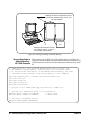
Figure 2-9 shows the installation of a B-size instrument using a module
carrier. The procedure is described in the following three steps.
1. Install the HP E1403 or E1407 A/B-size Module Carrier into the
mainframe. This is done by aligning the top and bottom of the carrier
with the card guides and slowly pushing the carrier into the
mainframe. The front of the carrier should be even with the front
edges of the mainframe.
2. Slide the A- or B-size instrument into the carrier until it connects.
3. Tighten the retaining screws on the top and bottom of the instrument.
WARNING
22
All instruments within the VXI mainframe are grounded through
the mainframe chassis. During installation, tighten the
instruments’ retaining screws to secure the instrument to the
mainframe and to make the ground connection.
Interface Installation and Configuration
Chapter 2
Figure 2-9. Installing A- and B-size VXI Instruments.
Chapter 2
Interface Installation and Configuration
23
Step 4: Installing
the HP I/O Libraries
The HP I/O Libraries CD contains the software required to use the IEEE
1394 interface in a VXI system. It also includes the OHCI-compatible host
adapter drivers.
Note
Refer to Chapter 4: IEEE 1394 Fundamentals and Interface Overview for
more information on the HP I/O Libraries and related software.
Note
If your PC indicates that new hardware has been found after applying
power, do the following:
a. Select “Driver from disk provided by hardware manufacturer”-Press OK.
b. Insert the I/O Libraries CD in your CD ROM drive.
c. Point or browse to the drive letter for the CD ROM. Press OK.
d. You will be instructed to install the driver that matches the hardware.
Begin by performing the following steps.
1. Apply power to your PC. Close all open applications and insert the
I/O Libraries CD into your PC CD-ROM drive. Inserting the CD
automatically activates the installer. If the installer does not activate,
select Start / Run and type <drive>:SETUP.EXE where <drive>
designates the CD drive. Do not apply power to the VXI mainframe.
2. Review the information and license agreements presented at the
beginning of the installation process.
3. Continue through the installation process as directed by the installer.
Be sure to indicate that you want HP I/O Libraries support for the
E8491B interface installed by clicking on the box next to “Install
HP E8491 VXI Components.”
4. Read the Readme.txt file if you choose then select “Do not configure
the interfaces at this time” in the next window.
5. After the installation is complete, re-start the computer.
Configuring the
HP E8491B Interconnect
1. Connect the IEEE 1394 interface cable between the host adapter (PC)
and one of the IEEE 1394 ports on the E8491B front panel.
2. Turn on the VXI mainframe.
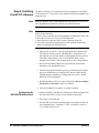
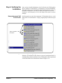
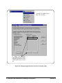
3. From the HP I/O Libraries program group created when the libraries
were installed (Start >> Programs >> HP I_O Libraries), click on
‘I_O Config’ (Figure 2-10).
24
Interface Installation and Configuration
Chapter 2
Figure 2-10. The HP I/O Libraries Program Group.
An alternative is to click on the HP icon in the lower right-hand
corner of your monitor which is placed there following the
installation of the I/O Libraries and configuring the HP E8491B.
Clicking on the HP icon brings up a pop-up menu like that shown in
Figure 2-13. Click on “Run I/O Config”. Either method described in
this step brings up a configuration window similar to Figure 2-11.
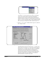
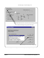
4. Select HP E8491 in the “Available Interface Types” box and click
the ‘Configure’ button.
interface name
interface number
Figure 2-11. The HP I/O Libraries I/O Config Utility.
The HP E8491B uses the SICL interface name ‘vxi’ and the VISA
interface name ‘VXI’ (Figure 2-12). The VISA interface number is
assigned by the ‘I/O Config’ utility and is unique to each E8491B.
The interface name and number identify each mainframe in
multi-frame VXI systems, and are also used in addressing each
instrument in the mainframe. The unique interface number allows
instruments with the same logical addresses to be installed in
different mainframes, but in the same system.
Chapter 2
Interface Installation and Configuration
25
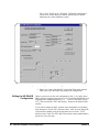
The “Locate” button on the “HP E8491 VXI Board Configuration”
screen can be used to help you identify and keep track of all the
mainframes in a multi-mainframe system.
Figure 2-12. Editing the HP E8491B Configuration.
5. Figure 2-11 returns with the SICL Name and VISA Name inserted.
Click OK to close the utility and complete the configuration.
Editing the HP E8491B
Configuration
When it is necessary to edit your configuration, click ‘I_O Config’ in the
HP I/O Libraries program group (Figure 2-10). To edit the HP E8491B, click
(highlight) the configured interface (“vxi
VXI0”) in the utility (Figure
2-11). This activates the ‘Edit’ and ‘Remove’ buttons at the bottom of the
window.
If you want to change the SICL interface name and number to something
more descriptive, use the ‘SICL Interface Name’ field. You can change the
VISA interface number using the up/down arrows next to the ‘VISA
Interface Name’ field. The SICL and VISA interface names (and numbers)
do not have to be the same.
26
Interface Installation and Configuration
Chapter 2
Make a note of the interface name and number, as they are used in
addressing instruments in the mainframe (see “Chapter 3: VXI
Programming Using the IEEE 1394 Serial Bus” for more information).
The ‘Help’ button provides information on each item in the window.
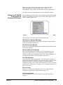
Editing the HP E8491B
Configuration on
Windows 95 Platforms
After installing the HP I/O Libraries and configuring the HP E8491B on the
Windows 95 platform, an hp icon is placed in the bottom right corner of
your PC monitor (Figure 2-13).
Figure 2-13. Editing Your Configuration on Windows 95 Platforms.
Clicking on the icon brings up the following menu items:
Hide Resource Manager Messages
Enable/disable displaying resource manager messages during mainframe
power-on or during a E8491B reset.
Edit VXI Resource Manager
Allows you to edit the Resource Manager configuration files and/or to run
the Resource Manager.
Refresh VXI Resource Manager
Resets and runs the Resource Manger on all VXI mainframes in your
system. You must “refresh” (re-run) the resource manager each time
changes are made to its configuration. NOTE: The resource manager will
run automatically whenever the mainframe is powered on.
Run VISA Assistant
Activates the HP VISA Assistant utility. This utility displays all devices
connected to the interface and their VISA interface address. It provides other
information on drivers, formatted I/O, memory and other attributes.
Formatted I/O allows you to send a SCPI command to a device to confirm
communication with the device or simply to set a command parameter or to
query a device state.
Run I/O Config
Runs the I/O Config utility and brings up the “I/O Config - Interface
Configuration Application” window shown in figure 2-11.
View Documentation
Selects the Readme.txt, the VISA Help file or the SICL Help file for
viewing.
Chapter 2
Interface Installation and Configuration
27
Run Event Viewer
Brings up the event viewer for viewing the Applications Log for your PC.
VISA Logging
Enables/disables the VISA logging, runs the event viewer or the debug
window.
Hide HP I/O Control
Removes the HP icon in the lower right-hand corner of your Windows
95/NT window task bar. To re-install the icon, go to the START button >>
Programs >> HP I_O Libraries and click on HP I_O Libs Control.
Exit
Terminates the HP I/O Libraries Control.
Note
For HP E8491 Controllers to work, the HP I/O Libraries Control must be
running. Executing “Exit” will disable HP E8491B operation.
About HP I/O Libraries Control
Provides the HP I/O Libraries Control version number.
Step 5: Installing
HP VXIplug&play
Instrument Drivers
There are no SCPI instrument drivers installed in, or downloaded to, the
HP E8491B. While this does not impact message-based instruments,
register-based instruments in IEEE 1394 based systems are usually
programmed using their VXIplug&play drivers.
The HP VXIplug&play drivers are located on the HP Universal Instrument
Drivers CD which ships with the E8491B and with each VXI instrument.The
installer program on the driver CD is similar to that on the I/O libraries CD.
Once the drivers have been installed, reboot the PC.
Note
28
If you are updating an existing VXI system to use the HP E8491B and
IEEE 1394 serial bus, we highly recommend that you obtain the latest
version of the HP VXIplug&play drivers. Information on the latest drivers
available can be found on the World Wide Web at
http://www.hp.com/go/inst_drivers .
Interface Installation and Configuration
Chapter 2
Step 6. Verifying the
Installation
Once you have installed the hardware, the I/O Libraries, the VXIplug&play
drivers, and have re-booted the PC, you should now verify the installation.
This ensures that you can communicate with instruments in the system over
the IEEE 1394 interface. Two ways to check your system are to run an
instrument’s soft front panel, or to view the output of the system’s resource
manager.
Using Instrument Soft
Front Panels
Soft front panels are part of the instruments’ VXIplug&play drivers. A soft
front panel is activated from the ‘Vxipnp’ program group as shown in Figure
2-14.
Click to activate a soft
front panel
Figure 2-14. Selecting a VXIplug&play Soft Front Panel.
When the system hardware and software are properly installed and the PC is
communicating with the mainframe, the soft front panel will be opened and
a connection made to the instrument as shown in Figure 2-15.
Chapter 2
Interface Installation and Configuration
29
Green ‘Active’ indicator
shows communication to
instrument
Correct interface name and
logical address shown.
Figure 2-15. Soft Front Panel Indicating PC - Mainframe Communication.
Viewing the Resource
Manager Output
Another way to determine if your system is properly configured is to view
the output of the resource manager. The easiest way to view the output is
using the I/O Libraries’ ‘I/O Config’ utility.
1. Press the HP I/O Libraries Control icon in the lower right-hand side
of your monitor and select “Edit VXI Resource Manager”. In the
Resource Manager pop-up window, select “RM Output”. The
resource manager output will show the “VXI Current Configuration”
with all devices it can communicate with listed in the “VXI Device
Table”.
2. Click on Start >> Programs >> I_O Config to bring up the I/O Config
window (Figure 2-11).
2a. Select the “Configured Interfaces” name corresponding to the
E8491B to bing up the HP E8491 VXI Board Configuration
window (Figure 2-12).
30
Interface Installation and Configuration
Chapter 2
2b. Perform steps 1, 2 and 3 in Figure 2-16.
1. Select Enable Advanced to activate the Advanced Settings controls.
2. Click Resource Manager to bring up the window below.
3. Click RM Output to view the resource manager output.
Figure 2-16. Viewing the Resource Manager Output using ‘I/O Config’.
Chapter 2
Interface Installation and Configuration
31
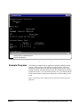
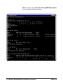
Figure 2-17 is a partial listing of a typical resource manager output.
Figure 2-17. Typical Resource Manager Output (partial listing).
32
Interface Installation and Configuration
Chapter 2
Troubleshooting
Installation
Problems
The following list of troubleshooting items may help you get your HP
E8491B interface working properly if you have encountered problems
verifying installation.
1. It is very important that you upgrade the PC BIOS to the latest version
your PC manufacturer provides whether your PC is new or old. Many early
versions of the PCI BIOS contained bugs. Upgrading to the latest version of
BIOS will eliminate those bugs upgraded by the new BIOS. A BIOS
upgrade and a video driver upgrade may be required to fix PCI-related
problems even on a new PC.
2. Make sure the PCI BIOS is correctly configured. New PC’s have a BIOS
flag that usually reads “Plug&Play OS” or “Running Windows 95”. This
must be set appropriately for the OS you are using; Win 95 is a plug&play
OS whereas, Win NT is not.
3. The HP E8491B requires installation of the PCI-to-IEEE 1394 host
adapter card in a bus-mastering PCI slot. Consult your PC’s user manual to
determine which slots are bus-mastering (it is possible that all slots are
bus-mastering).
4. In addition to the above, you may need to move the HP E8491B to a
separate IRQ line in the PC. PCI allows up to four devices sharing an IRQ
line. However, due to bugs in some cards, this doesn’t always work and you
may need to have one IRQ per card. Moving the IRQ is not easy and whether
it can be done will depend on which operating system you are using and on
the details of the BIOS implementation of your PC.
Running the
Resource Manager
The I/O Libraries Control utility must be running to enable the resource
manager to run. The resource manager initializes and prepares the VXI
system for use. The I/O Libraries Control utility is installed when the
E8491B interface is configured using ‘I/O Config’. It can be accessed by
clicking on the HP logo in the lower right hand corner of your Windows
panel. The resource manager will run when:
• mainframe power is applied or cycled
• the E8491B faceplate “Reset” button is pressed
• activated from the ‘I/O Config’ utility
• activated from the ‘I/O Control’ icon (see Figure 2-13)
In VXI systems with multiple E8491Bs (mainframes), individual
mainframes can be turned off without affecting other mainframes in the
system. When a mainframe is turned on, the resource manager reconfigures
the mainframe.
Note
Chapter 2
The resource manager will only run if the I/O Libraries Control utility is
started.
Interface Installation and Configuration
33
34
Interface Installation and Configuration
Chapter 2
Chapter 3
VXI Programming Using the IEEE 1394
Serial Bus
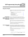
Using this Chapter
This chapter contains examples and general information for programming
VXI systems over the IEEE 1394 serial bus. The contents of the chapter
include:
• Programming Register-Based and Message-Based
Instruments . . . . . . . . . . . . . . . . . . . . . . . . . . . . . . . . . . . . . . 35
35
36
43
47
• Opening Instrument Sessions . . . . . . . . . . . . . . . . . . . . . . . .
• Optimizing Programs . . . . . . . . . . . . . . . . . . . . . . . . . . . . . .
• HP E8491B Triggering . . . . . . . . . . . . . . . . . . . . . . . . . . . . .
• Using HP E8491B Shared Memory . . . . . . . . . . . . . . . . . . .
Programming
Register-Based and
Message-Based VXI
Instruments
There are no SCPI instrument drivers for register-based instruments
installed in, or downloaded to, the HP E8491B. Therefore, register-based
instruments are programmed over the IEEE 1394 bus using either their
VXIplug&play drivers, or through register-level peeks and pokes using
HP VISA or SICL.
Message-based instruments are programmed using HP VXIplug&play
drivers, or using SCPI commands embedded in HP VISA or SICL function
calls.
VXIplug&play drivers for HP register-based and message-based
instruments are contained on the HP Universal Instrument Drivers CD
which ships with each HP VXI instrument.
Opening Instrument
Sessions
Programs which run over the IEEE 1394 interface begin by opening a
session between the VXI instrument and the driver or I/O library (VISA or
SICL). An address that includes the interface name and number (described
in Chapter 2) and the instrument’s logical address is used in opening these
sessions.
Following are three segments that open sessions to an E1563A Digitizer in
HP VXIplug&play, HP VISA, and SICL programs.
HP VXIplug&play
ViSession vi;
// open device (VXIplug&play) session to the HP E1563
errStatus = hpe1563_init(“VXI0::24::INSTR”,VI_FALSE,
VI_FALSE, &vi);
Chapter 3
VXI Programming Using the IEEE 1394 Serial Bus
35
HP VISA
ViSession defaultRM, id;
//open device (VISA) session to the HP E1563
viOpenDefaultRM (&defaultRM);
viOpen (defaultRM, “VXI0::24::INSTR”,VI_NULL,VI_NULL,
&id);
SICL
INST id;
// open device (SICL) session to the HP E1563
id = iopen(“vxi,24”)
Or, to open an interface session to the HP E8491B:
INST id;
// open (SICL) session to the VXI interface
id = iopen(“vxi”)
The HP E8491B IEEE 1394 interconnect uses the VISA interface name
VXI<n> or SICL interface name vxi. The interface number is assigned using
the ‘I/O Config’ utility (see Chapter 2). In the examples above, the logical
address of the HP E1563 digitizer is 24 and INSTR indicates a VISA
instrument control resource.
Optimizing
Programs
Programs that run over the IEEE 1394 serial bus are optimized by
transferring data between the PC and the instrument in blocks. The
following section identifies HP VISA and SICL functions that perform
block transfers.
Note
Refer to “Chapter 4: IEEE 1394 Fundamentals and Interface Overview” for
detailed information on data transfers using the IEEE 1394 data transfer
protocol.
Block Data Transfers
VXIplug&play drivers for selected instruments contain functions that
perform block transfers. You will need to consult the driver help file to
determine if the driver for a particular instrument supports block transfers.
The following HP VISA functions perform block transfers over the
IEEE 1394 serial bus:
viMoveIn8
viMoveIn16
viMoveIn32
36
VXI Programming Using the IEEE 1394 Serial Bus
viMoveOut8
viMoveOut16
viMoveOut32
viMove
viMoveAsync
Chapter 3
The following extended SICL function is unique to the HP E8491B (must be
used on the E8491B) and is used for block transfers over the bus:
iblockmovex
Additionally, the extended SICL functions shown below must be used when
porting SICL programs to the IEEE 1394 bus from other I/O interfaces:
imapx
iunmapx
ipeekx8, ipeekx16, ipeekx32
ipokex8, ipokex16, ipokex32
These functions are covered in detail in the SICL documentation.
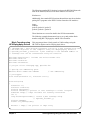
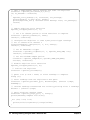
The following examples demonstrate how to set up and perform block
transfers using HP VXIplug&play and HP VISA functions.
Block Transfers using
HP VXIplug&play Drivers
//
//
//
//
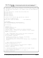
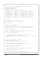
This program performs a block transfer of 2,000 readings using the
HP E1563A digitizer and its VXIplug&play driver.
1563VPNP.CPP - This program transfers a block of 2,000 readings from the
HP E1563 digitizer to the computer using the VXIplug&play driver’s
hpe1563_fetchAll_Q function. 2,000 readings is the maximum number of
readings that can be transferred using the function.
#include
#include
#include
#include
"hpe1563.h"// include the driver header file
<stdio.h>
<stdlib.h>
<windows.h>
// project files: 1563vpnp.cpp, hpe1563.lib
// Specify the addressing path.
#define E1563 "VXI0::64::INSTR"
// VXI addressing
// prototypes
void check(ViSession vi, ViStatus error);
void main(void)
{
ViSession vi;
ViStatus errStatus;
ViInt16 rdgs[2000];
ViInt16 *dataPtr;// pointer to cast readings to 16-bit integers
ViReal64 range;// range variable for reading conversions
int i;
long dataArrayLen=2000;// return 2,000 readings using
// hpe1563_fetchAll_Q
ViInt32 numRdgs;
ViChar err_message[256];
dataPtr = rdgs;// set pointer to rdgs array
Chapter 3
VXI Programming Using the IEEE 1394 Serial Bus
37
// open a VXIplug&play device session and reset the digitizer
errStatus = hpe1563_init(E1563,0,1,&vi);
if( VI_SUCCESS > errStatus)
{
hpe1563_error_message( vi, errStatus, err_message);
printf("Unable to open %s\n", E1563);
printf("hpe1563_init() returned error message %s\n", err_message);
return;
}
// enable digitizer error detection
hpe1563_errorQueryDetect(vi, 1);
// set a 5s timeout period to allow functions to complete
errStatus = hpe1563_timeOut(vi, 5000);
check(vi, errStatus);
// configure the digitizer to take 2,000 post-trigger readings
// not to exceed 4V on channel 1
errStatus=hpe1563_configure(vi, 1, 4.0, 2000,1);
check(vi, errStatus);
// set an immediate trigger
errStatus = hpe1563_trigEvent(vi, 1, hpe1563_TRIG_IMM, 0.0);
check(vi, errStatus);
// set the minimum sample period
errStatus = hpe1563_sampTim(vi, hpe1563_SAMP_TIM_MIN);
check(vi, errStatus);
// disable digitizer error detection
hpe1563_errorQueryDetect(vi, 0);
// initiate the digitizer
errStatus = hpe1563_initImm(vi);
// pause 3 ms (1.3e-6 * 2000) to allow readings to complete
Sleep (3);
// fetch readings from the digitizer’s A24 space
errStatus = hpe1563_fetchAll_Q(vi, dataArrayLen, (ViInt32 *)rdgs,
&numRdgs );
// confirm readings transferred are valid by printing first 5 readings
dataPtr = (ViInt16 *)rdgs;
// query digitizer reading range
errStatus = hpe1563_range_Q(vi, 1, &range);
printf("Reading samples are:\n\n");
for (i=0; i<10; i+=2)
{
printf("%lf\n\n",dataPtr[i]*range/32768);
}
38
VXI Programming Using the IEEE 1394 Serial Bus
Chapter 3
// reset digitizer following the transfer
errStatus = hpe1563_reset(vi);
// close the device session
hpe1563_close(vi);// HP VXIplug&play session
}
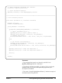
//***********************************************************************
// error checking routine
void check (ViSession vi, ViStatus errStatus)
{
ViInt32 inst_err;
ViChar err_message[256];
if(VI_SUCCESS > errStatus)
{
if(hpe1563_INSTR_ERROR_DETECTED == errStatus)
{
/* query instrument error */
hpe1563_dcl(vi);/* send a device clear */
hpe1563_error_query(vi, &inst_err, err_message);
/* display the error */
printf("Instrument Error : %ld, %s\n", inst_err, err_message);
}
else
{
/* get driver error message */
hpe1563_error_message(vi, errStatus, err_message);
/* display the error */
printf("HP E1563 Driver Error : %ld, %s\n", errStatus, err_message);
}
hpe1563_reset(vi);/* reset the digitizer */
hpe1563_close(vi);/* close the digitizer handle */
exit(1);
}
return;
}
Comments
1. The maximum block transfer size allowed by the HP E1563A
hpe1563_fetchAll_Q function is 2,000 bytes.
2. This manual is included on the HP I_O Libraries CD. By viewing the
manual from the CD, you can cut and paste this program into your
development environment.
3. The section “Using HP E8491B Shared Memory” contains an example of
block data transfers using HP SICL.
Chapter 3
VXI Programming Using the IEEE 1394 Serial Bus
39
Block Transfers using
HP VISA
//
//
//
//
This program performs a block transfer of 60,000 readings using the
HP E1563A digitizer and the HP VISA function viMoveIn32.
1563visa.CPP - This program configures the HP E1563A digitizer using its
VXIplug&play driver and then transfers a block of 60,000 readings from
the digitizer’s FIFO memory to the computer using the VISA viMoveIn32
function.
#include
#include
#include
#include
#include
"hpe1563.h"// include the driver header file
"visa.h"
<stdio.h>
<stdlib.h>
<windows.h>
// project files: 1563visa.cpp, hpe1563.lib, VISA.lib
// specify the addressing path
#define E1563 "VXI0::64::INSTR"
// VXI addressing
// prototypes
void check(ViSession vi, ViStatus error);
void err_handler(ViSession vi, ViStatus err);
void main(void)
{
ViSession vi;
ViStatus errStatus, err;
ViInt32 rdgs[60000];
ViReal64 range;// range variable for reading conversions
ViInt16 *dataPtr;// pointer to cast readings to 16-bit integers
int i;
ViChar err_message[256];
// open a VXIplug&play device session and reset the digitizer
errStatus = hpe1563_init(E1563,0,1,&vi);
if( VI_SUCCESS > errStatus)
{
hpe1563_error_message( vi, errStatus, err_message);
printf("Unable to open %s\n", E1563);
printf("hpe1563_init() returned error message %s\n", err_message);
return;
}
// enable digitizer error detection
hpe1563_errorQueryDetect(vi, 1);
// set a 5s timeout period to allow functions to complete
errStatus = hpe1563_timeOut(vi, 5000);
check(vi, errStatus);
// configure the digitizer to take 60,000 post-trigger readings
// not to exceed 4V on channel 1
errStatus=hpe1563_configure(vi, 1, 4.0, 60000, 1);
check(vi, errStatus);
40
VXI Programming Using the IEEE 1394 Serial Bus
Chapter 3
// set an immediate trigger
errStatus = hpe1563_trigEvent(vi, 1, hpe1563_TRIG_IMM, 0.0);
check(vi, errStatus);
// set the minimum sample period
errStatus = hpe1563_sampTim(vi, hpe1563_SAMP_TIM_MIN);
check(vi, errStatus);
// disable digitizer error detection
hpe1563_errorQueryDetect(vi, 0);
// initiate the digitizer
errStatus = hpe1563_initImm(vi);
// pause 78 ms (1.3e-6 * 60000) to allow readings to complete
Sleep (78);
// transfer the (60,000) readings from the digitizer using the VISA
// function viMoveIn32 - use the same session name (vi) opened for
// VXIplug&play
err = viMoveIn32(vi, VI_A16_SPACE, 0x08, 60000, (ViPUInt32)rdgs);
if(err < VI_SUCCESS) err_handler(vi, err);
// confirm readings transferred are valid
dataPtr = (ViInt16 *)rdgs;
// query digitizer reading range
errStatus = hpe1563_range_Q(vi, 1, &range);
printf("Reading samples are:\n\n");
for (i=0; i<10; i+=2)
{
printf("%lf\n\n",dataPtr[i]*range/32768);
}
// reset digitizer following the transfer
errStatus = hpe1563_reset(vi);
// close the device session
hpe1563_close(vi);// HP VXIplug&play session
}
//************************************************************
// error checking routine
void check (ViSession vi, ViStatus errStatus)
{
ViInt32 inst_err;
ViChar err_message[256];
if(VI_SUCCESS > errStatus)
{
if(hpe1563_INSTR_ERROR_DETECTED == errStatus)
{
Chapter 3
VXI Programming Using the IEEE 1394 Serial Bus
41
/* query instrument error */
hpe1563_dcl(vi);/* send a device clear */
hpe1563_error_query(vi, &inst_err, err_message);
/* display the error */
printf("Instrument Error : %ld, %s\n", inst_err, err_message);
}
else
{
/* get driver error message */
hpe1563_error_message(vi, errStatus, err_message);
/* display the error */
printf("HP E1563 Driver Error : %ld, %s\n", errStatus, err_message);
}
hpe1563_reset(vi);/* reset the digitizer */
hpe1563_close(vi);/* close the digitizer handle */
exit(1);
}
return;
}
//************************************************************************
// Error handling function
void err_handler (ViSession vi, ViStatus err)
{
char buf[1024]={0};
viStatusDesc(vi,err,buf);
printf("ERROR = %s\n", buf);
return;
}
Comments
1. A single instrument session opened with the hpe1563_init function can be
used by both HP VXIplug&play driver function calls and by HP VISA
function (i.e viMoveIn32) calls.
2. This manual is included on the HP I_O Libraries CD. By viewing the
manual from the CD, you can cut and paste this program into your
development environment.
3. The section “Using HP E8491B Shared Memory” contains an example of
block data transfers using HP SICL.
42
VXI Programming Using the IEEE 1394 Serial Bus
Chapter 3
HP E8491B
Triggering
The HP E8491B is capable of asserting, receiving, and routing trigger
signals along the VXI (mainframe) backplane trigger lines. In addition to the
VXI backplane’s eight TTL level trigger lines and two ECL level trigger
lines, the E8491B can receive and assert triggers on the faceplate ‘Trig In’
and ‘Trig Out’ connectors.
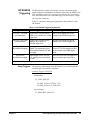
Table 3-1 summarizes the triggering parameters and capabilities of the
HP E8491B.
Table 3-1. HP E8491B Triggering Parameters.
Trigger Lines
Trigger Levels
Trigger Routing
TTLTRG7 - TTLTRG0
(VXI backplane)
Trigger levels or pulses can be
output on any number of TTLTRG
trigger lines.
One TTLTRG trigger line can be
routed to one ECLTRG trigger line.
ECLTRG1 - ECLTRG0
(VXI backplane)
Trigger levels or pulses can be
output on any number of
ECLTRG trigger lines.
One ECLTRG trigger line can be
routed to one TTLTRG trigger line.
Trig In Port*
(HP E8491B faceplate)
Input trigger levels are TTL, ECL,
CMOS, or programmable up to
+30V. Default assumes TTL low
true signal.
Input triggers can be routed to any
number of TTLTRG trigger lines and
to any number of ECLTRG trigger
lines.
Trig Out Port*
(HP E8491B faceplate)
Output trigger level is +5V (low
true - default) and can be pulled
to +30V.
One TTLTRG or ECLTRG trigger line
can be routed to the Trig Out port
* The E8491B Trig In and Trig Out ports are configured using the HP I/O Libraries ‘I/O Config’ utility.
Using Triggers
The triggering functionality of the HP E8491B is accessed through the
following HP VISA and SICL functions:
Asserting Triggers - HP VISA
viSetAttribute
VI_ATTR_TRIG_ID
VI_TRIG_TTL0 to VI_TRIG_TTL7
VI_TRIG_ECL0 to VI_TRIG_ECL1
viAssertTrigger
VI_TRIG_PROT_DEFAULT
Chapter 3
VXI Programming Using the IEEE 1394 Serial Bus
43
Asserting Triggers - HP SICL
ivxitrigoff
ivxitrigon
ixtrig
I_TRIG_ALL
I_TRIG_TTL0 to I_TRIG_TTL7
I_TRIG_ECL0 to I_TRIG_ECL1
I_TRIG_EXT0 (specifies faceplate ‘Trig Out’ port)
Routing Triggers- HP SICL
ivxigettrigroute
ivxitrigroute1
I_TRIG_ALL
I_TRIG_TTL0 to I_TRIG_TTL7
I_TRIG_ECL0 to I_TRIG_ECL1
I_TRIG_EXT0 (specifies faceplate ‘Trig Out’ and ‘Trig In’ ports)
Configuring the E8491B
Trig In and Trig Out Ports
Configuration of the E8491B external ‘Trig In’ and ‘Trig Out’ ports is done
through the HP I/O Libraries’ ‘I/O Config’ utility. This portion of the utility
is shown in the following figure.
Figure 3-1. Configuring the HP E8491B External Trigger Ports.
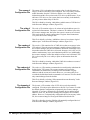
When ‘External Trig In’ is selected, the faceplate ‘Trig In’ port is configured
for the trigger level and state (normally high or normally low) selected.
When ‘External Trig Out’ is selected, the faceplate ‘Trig Out’ port is
configured for the state (normally high or normally low) selected.
1. Trigger routing is only available using the HP SICL ivxitrigroute function.
44
VXI Programming Using the IEEE 1394 Serial Bus
Chapter 3
Note
Triggering Example
//
//
//
//
//
The ‘I/O Config’ help file associated with the HP E8491B interface
contains additional information on configuring the faceplate trigger ports.
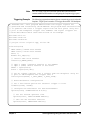
The following program demonstrates how an external trigger received on the
faceplate ‘Trig In’ port is routed to TTL trigger lines on the VXI backplane.
TRIGSICL.CPP - This program demonstrates how trigger signals are
generated and routed using the HP E8491B. The program uses SICL functions
to generate and route a trigger signal from the face plate ‘Trig Out’
port to VXI backplane trigger line TTLTRG4. The signal triggers the
E1412 multimeter which then takes a burst of 10 readings.
#include "sicl.h"
#include <stdio.h>
#include <stdlib.h>
// project files: trigsicl.cpp, sicl32.lib
void main(void)
{
INST e8491;// E8491 SICL handle
INST e1412;// E1412 SICL handle
short i;
double dcv_rdgs[10];
// install SICL error handler
ionerror(I_ERROR_EXIT);
// open
// open
e8491 =
e1412 =
a (SICL) interface session to the E8491B
a (SICL) device session to the E1412
iopen("vxi");
iopen("vxi,24");
// set up trigger routing; rout a trigger from the faceplate 'Trig In'
// port to VXI backplane TTL trigger line 4
ivxitrigroute(e8491, I_TRIG_EXT0, I_TRIG_TTL4);
// E1412 Multimeter configuration
// set a 50s timeout period for external trigger to occur
itimeout(e1412, 50000);
// configure the multimeter for DCV measurements
iprintf(e1412, "CONF:VOLT:DC 8.0\n");
// set the fastest aperture time
iprintf(e1412, "VOLT:DC:APER MIN\n");
// turn off the autozero function
iprintf(e1412, "ZERO:AUTO OFF\n");
Chapter 3
VXI Programming Using the IEEE 1394 Serial Bus
45
// set the trigger source
iprintf(e1412, "TRIG:SOUR TTLT4\n");//trigger line 4
// set the sample count
iprintf(e1412, "SAMP:COUN 10\n");// 10 readings
// initiate the multimeter
iprintf(e1412, "INIT\n");
printf("Press ’Enter’ to trigger the voltmeter\n");
getchar ();
// output a trigger pulse on the E8491B ’Trig Out’ connector, the
// trigger is then input to the ’Trig In’ connector via a jumper wire
// and routed to TTL trigger line 4 which triggers the multimeter
ixtrig(e8491, I_TRIG_EXT0);
// fetch the readings once the trigger is received
ipromptf(e1412, "FETC?\n", "%,10lf", dcv_rdgs);
// display the readings
for (i=0; i<10; i++)
{
printf("%lf\n", dcv_rdgs[i]);
}
// close the device sessions
iclose(e8491);// close SICL interface session
iclose(e1412);// close SICL device session
}
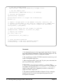
Comments
1. For demonstation purposes, the trigger signal output from the ‘Trig Out’
port (ixtrig function) is routed to the ‘Trig In’ port using a jumper wire. The
signal is then routed to TTLTRG4 (ivxitrigroute function).
2. The external trigger routed to TTLTRG4 can also be routed to any or all
of the VXI backplane trigger lines.
3. When using the faceplate ‘Trig In’ and ‘Trig Out’ ports, notice that both
ports are specified using I_TRIG_EXT0.
In the program, ivxitrigroute(e8491s, I_TRIG_EXT0,
I_TRIG_TTL4)routes the trigger received on the faceplate ‘Trig In’ port
to backplane TTL trigger line 4. ixtrig(e8491s, I_TRIG_EXT0)
outputs a trigger pulse on the ‘Trig Out’ port which is connected by a
jumper wire to the ‘Trig In’ port.
4. This manual is included on the HP I/O Libraries CD. By viewing the
manual from the CD, you can cut and paste this program into your
development environment.
46
VXI Programming Using the IEEE 1394 Serial Bus
Chapter 3
Trigger Pull Up
Trigger signals output from the E8491B ‘Trig Out’ port can be “pulled up”
to +30V as shown in Figure 3-2.
+ V = Pull Up Voltag e (+ 30V M ax)
+V
E8491B
" TRIG OUT "
SM B Connec tor
R
DUT
Outp ut Trig g er State LH = N orm ally Low , Hig h True
Outp ut Trig g er State HL = N orm ally Hig h, Low True (Default)
Figure 3-2. Using a Pull Up on the HP E8491B ‘Trig Out’ Port.
Using HP E8491B
Shared Memory
The E8491B has 128 kBytes of shared (VME) memory. This memory is in
the E8491B’s A24 address space and is available to those VXI instruments
capable of mapping and accessing A24 memory. Shared memory is often
used as a temporary storage space for data transfers between the PC and VXI
instruments.
HP instruments with the ability to store and receive data from shared
memory generally implement the SCPI (Standard Commands for
Programmable Instruments) MEMory:VME subsystem shown below:
MEMory:VME:SIZE
MEMory:VME:ADDRess
MEMory:VME:STATe
Corresponding HP VXIplug&play functions are:
hpexxxx_memVmeAddr
hpexxxx_memVmeSize
hpexxxx_memVmeStat
where xxxx is the instrument model number.
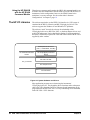
Locating E8491B Shared
Memory
Chapter 3
In order to use the E8491B shared memory, you must first locate the starting
address of the memory as mapped by the resource manager (see “Running
the Resource Manager” in Chapter 2). The address varies from system to
system depending on the number of devices that use A24 memory. The
address can be determined programatically using HP VISA or SICL, or by
viewing the resource manager output. Each method is described in the
following sections.
VXI Programming Using the IEEE 1394 Serial Bus
47
Locating Shared Memory Using HP VISA
For HP VISA programs, the E8491B shared memory starting address is
obtained using the function:
viGetAttribute
and the VXI interface attribute:
VI_ATTR_MEM_BASE
The HP VISA version of the example “Storing Readings in Shared
Memory” demonstrates the use of this function and attribute.
Locating Shared Memory Using SICL
For SICL programs, the E8491B shared memory starting address is found
using the function:
ivxirminfo
This function fills the structure struct vxiinfo. The item within the structure
containing the starting address is memstart. The SICL version of the
example program showing the use of shared memory demonstrates the use
of this function and structure.
Locating Shared Memory by Viewing the Resource Manager
Output
The third method of determining the E8491B’s shared memory starting
address is to view the resource manager output. “Viewing the Resource
Manager Output” in Chapter 2 describes how this is done using the ‘I/O
Config’ utility. Figure 3-3 shows the section of the output that indicates A24
address mapping.
Another way to view the output is using the SICL ivxisc utility contained in
the <drive:>\siclnt\bin or sicl95\bin directory. This utility is an executable
that is used with the SICL logical unit number (see “Editing the HP E8491B
Configuration” in Chapter 2) to return the configuration output of the
resource manager. Again, Figure 3-3 shows a partial listing of the output.
Note
48
Refer to Appendix B for additional information on using ivxisc and for an
example of the complete configuration output.
VXI Programming Using the IEEE 1394 Serial Bus
Chapter 3
starting
address of E8491B shared
memory (hexadecimal)
Figure 3-3. Partial Listing of Resource Manager Output Showing Shared Memory Mapping.
Example Programs
The following examples show an application using the E8491B’s shared
memory. In the program, 8,000 readings are taken with the HP E1410
multimeter. Because the E1410 has only enough memory to store 4,096
readings internally, all 8,000 readings are stored in shared memory and then
transferred to the PC. Given the shared memory size of 128 kBytes and the
E1410 storage format of eight bytes/reading, up to 16,000 readings can be
stored.
Figure 3-4 illustrates the reading transfers performed with the following
programs.
Chapter 3
VXI Programming Using the IEEE 1394 Serial Bus
49
Readings are taken and transferred from the
instrument to E8491B shared memory over
the VXI backplane.
DUT
Readings are transferred in blocks
from shared memory to the PC
over the IEEE 1394 serial bus.
Figure 3-4. Storing Readings in Shared Memory.
Storing Readings in
Shared Memory HP VISA Example
//
//
//
//
This example uses the HP E1410 VXIplug&play driver to configure the
multimeter, take the readings, and store them in E8491B shared memory. HP
VISA functions are used to transfer the readings from shared memory to the
PC.
SHAR_VISA.CPP - This program demonstrates how to access the
HP E8491B’s shared memory. The program stores readings taken
by the HP E1410 multimeter in HP E8491B shared memory, and then
transfers those readings from shared memory to the computer.
#include
#include
#include
#include
#include
"hpe1410.h"// include the driver header file
"visa.h"
<stdio.h>
<stdlib.h>
<windows.h>
// project files: SHAR_VISA.cpp, hpe1410.lib, VISA32.lib
// specify the addressing path to the multimeter
#define E1410 "VXI0::24::INSTR"
// E1410 path
#define E8491 "VXI0::0::INSTR"
// E8491 path
// check for instrument errors
#define INSTR_ERROR 0xBFFC0D07
50
VXI Programming Using the IEEE 1394 Serial Bus
Chapter 3
// set up byte swap function for readings transferred from
// E8491B shared memory to the PC
#define SWAP_FLOAT64(rdgs)
\
{ unsigned char src[8];
*((double *)src) = *((double *)rdgs);
((unsigned char *) (rdgs))[0] = ((unsigned char*) (src))[7];
((unsigned char *) (rdgs))[1] = ((unsigned char*) (src))[6];
((unsigned char *) (rdgs))[2] = ((unsigned char*) (src))[5];
((unsigned char *) (rdgs))[3] = ((unsigned char*) (src))[4];
((unsigned char *) (rdgs))[4] = ((unsigned char*) (src))[3];
((unsigned char *) (rdgs))[5] = ((unsigned char*) (src))[2];
((unsigned char *) (rdgs))[6] = ((unsigned char*) (src))[1];
((unsigned char *) (rdgs))[7] = ((unsigned char*) (src))[0];
}
\
\
\
\
\
\
\
\
\
\
// prototypes
void check(ViSession vi, ViStatus error);
void err_handler(ViSession vi, ViStatus err);
void main(void)
{
ViSession vi, defaultRM, fw;
ViStatus errStatus, err;
unsigned long start_addr;// starting address of shared memory
ViReal64 rdgs[8000];// array for readings from shared memory
int i;
ViChar err_message[256];
// open a VXIplug&play device session and reset the multimeter
errStatus = hpe1410_init(E1410,0,1,&vi);
if( VI_SUCCESS > errStatus)
{
hpe1410_error_message( vi, errStatus, err_message);
printf("Unable to open %s\n", E1410);
printf("hpe1410_init() returned error message %s\n", err_message);
return;
}
// open a VISA session to the E8491B
viOpenDefaultRM(&defaultRM);
viOpen(defaultRM,E8491, VI_NULL, VI_NULL, &fw);
// get E8491B shared memory base address
viGetAttribute(fw, VI_ATTR_MEM_BASE, &start_addr);
// enable multimeter error detection
hpe1410_errorQueryDetect(vi, 1);
// set a 5s timeout period to allow functions to complete
errStatus = hpe1410_timeOut(vi, 5000);
check(vi, errStatus);
// configure the multimeter for DCV measurements
Chapter 3
VXI Programming Using the IEEE 1394 Serial Bus
51
errStatus = hpe1410_confVoltDc(vi);
check(vi, errStatus);
// turn off autorange, set a 30V DCV range
errStatus = hpe1410_voltDcRang(vi, 0, 30);
check(vi, errStatus);
// set a 10 us aperture time
errStatus = hpe1410_voltDcAper(vi, 10.0e-6);
check(vi, errStatus);
// set 8000 readings
errStatus = hpe1410_sampCoun(vi, 8000);
check(vi, errStatus);
// store the readings in HP E8491B shared memory
// specify the E8491B shared memory base address
errStatus = hpe1410_memVmeAddr(vi, start_addr);
check(vi, errStatus);
// specify the amount of memory required
// (8000 readings * 8 bytes/reading)
errStatus = hpe1410_memVmeSize(vi, 64000);
check(vi, errStatus);
// enable the readings to be stored
errStatus = hpe1410_memVmeStat(vi, 1);
// disable multimeter error detection
hpe1410_errorQueryDetect(vi, 0);
// initiate the multimeter to take the readings
errStatus = hpe1410_initImm(vi);
// pause 30s to allow readings to complete
Sleep (30000);
// transfer the 8,000 readings (64,000 bytes) from the multimeter using
// the VISA function viMoveIn8
err = viMoveIn8(fw, VI_A24_SPACE, 0, 64000, (ViPUInt8)rdgs);
if(err < VI_SUCCESS) err_handler(fw, err);
// swap the bytes once they are transferred from shared memory
for (i=0;i<7999;i++)
{
SWAP_FLOAT64(&rdgs[i]);
}
// print some readings to verify the transfer was successful
for (i=0; i<10; i++)
{
printf("%lf\n", rdgs[i]);
}
52
VXI Programming Using the IEEE 1394 Serial Bus
Chapter 3
// close the device sessions
hpe1410_close(vi);
// close E1410 session
viClose(fw);
// close E8491 session
}
//**********************************************************
// error checking routine
void check (ViSession vi, ViStatus errStatus)
{
ViInt32 inst_err;
ViChar err_message[256];
if(VI_SUCCESS > errStatus)
{
if(INSTR_ERROR == errStatus)
{
// query instrument error
hpe1410_dcl(vi);// send a device clear
hpe1410_error_query(vi, &inst_err, err_message);
// display the error
printf("Instrument Error : %ld, %s\n", inst_err, err_message);
}
else
{
// get driver error message
hpe1410_error_message(vi, errStatus, err_message);
// display the error
printf("HP E1410 Driver Error : %ld, %s\n", errStatus, err_message);
}
hpe1410_reset(vi);// reset the multimeter
hpe1410_close(vi);// close the multimeter handle
exit(1);
}
return;
}
//**************************************************************
// Error handling function
void err_handler (ViSession vi, ViStatus err)
{
char buf[1024]={0};
viStatusDesc(vi,err,buf);
printf("ERROR = %s\n", buf);
return;
}
Chapter 3
VXI Programming Using the IEEE 1394 Serial Bus
53
Comments
1. Because of the E1410 multimeter data storage format (eight bytes /
reading), the readings are transferred from shared memory to the PC in
bytes. Therefore, it is necessary to swap each byte in order to re-construct
the reading. Depending on the storage formats of your particular
instruments, swapping may not be necessary.
2. This manual is included on the HP I/O Libraries CD. By viewing the
manual from the CD, you can cut and paste this program into your
development environment.
Storing Readings in
Shared Memory - SICL
Example
//
//
//
//
This example uses the HP E1410 VXIplug&play driver to configure the
multimeter, take the readings, and store them in E8491B shared memory.
SICL functions are used to transfer the readings from shared memory to the
PC.
SHAR_SICL.CPP - This program demonstrates how to access the
HP E8491B’s shared memory. The program stores readings taken by
the HP E1410 multimeter in HP E8491B shared memory, and then
transfers those readings from shared memory to the computer.
#include
#include
#include
#include
"sicl.h"
<stdio.h>
<stdlib.h>
<windows.h>
// project files: SHAR_SICL.cpp, SICL32.lib
// set up byte swap function for readings transferred from
// E8491B shared memory to the PC
#define SWAP_FLOAT64(rdgs) \
{ unsigned char src[8];
*((double *)src) = *((double *)rdgs);
((unsigned char *) (rdgs))[0] = ((unsigned
((unsigned char *) (rdgs))[1] = ((unsigned
((unsigned char *) (rdgs))[2] = ((unsigned
((unsigned char *) (rdgs))[3] = ((unsigned
((unsigned char *) (rdgs))[4] = ((unsigned
((unsigned char *) (rdgs))[5] = ((unsigned
((unsigned char *) (rdgs))[6] = ((unsigned
((unsigned char *) (rdgs))[7] = ((unsigned
}
\
char*)
char*)
char*)
char*)
char*)
char*)
char*)
char*)
\
(src))[7];
(src))[6];
(src))[5];
(src))[4];
(src))[3];
(src))[2];
(src))[1];
(src))[0];
\
\
\
\
\
\
\
\
void main(void)
{
INST e8491;
// handle for SICL session to E8491
INST e1410;
// handle for SICL session to E1410
struct vxiinfo info;
// structure for data returned by ivxirminfo
unsigned long start_addr;
// starting address of shared memory
double rdgs[8000];
// array for readings from shared memory
short i;
unsigned long map;
// memory map space
54
VXI Programming Using the IEEE 1394 Serial Bus
Chapter 3
// install SICL error handler
ionerror(I_ERROR_EXIT);
// open
// open
e8491 =
e1410 =
a (SICL) interface session to the E8491B
a (SICL) device session to the E1410
iopen("vxi");
iopen("vxi,24");
// read the VXI resource manager information in order to determine
// the E8491B shared memory starting address
ivxirminfo(e8491, 0, &info);
start_addr = info.memstart;
// convert address from pages to an address
start_addr = (start_addr*256);
// map E8491B memory space for transfer of readings from
// E8491B shared memory to the computer
map = imapx(e8491, I_MAP_SHARED, 0, 1);
// set a 5s timeout period to allow functions to complete
itimeout(e8491, 5000);
itimeout(e1410, 5000);
// configure the multimeter for DCV measurements
iprintf(e1410, "CONF:VOLT:DC 30.0\n");
// set a 10 us aperture time
iprintf(e1410, "VOLT:APER 10.0e-6\n");
// set 8000 readings
iprintf(e1410, "SAMP:COUN 8000\n");
// store the readings in HP E8491B shared memory
// specify the E8491B shared memory base address
iprintf(e1410, "MEM:VME:ADDR %d\n", start_addr);
// specify the amount of memory required
// (8000 readings * 8 bytes/reading)
iprintf(e1410, "MEM:VME:SIZE 64000\n");
// enable the reading to be stored
iprintf(e1410, "MEM:VME:STAT 1\n");
// initiate the multimeter to take the readings
iprintf(e1410, "INIT\n");
// pause 30s to allow readings to complete and to transfer
// to shared memory
Sleep (30000);
Chapter 3
VXI Programming Using the IEEE 1394 Serial Bus
55
//
//
//
//
transfer the (8000) readings from the multimeter using the SICL
function iblockmovex - the parameters are id, source handle, source
offset, source width, source increment, destination handle, destination
offset, destination width, destination increment, count, and swap
iblockmovex(e8491, map, 0, 8, 1, 0, (unsigned long) rdgs, 8, 1, 64000, 0);
// swap the bytes once they are transferred from shared memory
for (i=0;i<7999;i++)
{
SWAP_FLOAT64(&rdgs[i]);
}
// print some readings to verify the transfer was successful
for (i=0; i<10; i++)
{
printf("%lf\n", rdgs[i]);
}
// unmap memory
iunmapx(e8491, map, I_MAP_SHARED, 0, 1);
// close the device sessions
iclose(e8491);// close SICL interface session
iclose(e1410);// close SICL device session
}
Comments
1. Because of the E1410 multimeter data storage format (eight bytes /
reading), the readings are transferred from shared memory to the PC in
bytes. Therefore, it is necessary to swap each byte in order to re-construct
the reading. Depending on the storage formats of your particular
instruments, swapping may not be necessary.
2. This manual is included on the HP I/O Libraries CD. By viewing the
manual from the CD, you can cut and paste this program into your
development environment.
56
VXI Programming Using the IEEE 1394 Serial Bus
Chapter 3
Chapter 4
IEEE 1394 Fundamentals and
Interface Overview
Using this Chapter
This chapter contains reference information on the IEEE 1394 Serial Bus,
the data transfer protocol, and on the related hardware. The contents of the
chapter include:
• IEEE 1394 Topology and Terminology . . . . . . . . . . . . . . . .
• IEEE 1394 Data Transfer Protocol . . . . . . . . . . . . . . . . . . . .
• The OHCI-Compatible Host Adapter and Interface Cable . .
• The HP E8491B PC to VXI Interconnect . . . . . . . . . . . . . . .
• The HP I/O Libraries. . . . . . . . . . . . . . . . . . . . . . . . . . . . . . .
IEEE 1394 Topology
and Terminology
57
59
61
62
64
Optimizing the IEEE 1394 bus must include an understanding of the
topology and terms associated with its use. Figure 4-1 shows a VXI system
consisting of a PC and three VXI mainframes - interconnected with the IEEE
1394 bus.
PC w/ IEEE 1394-to-PCI
host adapter
VXI mainframe 1
VXI mainframe 3
parent
child
hop
root
node
branch
node
hop
leaf
node
hop
VXI mainframe 2
child
HP E8491A IEEE 1394
to VXI interconnect
leaf
node
Figure 4-1. IEEE 1394 Topology and Terms.
Chapter 4
IEEE 1394 Fundamentals and Interface Overview
57
The terms shown in Figure 4-1 are defined in the following table.
Table 4-1. Definition of Terms.
Host Adapter
Links the computer’s PCI bus to the IEEE 1394 interface. To use a
host adapter, computers must be PCI Rev. 2.0 compliant.
HP E8491B
1394-to-VXI
Interconnect
Links the IEEE 1394 interface to the VXI backplane. Provides the
backplane’s clock and trigger resources.
Root Node
Each device (HP E8491B) on the bus is a “node.” In VXI systems,
the PC is always the root node having cycle master and bus master
capabilities.
Branch Node
A branch node has IEEE 1394 cables connected to two or more
ports. In Figure 1, VXI mainframe 1 is a branch node because of the
1394 cables connecting it to the PC (root node) and to VXI
mainframe 3 on its right.
Leaf Node
A leaf node has a single IEEE 1394 cable connected to it.VXI
mainframes 2 and 3 are leaf nodes.
Parent
A node (HP E8491B) is a parent if it is physically connected closer
to the root than an adjacent node. In Figure 1, VXI mainframe 1 is a
parent node because it is closer to the root than VXI mainframe 3.
Child
A node (HP E8491B) is a child if it is farther from the root than an
adjacent node. In Figure 1, VXI mainframe 3 is a child node
because it is farther from the root than VXI mainframe 1.
A node with a single IEEE 1394 cable connected to it (leaf node) is
always a child (VXI mainframe 2).
Hop
A hop is a IEEE 1394 cable link between nodes. There can be no
more than 16 hops between any two nodes. In the diagram above,
there is a maximum of three hops between nodes. The distance
between any two nodes cannot exceed 72m.
Features of the
IEEE 1394 Bus
The following features of the IEEE 1394 bus apply to all bus applications
including VXI systems.
* Daisy-chain or branching configurations are allowed. There can be no
closed loops (i.e. more than one connection between any two devices).
* Up to 63 devices (including 16 HP E8491Bs) are allowed per bus segment.
One host adapter represents one bus segment.
* There is a maximum of 16 hops between any two devices. The bus cable
length cannot exceed 72 meters between any two devices.
* Live/hot connections. A VXI mainframe anywhere in the configuration
can be turned on/off without affecting the other mainframes. The IEEE 1394
bus automatically reconfigures itself any time a VXI mainframe (or other
device) is added or removed. It is best to do this however, if there are no
data transactions taking place elsewhere in the system.
58
IEEE 1394 Fundamentals and Interface Overview
Chapter 4
Optimizing the
Configuration
I/O performance is impacted slightly by the hardware configuration.The
VXI mainframe closest to the PC (root node) has the highest priority. For
example, if instruments in VXI mainframes 1 and 3 (Figure 4-1) contend for
the bus at the same time, the root node will grant mainframe 1 access to the
bus first. However, the bus’s fair arbitration protocol (covered in the next
section) ensures that each device has equal access to the bus and that devices
closer to the root are not continually granted the bus.
IEEE 1394
Data Transfer
Protocol
Data transfer over the IEEE 1394 bus can be either asynchronous or
isochronous1. Hewlett-Packard’s IEEE 1394 based VXI systems use
asynchronous data transfers and a “fair arbitration” protocol to ensure each
VXI mainframe has equal access to the bus. Figure 4-2 illustrates the
concepts of asynchronous data transfers and fair arbitration.
VXI mainframe 1
VXI mainframe 3
block transfer
block transfer
data packet
data packet
data packet
data packet
VXI mainframe 2
data packet
data packet
Fairness Interval n
F I n-1
mainframe 1 or 2
arb
seq
data
packet
subaction 1
arbitration rest gap
ack
F I n+1
mainframe 1 or 2
arb
seq
data
packet
ack
subaction 2
mainframe 3
arb
seq
data
packet
ack
subaction 3
subaction gaps
arbitration gap
Figure 4-2. IEEE 1394 Data Transfer Protocol.
1. Isochronous data transfers broadcast variable amounts of data at regular intervals with no acknowledgement.
Isochronous and Asynchronous data transfers can occur on the same bus.
Chapter 4
IEEE 1394 Fundamentals and Interface Overview
59
Asynchronous Data
Transfers
During an asynchronous data transfer, a variable amount of data is
transferred to an explicit address in real time, and an acknowledgement is
returned. Data is transferred across the IEEE 1394 bus in packets called
“subactions.” An asynchronous subaction is made up of three parts:
* arbitration sequence - the period when a device requests control of the bus
in order to transmit a data packet.
* data packet - the data packet consists of a data prefix that contains
information about the transaction, the data itself (e.g. VXI instrument
commands), and a data end signal. The maximum packet size is 2 kByte for
400 Mbit adapters such as the adapter supplied with the E8491B.
* acknowledgement - a code returned by the (addressed) data destination
indicating the action taken by the receiver.
The periods between subactions are called subaction gaps. The subaction
gap allows devices that have not had control of the bus during the current
“fairness interval” to arbitrate for control.
Fair Arbitration Protocol
The fair arbitration protocol is based on the fairness interval shown in Figure
2. A fairness interval consists of one or more subactions in which data
packets are transferred over the bus. A fairness interval is as follows:
1. The interval begins when devices (HP E8491B’s) arbitrate for control of
the bus.
2. When a device is granted control, it transfers its data packet and is then
disabled from arbitrating until the next fairness interval.
3. A subaction gap occurs after the previous data packet is transferred.
During this period, remaining devices arbitrate for the bus. The next device
granted the bus transfers its data packet and is then disabled from arbitrating
until the next fairness interval.
4. The fairness interval ends after each device has had an opportunity to
access to the bus and the arbitration reset gap, which is longer than the
subaction gap, occurs. The arbitration reset gap re-enables each device for
arbitration during the next fairness interval.
VXI Data Transfers
60
To take advantage of the IEEE 1394 data transfer protocol, large amounts of
data should be transferred between VXI instruments and the PC using block
transfers. During a block transfer, data is divided into the packets described
previously; the number of packets depends on the amount of data and
whether a 200 Mbit or 400 Mbit host adapter is used. Compared to protocols
that transfer data one byte or one word at a time, transfer speed between the
instrument and the PC is increased because the IEEE 1394 protocol
overhead is associated with the fairness interval and with each packet, rather
than with each byte or word transferred. Thus, transfer speeds (bits/second)
over the IEEE 1394 bus increase as the amount of data transferred (block
size) increases.
IEEE 1394 Fundamentals and Interface Overview
Chapter 4
OHCI-Compatible
Host Adapter and
Interface Cable
The OHCI-compatible PCI-to-IEEE 1394 host adapter is a PC plug-in card1
capable of transferring data at up to 400 MBits/second. The adapter has three
external IEEE 1394 ports. Each OHCI adapter represents one bus segment
capable of supporting up to 63 nodes. If required, the OHCI adapter can
supply 12V with a maximum total current of 0.5A to all three 1394 ports for
IEEE 1394 devices that require power.The layout of a typtical adapter is
shown below.
12 VDC
Power Connector
External
IEEE 1394
Connectors
Figure 4-3. Layout of a Typical OHCI PCI-to-IEEE 1394 Host Adapter.
The interface cable supplied with the host adapter has two power wires and
two signal twisted-pairs. A cross-section of the cable and the cable
connector is shown in Figure 4-4.
1. In the future, IEEE 1394 will be a standard port on selected PCs.
Chapter 4
IEEE 1394 Fundamentals and Interface Overview
61
shields
signal pair wires
6.1 mm
connector
1
3
5
2
4
6
PIN #
COMMENT
1
cable power
2
cable ground
3/4
strobe on receive,
data on transmit
5/6
data on receive,
strobe on transmit
power wires
Figure 4-4. Cross-section of the IEEE 1394 Cable.
The power wires route power from the host adapter to devices (nodes) on the
bus, whether the devices are turned on or off. Since each device in the
system acts as a repeater, the power supplied to a device that is turned off
enables signals to be transferred across that device. This maintains signal
continuity throughout the system.
The HP E8491B PC
to VXI Interconnect
The E8491B is a VXI C-size device (Figure 4-5) normally installed in
mainframe slot 0. With a logical address of 0, the E8491B functions as the
mainframe’s resource manager via software included with the I_O libraries.
The E8491B has 128 kBytes of shared RAM and contains many of the clock
and triggering features found on the HP E1406A Command Module - a VXI
resource manager/slot 0 device common in many GPIB-based systems. A
VXI mainframe with the HP E8491B in slot 0 can also be powered on/off at
any time without affecting other mainframes in the system.
The HP E8491B IEEE 1394 interconnect links the VXI backplane to the
IEEE 1394 bus. However, the E8491B and the IEEE 1394 bus do not extend
the (VXI) backplane between frames in multi-frame VXI systems. This
means that the multimeter and multiplexers in a VXI scanning multimeter
for example, must be installed in the same mainframe. Devices sharing the
VXI Local bus must also be installed in the same mainframe VXI Local bus.
62
IEEE 1394 Fundamentals and Interface Overview
Chapter 4
Annunciators
Failed - a hardware failure
was detected in the HP E8491B,
or the E8491B is performing a
self-test.
IEEE
1394
Failed
VXI
IEEE-1394 - indicates data traffic
over the IEEE 1394 bus
SYSFAIL
IEEE 1394 Ports
SYSFAIL - asserted during a VXI
instrument self-test.
A
IEEE 1394 Ports
VXI - indicates data traffic across
the mainframe’s VXI backplane.
Three ports allow tree topologies
which minimize the number of hops.
Each port is identical and any port or
combination of ports can be used.
B
C
Trigger Ports
Clk In
The E8491B is capable of sourcing
TTL level triggers and receiving
TTL, CMOS, ECL, or user
specified levels up to +30V.
Clk Out
Trig In
Trigger signals can be generated
internally and distributed over the
VXI backplane and to external devices, or the triggers can be distributed from an external source.
Configuration Label
Trig Out
System Clock Ports
The E8491B is capable of sourcing and
receiving the VXI system’s 10 MHz clock.
The system clock (CLK10) is one of the
VXI resources provided by the
mainframe’s slot 0 device. This TTL level
clock is internally generated or can be
received from an external source. The
signal is distributed to every slot in the
mainframe and can also be routed to
external devices.
VXI
Used to identify the interconnect
address in multi-frame VXI
systems.
Reset
HP E8491B
Reset Button
Resets the HP E8491B and all instruments
in the mainframe. Re-runs the resource
manager.
Figure 4-5. The HP E8491B IEEE 1394 to VXI Interconnect.
Chapter 4
IEEE 1394 Fundamentals and Interface Overview
63
Using the HP E8491B
with the HP E1406
Command Module
Though not a common configuration, the HP E1406 command module can
be used in the same mainframe as the HP E8491 to provide HP-IB access to
instruments. In this configuration, however, the E8491B must be the
mainframe’s resource manager. See the section titled “Alternate
Configurations” in Chapter 2, page 19.
The HP I/O Libraries
The software required to use the IEEE 1394 interface in a VXI system is
contained in the HP I/O Libraries and HP VXIplug&play Drivers. The
software supports the Windows 95 and Windows NT platforms.
The software “stack” shown below shows the relationship of the
VXIplug&play drivers to HP VISA/ SICL, to the host adapter drivers, and
to the VXI instruments. Notice that Hewlett-Packard’s implementation of
the IEEE 1394 interface requires HP VISA and will not work with the VISA
supplied by other vendors.
Development Environment
(C/C++, Visual BASIC, HP VEE)
HP Universal Instrument
Drivers
HP VXI plug&play Instrument
Drivers
HP VISA / HP SICL
HP I_O Libraries
Host Adapter Drivers
VXI Instruments
Figure 4-6. System Software and Drivers.
Most application programs are written using the instruments’
VXIplug&play drivers. The plug&play driver functions make subsequent
calls to the VISA functions and so on. Message-based instruments can be
programmed at the HP VISA / SICL level by embedding SCPI commands
in the HP VISA / SICL functions.
64
IEEE 1394 Fundamentals and Interface Overview
Chapter 4
Appendix A
Specifications
The following specifications define the operating and performance
characteristics of the HP E8491B.
Interface
Characteristics
Operating System
Windows 95
Windows NT
Controllers
PC based
I/O Library
SICL / VISA
Backplane
PCI
Interface
IEEE 1394
Maximum I/O Speed*
16-bit: 1.76 MBytes/s to PC
2.50 MBytes/s to HP E8491B
* 200 MHz Pentium PC
/
400 MHz Selectron
Host
32 bit: 1.0 MByte/s to PC
1.0 MByte/s to HP E8491B
Languages
VXI Characteristics
Appendix A
C/C++, Visual Basic, HP VEE, LabView
General
VXI Device Type
Message-based commander
Data transfer bus
n/a
Slot 0 functionality
Yes
Resource Manager Functionality
Yes
MXIbus Resource Manager
Yes
Size
C
Slots
1
Connectors
P1 / P2
Shared Memory
128 kBytes
VXI busses
TTL trigger bus, ECL trigger bus
C-size compatibility
n/a
Specifications
65
CLK 10
Clk In
Input
TTL
Frequency Stability
100 ppm
Duty Cycle
50% ± 5%
Clk Out
Output
TTL
Frequency Stability
100 ppm
Duty Cycle
50% ± 5%
External Trigger Input
Connector
SMB (on faceplate)
Levels
TTL, CMOS, ECL, 0 to +33V
Programmable Threshold
Range
0 to +30V
Programmable Threshold
Accuracy
± 0.4V
Threshold Sensitivity
(hysteresis)
0.5 Vpp maximum
0.1 Vpp minimum
Input Load
50 pf, 55 kohms
Maximum Rate
2 MHz
Minimum Pulse Width
200 ns
External Trigger Output
66
Specifications
Connector
SMB (on faceplate)
Levels
nominal pull up to + 5V
Maximum External Pull Up
+ 30V
Sink Current
10 mA @ Vol < 0.4V or
150 mA @ Vol < 1.0V
Appendix A
Trigger Delays
Maximum delay from TTLTRG to
ECLTRG
60 ns
Maximum delay from ECLTRG to
TTLTRG
60 ns
Maximum delay from Trig In port
to ECLTRG or TTLTRG
300ns
Maximum delay from TTLTRG or
ECLTRG to Trig Out port
100 ns
Cooling
Watts / slot
20W
∆ P mm H20
0.10
Air flow liters / s
2.0
Power Supply Loading
Appendix A
IPM (amps)
IDM (amps)
+5V
2.5
0.001
+12V
0.35
0.050
-12V
0.015
0.001
+24V
0.0
0.0
-24V
0.0
0.0
-5.2V
0.180
0.001
-2V
0.360
0.001
Specifications
67
68
Specifications
Appendix A
Appendix B
Editing the HP E8491B Resource Manager
Configuration
Introduction
The resource manager functionality provided through the HP E8491B
configures your VXI system based on rules specified by the VXI standard.
The configuration can be viewed or modified through the configuration files
and utility functions outlined in this appendix.
Configuration File
Overview
Configuration files (.cf extension) are placed in the <drive:>\siclnt\defaults
or \sicl95\defaults directory when the HP I/O Libraries are installed. Except
where noted, the following files can be edited from the HP I/O Libraries’
‘I/O Config’ utility (Figure B-1) as shown on the following pages. When
editing a file, note the following:
1. Add your entry(ies) below the commented (lines).
2. The first column must contain an entry. Any number of spaces can
separate remaining entries on the line.
Appendix B
Editing the HP E8491B Resource Manager Configuration
69
1. From the I_O Libraries program
group, click I_O Config.
2. Select the configured
HP E8491B interface and then
click Edit. This brings up the
window (partial view) in Figure
B-2.
Figure B-1. Editing Configuration Files from the ‘I/O Config’ Utility.
70
Editing the HP E8491B Resource Manager Configuration
Appendix B
3. Check Enable Advanced and then
click Resource Manager...
4. Select the portion of the configuration
to edit and then click Edit.
Figure B-2. Editing Configuration Files from the ‘I/O Config’ Utility (cont’d).
Appendix B
Editing the HP E8491B Resource Manager Configuration
71
The names.cf
Configuration File
The names.cf file is a database that contains a list of symbolic names to
assign VXI devices that have been configured. The ivxirm utility reads the
model id number from the VXI device and the ivxisc utility uses that
information and this file to print out the VXI device symbolic name. If you
add a new VXI device to your system that is not currently in the database,
you may want to add an entry to this file.
This file is edited by selecting “Add/delete symbolic names of VXI devices”
in the Resource Manager window (Figure B-2).
The oride.cf
Configuration File
The oride.cf file contains values to be written to logical address space for
register-based instruments. This data is written to A16 address space after
the resource manager runs, but before the system’s resources are released.
This can be used for custom configuration of register-based instruments
every time the resource manager runs.
This file is edited by selecting “Add/delete values to be written to logical
address space” in the Resource Manager window (Figure B-2).
The vmedev.cf
Configuration File
The vmedev.cf file contains a list of VME devices that use resources in the
VXI cardcage. Since the resource manager is unable to detect VME devices,
the resource manager uses this information to determine such things as the
slot number where the VME device is located, what type (A16, A24, or A32)
and how much memory it uses, and what interrupt lines it uses. Additionally,
the resource manager verifies that multiple resources aren’t allocated. This
file is also used by the ivxisc utility to print out information about the
devices.
This file is edited by selecting “Add/delete VME devices that use resources”
in the Resource Manager window (Figure B-2).
The cmdrsrvt.cf
Configuration File
The cmdrsrvt.cf file contains a commander/servant hierarchy other than the
default for the VXI system. The resource manager will set up the
commander/servant hierarchy according to the commander’s logical
addresses and the servant area switch. However, you can use this file to
override the default based on the commander’s servant area. This file should
only contain changes from the default.
This file is edited by selecting “Edit commander/servant hierarchy” in the
Resource Manager window (Figure B-2).
The dynamic.cf
Configuration File
The dynamic.cf file contains a list of VXI devices to be dynamically
configured. You only need to add entries to this file if you want to override
the default dynamic configuration assignment by the resource manager.
Normally, if you have a dynamically configurable device and the logical
address is set at 255, the resource manager will assign the first available
address. However, if a dynamically configurable device has an entry in this
file, the resource manager will assign the address listed in the file.
This file is edited by selecting “Edit list of dynamically configured devices”
in the Resource Manager window (Figure B-2).
72
Editing the HP E8491B Resource Manager Configuration
Appendix B
The irq.cf Configuration
File
The irq.cf file is a database that maps specific interrupt lines to VXI interrupt
handlers. If you have non-programmable interrupters and you want the
interrupters to be recognized by a VXI interrupt handler, you must make an
entry in this file. Additionally, if you have progammable interrupters and
you want them to be recognized by a device other than what’s assigned by
the resource manager (the commander of that device), you can make an
entry in this file to override the default. Keep in mind that not all VXI
devices need to use interrupt lines and not all interrupt lines need to be
assigned. Note that any interrupt lines assigned in this file cannot also be
assigned in the vmedev.cf configurtion file.
This file is edited by selecting “Edit mapping of VXI devices to interrupt
lines” in the Resource Manager window (Figure B-2).
The ttltrig.cf
Configuration File
The ttltrig.cf file contains the mapping of VXI devices to TTL trigger lines
in extended VXI systems. If you have a MXI-extended
(multiple-mainframe) system and you are sending / receiving triggers
between mainframes, you must map the TTL trigger line to the logical
address of the device asserting the trigger. This file is only used for extended
VXI systems.
This file is edited by selecting “Edit mapping of VXI devices to ttl trigger
lines” in the Resource Manager window (Figure B-2).
The vximanuf.cf
Configuration File
The vximanuf.cf file contains a database that cross references the VXI
manufacturer id numbers and the name of the manufacturer. The ivxirm
utility reads the manufacturer id number from the VXI device. The ivxisc
utility then uses that number and this file to print out the name of the
manufacturer. If you add a new VXI device from a vendor that is not
currently in the file, you may want to add an entry to the file.
This file can not be edited using ‘I/O Config’.
The vximodel.cf
Configuration File
The vximodel.cf file contains a database that lists a cross reference of
manufacturer id, model id, and VXI device names. The ivxirm utility reads
the model id number from the VXI device and the ivxisc utility uses that
information and this file to print out the VXI device model. If you add a new
VXI device to your system that is not currently in this database, you may
want to add an entry to this file.
This file can not be edited using ‘I/O Config’.
Utility Function
Overview
Within the <drive:>\siclnt\bin or \sicl95\bin directory are utility functions
that view the resource manager output (ivxisc) and which clear the
HP E8491B interface (iclear) and run the resource manager (if the iproc
utility is running).
Using ivxisc
The ivxisc function is used to view the resource manager output. ivxisc is
executed from the Windows command (DOS) prompt (..\siclnt\bin or
\sicl95\bin directory) as:
ivxisc vxi<logical unit>
Appendix B
Editing the HP E8491B Resource Manager Configuration
73
where <logical unit> is the value from the ‘Logical Unit’ window in
the HP I/O Libraries ‘I/O Config’ utility. An example of the output produced
by ivxisc is shown in Figures B-3 and B-4.
Figure B-3. Output of ivxisc.
74
Editing the HP E8491B Resource Manager Configuration
Appendix B
Figure B-4. Output of ivxisc (cont’d).
Using iclear
The iclear function is used to clear the interface (HP E8491B) or individual
message-based instruments in the VXI mainframe. iclear is executed from
the DOS command prompt (..\siclnt\bin or \sicl95\bin directory) as:
iclear <SICL interface name, [logical address]>
SICL interface name is the name (vxi) listed in the ‘I/O Config’ SICL
Interface Name window. logical address is the address of the
message-based VXI instrument to be cleared.
If a logical address is not specified, the (E8491B) interface is cleared and the
resource manager is started.
Appendix B
Editing the HP E8491B Resource Manager Configuration
75
76
Editing the HP E8491B Resource Manager Configuration
Appendix B
Index
HP E8491B IEEE 1394 PC Link to VXI
Configuration and User’s Guide
A
alternate configurations, 19
applying power, 33
asynchronous data transfers, 60
E
E1406
using the E8491B with, 19
E8491B
configuring, 24
B
BIOS, 33
Block, 36–37, 40
block data transfers, 36
using HP VISA, 40
using HP VXIplug&play drivers, 37
bus-mastering PCI slot, 33
C
CLK 10 specifications, 66
cmdrsrvt.cf, 72
configuration file overview, 69
configuration files
cmdrsrvt.cf, 72
dynamic.cf, 72
irq.cf, 73
names.cf, 72
oride.cf, 72
ttltrg.cf, 73
vmedev.cf, 72
vximanuf.cf, 73
vximodel.cf, 73
configuring the E8491B interconnect, 24
configuring the Trig In and Trig Out ports, 44
connecting the HP E8491B to the host adapter, 18
cooling, 67
D
data transfer protocol, 59
asynchronous transfers, 60
fair arbitration, 60
data transfers
over VXI, 60
dynamic.cf, 72
editing the configuration, 26
Windows 95 platforms, 27
examples
HP VISA block data transfers, 40
HP VXIplug&play block data transfers, 37
storing readings in shared memory - HP
VISA, 50
storing readings in shared memory - SICL, 54
triggering, 45
external trigger input
specifications, 66
external trigger output
specifications, 66
F
fair arbitration, 60
first time configuration, 24
H
host adapter and interface cable
overview, 61
HP E1406
using the command module with the HP
E8491B, 64
HP E8491B
connecting the host adapter, 18
installation, 17
overview, 62
triggering, 43
HP I/O Libraries
installation, 24
overview, 64
HP VXIplug&play drivers
installation, 28
Index
77
I
I/O Libraries
installation, 24
iclear, 75
IEEE 1394
bus features, 58
data transfer protocol, 59
topology and terminology, 57
IEEE 1394 host adapter
installation, 13
installation
A/B-size instruments, 22
C-size instruments, 21
host adapter, 13
HP E8491B, 17
HP I/O Libraries, 24
HP VXIplug&play drivers, 28
verifying, 29
VXI instruments, 20
installation problems, troubleshooting, 33
Installing, 21–22
instrument sessions
opening, 35
interface cable and host adapter
overview, 61
interface characteristics
specifications, 65
iproc, 33
IRQ line, 33
irq.cf, 73
ivxisc, 73
L
loading
power supply, 67
locating E8491B shared memory, 47
locating shared memory
using HP SICL, 48
using HP VISA, 48
M
message-based instruments
programming, 35
MXI
using the E8491B with MXI systems, 19
O
opening instrument sessions, 35
HP VISA, 36
HP VXIplug&play, 35
SICL, 36
optimizing programs, 36
oride.cf, 72
P
PCI BIOS, 33
plug&play drivers
installation, 28
porting SICL programs, 36
power supply loading, 67
programming register-based and message-based VXI
instruments, 35
pull up, Trig Out port, 47
R
register-based instruments
programming, 35
resource manager, 33
viewing the output, 30
resource manager configuration
editing, 26
running the resource manager, 33
S
shared memory, 47
locating using HP VISA, 48
locating using SICL, 48
shared memory examples, 49
SICL programs
porting for use with the E8491B, 36
soft front panels
for installation verification, 29
specifications
CLK 10, 66
cooling, 67
external trigger input, 66
external trigger output, 66
general, 65
interface characteristics, 65
power supply loading, 67
trigger delays, 67
storing readings in shared memory
N
names.cf, 72
78
Index
HP VISA example, 50
SICL example, 54
T
Trig In
specifications, 66
Trig In port
configuring, 44
Trig Out port
configuring, 44
specifications, 66
trigger delay
specifications, 67
triggering, 43
example, 45
pull up, 47
troubleshooting installation problems, 33
ttltrg.cf, 73
turning on the mainframe, 33
U
Using, 47
using HP E8491B shared memory, 47
using instrument soft front panels, 29
using the HP E8491B with the HP E1406 Command
Module, 64
utility functions, 73
iclear, 75
ivxisc, 73
V
verifying the installation, 29
viewing the resource manager output, 30
vmedev.cf, 72
VXI characteristics
specifications, 65
VXI data transfers, 60
VXI instruments
installation, 20
installing A/B-size, 22
installing C-size, 21
vximanu.cf, 73
vximodel.cf, 73
VXI-MXI systems
using the E8491B with, 19
VXIplug&play drivers
installation, 28
Index
79
80
Index