1
C-DOT CCS7
USER'S MANUAL
Section No. 407-027-0726
System
Practices
Draft 01, November 1998
C-DOT CCS7
USER'S MANUAL
© 1998, C-DOT
Printed in India
C-DOT CCS7
USER'S MANUAL
DRAFT 01
NOVEMBER 1998
KARTIKA 2055
SERIES 000 : OVERVIEW
CSP SECTION NO. 407-027-0726
THIS C–DOT SYSTEM PRACTICE REFERS TO THE C–DOT SIGNALLING SYSTEM #7
(ABBREVIATED AS C-DOT SS7 IN THE REST OF THIS PUBLICATION).
THE INFORMATION IN THIS SYSTEM PRACTICE IS FOR INFORMATION PURPOSES AND IS
SUBJECT TO CHANGE WITHOUT NOTICE.
A COMMENT FORM HAS BEEN INCLUDED AT THE END OF THIS PUBLICATION FOR
READER'S COMMENTS. IF THE FORM HAS BEEN USED, COMMENTS MAY BE
ADDRESSED TO THE DIRECTOR (SYSTEMS ), CENTRE FOR DEVELOPMENT OF
TELEMATICS, 39, MAIN PUSA ROAD, NEW DELHI - 110 005
© 1998 BY C–DOT, NEW DELHI.
Table of Contents
Chapter 1.
Introduction ..............................................................................................................................5
1.1. Purpose & Scope ................................................................................................................5
1.2. Organisation of Contents ..................................................................................................5
1.3. Overview of Signalling Systems .......................................................................................6
1.4. Advantages of Common Channel Signalling ...................................................................6
1.5. Overview of Signalling System No.7 ..............................................................................10
1.6. Protocol Specifications.....................................................................................................17
Chapter 2.
CCS7 Capability in C-DOT DSS MAX ..................................................................................18
2.1. Overview of C-DOT DSS MAX Architecture..................................................................18
2.2. CCS7 Signalling Unit Module.........................................................................................20
Chapter 3.
SUM Architecture...................................................................................................................23
3.1. System Architecture ........................................................................................................23
3.2. Hardware Architecture ..................................................................................................25
3.3. Software Architecture .....................................................................................................25
Chapter 4.
Call Processing........................................................................................................................31
4.1. Introduction .....................................................................................................................31
4.2. ISUP Call Message Sequence .........................................................................................31
4.3. ISUP Terminating Call ...................................................................................................31
4.4. ISUP Transit Call ............................................................................................................34
Chapter 5.
Command Directory ...............................................................................................................36
5.1. Introduction .....................................................................................................................36
5.2. Commands Directory.......................................................................................................36
5.3. Command Flow ................................................................................................................37
Chapter 6.
Parameters Description..........................................................................................................41
6.1. Introduction .....................................................................................................................41
6.2. Parameters Description...................................................................................................41
Chapter 7.
Operator Command Sheets....................................................................................................56
7.1. Introduction .....................................................................................................................56
7.2. CCS7 Administration Commands: Update Class ..........................................................58
7.3. CCS7 Administration Commands: Display Class..........................................................97
7.4. CCS7 maintenance Commands: Update Class ............................................................111
7.5.CCS7 Maintenance Commands: Display Class ............................................................119
7.6. Existing Commands Modified for CCS7.......................................................................125
Chapter 8.
SUM Packaging & Interconnections ...................................................................................157
8.1. SUM Packaging .............................................................................................................157
8.2. SUM Firmware ..............................................................................................................160
8.3. SUM Interconnections...................................................................................................160
Chapter 9.
SUM Retrofit Procedure.......................................................................................................168
9.1. Introduction ...................................................................................................................168
9.2. SUM Retrofit Procedure................................................................................................168
9.3. Unequipping SUM in a Working Switch......................................................................171
9.4. Utilisation of Unused Time-Slots .................................................................................173
Chapter 10.
SUM Initialization................................................................................................................174
10.1. Overview ......................................................................................................................174
10.2. Levels of Initialization.................................................................................................174
10.3. Conditions of Initialization .........................................................................................176
10.4. Post-Initialization Checks ...........................................................................................177
Chapter 11.
Routine Maintenance ...........................................................................................................178
11.1. General .........................................................................................................................178
11.2. Role of Maintenance Personnel ..................................................................................178
11.3. Routine Maintenance of SUM.....................................................................................181
Chapter 12.
Engineering the SUM...........................................................................................................190
12.1. Engineering Considerations .......................................................................................190
12.2. Signalling Network Connectivity: An Example 1......................................................191
12.3. Signalling Network Connectivity: Example 2............................................................193
Annexure - I
CCS7 Data Creation for PSTN/ISDN Application..............................................................195
Annexure – II
CCS7 Data Creation for SSP Application ...........................................................................200
Annexure - III
CCS7 Related System Parameters ......................................................................................206
H:\HOME\CCIT7\WORD\CSUSRMN1.DOC
11 November, 1998
Chapter 1.
Introduction
1.1.
PURPOSE & SCOPE
The purpose of this document is to provide complete and detailed information on the
implementation of ITU-T (formerly CCITT) Common Channel Signalling System
No.7 (CCS7) in C-DOT DSS MAX switching systems. The architecture of the
signalling unit, its MML interface, and operations and maintenance aspects are
discussed in detail. This document would be useful for anyone interested in
gathering detailed information about C-DOT CCS7 as well as to the exchange O&M
personnel. For technical persons, involved in design or testing and validation of
CCS7, this document will prove to be a good starting point in understanding the
implementation of CCS7 in the switch.
1.2.
ORGANISATION OF CONTENTS
There are twelve chapters in the document including the present one. In the
following sections of this chapter, the advantages of common channel signalling
systems over CAS systems, and the features and capabilities of CCS7 are briefly
described. The international standards and other references followed in the design
of CCS7 are also listed.
Chapter 2 presents a brief on the system architecture of C-DOT DSS MAX and the
place of the CCS7 Signalling Unit Module (SUM) in the overall switch architecture.
The overall architecture of SUM is also described here.
Chapter 3 is on the hardware and software architecture of the SUM and the
packaging of its hardware components.
Chapter 4 deals with CCS7 (ISDN User Part) call processing in C-DOT DSS MAX.
Here, the interaction between the hardware and software while handling different
types of ISUP calls has been described.
In Chapters 5, 6 & 7 the man-machine interface for carrying out operations and
maintenance functions is described.
Chapter 8 covers the SUM packaging and interconnection aspects.
Chapter 9, 10 & 11 are on the retrofit procedure installation and maintenance
procedures.
USER'S MANUAL
5
Chapter 1
Finally, in Chapter 12, engineering of the SUM resources is discussed.
1.3.
OVERVIEW OF SIGNALLING SYSTEMS
One of the major factors influencing the development of signalling systems is the
relationship between signalling and the control function of exchanges. Early
telecommunication networks used analogue step-by-step exchanges. In such
systems, the control and switch functions are co-located, and when a call is made,
the signalling and traffic follow the same path within the exchange. This is known
as Channel Associated Signalling (CAS). In this case, the signalling and traffic also
follow the same path external to the exchange, i.e. on the transmission link.
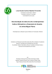
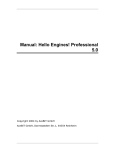
The next stage through which the exchanges evolved is shown in Fig.1.1. In such
exchange the control mechanism for setting-up and releasing calls is separated from
the switch block. The technique allows much more flexibility in controlling calls and
it also reduces costs. Again, CAS systems are typically associated with this type of
exchange. Whereas signalling information is carried on the same path as its
associated speech circuit external to the exchange, the two are separated within the
exchange. This is shown in Fig. 1.1 in which the speech traffic circuits (denoted by
solid lines) are routed by the switch block but the signalling information (denoted
by dotted lines) is routed via the control function. Between Exchanges A and B, the
signalling and traffic are carried over the same path. This approach was primarily
designed to allow optimisation of functions within exchanges, but its effectiveness is
constrained by the need to combine signalling and speech traffic external to the
exchange.
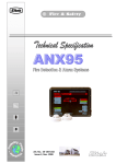
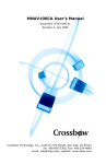
With Common Channel Signalling (CCS) systems, the philosophy is to separate the
signalling path from the speech path. The separation occurs both within the
exchange and external to the exchange (Fig.1.2), thus allowing optimisation of the
control processes, switch block and signalling systems. Fig.1.2 illustrates that, in a
CCS environment, the switch block routs the speech paths as before, however, a
separate path internal to the exchange routs the signalling (denoted by a dotted
line). This approach allows maximum flexibility in optimising exchange and
signalling development. The approach gains maximum benefit when adopted in
parallel with the introduction of digital exchanges and digital transmission
systems. CCS system being particularly efficient in these circumstances.
1.4.
ADVANTAGES OF COMMON CHANNEL SIGNALLING
Common Channel Signalling is being adopted throughout the world in national and
international networks for numerous reasons. The main reasons are:
6
a)
The rapidly changing control techniques of exchanges
b)
The limitations of CAS systems
c)
The evolutionary potential of CCS systems
C-DOT CCS7
INTRODUCTION
EXCHANGE B
EXCHANGE A
SPEECH
X
X
X
X
SIGNALLING
SWITCH BLOCK
CONTROL
SWITCH BLOCK
CONTROL
LEGEND :
SPEECH
SIGNALLING
FIG. 1.1
CAS SIGNALLING WITH SEPARATE CONTROL AND SWITCH BLOCKS
\DESIGN\CCS7-UM\CCS7-CA
USER'S MANUAL
7
Chapter 1
EXCHANGE A
EXCHANGE B
SPEECH
X
X
X
X
X
X
SWITCH BLOCK
SWITCH BLOCK
SIGNALLING
CONTROL
CONTROL
FIG. 1.2
COMMON CHANNEL SIGNALLING
\DESIGN\CCS7-UM\CCS7-CC
8
C-DOT CCS7
INTRODUCTION
One result of the evolutionary process of exchanges described above is to change the
relationship between signalling and call control. In the early exchange systems,
exchanges could communicate, but in a limited and inflexible manner, thus limiting
the flexibility of call control. In a CCS environment, the objective is to allow
uninhibited communication between exchange control functions, or processors, thus
tremendously broadening the scope and flexibility of information transfer.
Further advantages result from the evolutionary process of CCS and call control.
The drive to provide an unrestricted communication capability between exchange
processors eliminates per-circuit signalling termination costs. These costs are
inevitable in per-circuit CAS systems, but for funelling all signalling information
into a single common-channel, only one signalling termination cost is incurred for
each transmission link. There are cost penalties for CCS systems; e.g. the messages
received by an exchange have to be analysed, resulting in a processing overhead.
However, these cost penalties are more than covered by the advantages of increased
scope of inter-processor communication and more efficient processor activity.
The separation of CCS from traffic circuits, and the direct inter-connection of
exchange processors, are the early steps in establishing a cohesive CCS network to
allow unimpeded signalling transfer between customers and nodes and between
nodes in the network. The concept of a cohesive CCS network opens up the
opportunity for the implementation of a wide range of network management,
administrative, operation and maintenance functions. A major example of such a
function is the quasi-associated mode of operation. This mode of operation provides
a great deal of flexibility in network security, reduces the cost of CCS on small
traffic routes and extends the data-transfer capabilities for non-circuit-related
signalling.
CAS systems possess limited information-transfer capability due to:
i)
The restricted number of conditions that can be applied (e.g. the limited
variations that can be applied to a D.C. loop or the limited number of
frequency combinations that can be implemented in a voice frequency
system)
ii)
The limited number of opportunities to transfer signals (e.g. it is not possible
to transmit voice-frequency signals during the conversation phase of a call
without inconveniencing the customers or taking special measures).
Neither of these restrictions applies to CCS. The flexible message-based approach
allows a vast range of information to be defined and the information can be sent
during any stage of a call. Hence, the repertoire of CCS is far greater than channelassociated versions and messages can be transferred at any stage of a call without
affecting the calling and called subscribers.
CCS systems transfer signals very quickly, i.e. at 64 Kbps. This speedy signalling
also permits the inclusion of far more information without an increase in postdialling delay.
USER'S MANUAL
9
Chapter 1
Techniques used in modern CCS system can further improve the flexibility provided
to customers. ‘User-to-user’ signalling and end-to-end signalling techniques are
used whereby messages can be transferred from one customer to another without
undergoing a full analysis at each exchange in the network. Whilst forms of end-toend signalling are possible using CAS systems, the technique can be more
efficiently implemented with CCS systems.
One of the problems that prompted the development of CCS systems was ‘speech
clipping’ in the international network. In some CAS systems, it is necessary to split
the speech path during call set-up to avoid tones being heard by the calling
customer. This results in a slow return of the answer signal and, if the called
customer starts speaking immediately after answer, then the first part of the
statement by the called customer is lost. As the first statement is usually the
identity of the called customer, this causes a great deal of confusion and
inconvenience. CCS systems avoid the problem by transferring the answer signal
quickly.
As a result of the processing ability of CCS systems, a high degree of reliability can
be designed into the signalling network. Error detection and correction techniques
can be applied which ensure reliable transfer of uncorrupted information. In the
case of an intermediate exchange failure, re-routing can take place within the
signalling network, enabling signalling transfer to be continued. While these
features introduce extra requirements, the common channel approach to signalling
allows a high degree of reliability to be implemented economically.
A major restriction of CAS is the lack of flexibility, e.g. the ability to add new
features is limited. One factor that led to the development of CCS was the
increasing need to add new features and respond to new network requirements.
Responses to new requirements in CCS can be far more rapid and comprehensive
than for channel associated versions.
CCS systems are not just designed to meet current needs. They are designed to be
as flexible as possible in meeting future requirements. One way of achieving the
objective is to define modern CCS systems in a structured way, specifying the
signalling system in a number of tiers. The result is flexible signalling system that
reacts quickly to evolving requirements and future services can be incorporated in a
flexible and comprehensive manner. Changes to existing services can be
implemented more quickly and at lower cost than with CAS systems.
1.5.
OVERVIEW OF SIGNALLING SYSTEM NO.7
Signalling System No.7 (CCS7) is a message based signalling system between
Stored Program Controlled (SPC) switches. Where the intermediate nodes may be
used as Signal Transfer Points (STPs), CCS7 network can be used for transmitting
call related messages, as well as slow speed data packets between ISDN users. The
Signalling Connection Control Part (SCCP) enables it to act like a packet network.
Thus it is an important pre-requisite to Integrated Service Digital Network (ISDN)
10
C-DOT CCS7
INTRODUCTION
and Intelligent Network (IN) features. Enhanced service for the public telephone
network can also be provided using this message based signalling system.
Some of the salient features of CCS7 are:
1.5.1.
•
Fast, reliable and economical
•
Bit-oriented protocol
•
Labelled messages
•
Associated and quasi-associated mode of working
•
Error correction is supported at link level (level 2) by transmission and sequence
control.
•
Message routing is supported by signalling message handler at level 3
•
Redundancy and load sharing is possible on signalling links. Changeback on link
restoration is possible
•
Redundancy and load sharing is possible on signalling routes, alongwith
diversion on route failure.
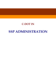
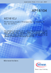
CCS7 Protocol Stack
The CCS7 protocol stack comprises of four layers. With reference to the OSI
7-layer model, the correspondence between the layers is depicted in Fig.1.3.
The functions defined for each layer or level are briefly described in the
following paras.
Level 1
Any node with the capability of handling CCS7 is termed a ‘signalling point’.
The direct interconnection of two signalling points with CCS7 uses one or
more 'signalling link(s)'. Level 1 of the 4-level structure (shown in Fig.1.3)
defines the physical, electrical and functional characteristics of the signalling
link. Defining such characteristics within level 1 means that the rest of the
signalling system (level 2 to 4) can be independent of the transmission
medium adopted. By keeping the interface between levels 1 and 2 constant,
any changes within level 1 do not affect the higher levels. In a digital
environment, usually the physical link is a 64 Kbps channel. This is typically
within a digital transmission system using pulse-code modulation (PCM).
However, other types of link (including analogue) can be used without
affecting levels 2 to 4.
USER'S MANUAL
11
Chapter 1
OSI MODEL
CCS7 PROTOCOL MODEL
OMAP
ASEs
APPLICATION
TCAP
ISUP / TUP
PRESENTATION
SESSION
NULL
TRANSPORT
SCCP
NETWORK
MTP LEVEL 3
DATA LINK
MTP LEVEL 2
PHYSICAL
MTP LEVEL 1
ASE =
ISUP =
MTP =
OMAP =
SCCP =
TCAP =
TUP =
APPLICATION SERVICE ELEMENT
ISDN USER PART
MESSAGE TRANSFER PART
OPERATIONS MAINTENANCE AND ADMINISTRATION PART
SIGNALING CONNECTION PART
TRANSACTION CAPABILITIES APPLICATION PART
TELEPHONE USER PART
FIG. 1.3
CCS7 PROTOCOL ARCHITECTURE
\DESIGN\CCS7-UM\SS7-PA
12
C-DOT CCS7
INTRODUCTION
Level 2
Level 2 defines the functions that are relevant to an individual signalling
link, including error control and link monitoring. Thus, level 2 is responsible
for the reliable transfer of signalling information between two directly
connected signalling points. If errors occur during transmission of the
signalling information, it is the responsibility of level 2 to invoke procedures
to correct the errors. Such characteristics can be optimised without affecting
the rest of the signalling system, provided that the interfaces to levels 1 and
3 remain constant.
Level 3
The functions that are common to more than one signalling link, i.e.
signalling network functions, are defined in level 3 : these include ‘message
handling’ functions and 'signalling network management' functions. When a
message is transferred between two exchanges, there are usually several
routes that the message can take including via a signal-transfer point. The
message-handling functions are responsible for the routing of the messages
through the signalling network to the correct exchange. Signalling network
management functions control the configuration of the signalling network.
These functions include network reconfigurations in response to status
changes in the network. For example, if an exchange within the signalling
network fails, the level 3 of CCS7 can re-route messages and avoid the
exchange that has failed.
Message Transfer Part (MTP)
Levels 1 to 3 constitute a transfer mechanism that is responsible for
transferring information in messages from one signalling point to another.
The combination of level 1 to 3 is known as the message transfer part (MTP).
The MTP controls a number of signalling message links and network
management functions to ensure correct delivery of messages. This means
that the messages are delivered to the appropriate exchange in an
uncorrupted form and in the sequence that they were sent, even under failure
conditions in the network.
Level 4
Level 4 comprises the ‘user parts’. The meaning of the messages transferred
by the MTP and the sequence of actions for a particular application (e.g.
telephony) is defined by the `user parts’. A key feature is that many different
user parts may use the standardised MTP. Hence, if new requirements arise,
that had not been foreseen previously, the relevant user part can be
enhanced (or a new user part derived) without modifying the transfer
mechanism or affecting other user parts. Three user parts have been defined,
the Telephone User Part (TUP), the ISDN User Part (ISUP) and the Data
User Part (DUP). Along with SCCP, which provides end-to-end signalling
capability, MTP constitutes the Network Services Part (NSP) which provides
the Network Layer functionalities of the OSI model. The user parts of NSP
USER'S MANUAL
13
Chapter 1
are Operations and Maintenance Application Part (OMAP) and Mobile
Application Part (MAP).
Signalling Connection Control Part (SCCP)
The Signalling Connection Control Part (SCCP) has the functions of the
network as well as the transport layers of the CCS7 protocol stack. Together
with the MTP, it provides true OSI transport layer capabilities. Unlike MTP
which provides only datagram service, SCCP provides connection-oriented
and connection-less services as well.
Thus, while MTP is sufficient for circuit switched applications like TUP and
ISUP, for non-circuit related applications, such as database querying, the
enhanced addressing capability of SCCP is required. SCCP has a unique
scheme of addressing and routing based on Global Titles. SCCP utilizes the
services of MTP to route its payload from one node to other.
In addition to routing transaction related messages submitted by the
Transaction Capabilities Application Part (TCAP), SCCP also segments and
sequences large TCAP messages to fit into the MTP packet size. At the
distant node it is the responsibility of the peer SCCP to re-assemble the
segmented message.
Transaction Capabilities Application Part (TCAP)
TCAP is an application part in the CCS7 stack and is responsible for
establishing dialogue with remote databases. It carries the data of higher
layers like INAP and MAP and invokes remote operations. An operation at
remote end requires a series of queries and responses as part of a TCAP
dialogue.
Management of a dialogue requires:
♦ Establishing a dialogue
♦ Continuing the dialogue
♦ Terminating the dialogue
♦ Maintaining the integrity of each dialogue in case of multiple dialogue
scenario by assigning unique transaction ids to each dialogue.
♦ Invoking remote operation and managing the operation
TCAP layer is a compound layer in the sense that it is composed of two sublayers, namely, Transaction Sublayer (TSL) and Component Sublayer (CSL).
Transaction sublayer is responsible for establishing, managing and
maintaining the integrity of the dialogue whereas Component sublayer is
responsible for packing the upper layer message into a component and
assigning an invoke ID to the component.
When CCS7 is specified as a signalling system, level 4 specifies a number of
call-control functions. Indeed, the circuit-related mode of CCS7 is so closely
14
C-DOT CCS7
INTRODUCTION
associated with controlling the set-up and release of physical circuits that it
is essential that some aspects of call-control are defined within the user part
specification in order to optimise the procedures that are adopted.
1.5.2.
Application of the Level Structure
The application of the level structure is illustrated in Fig.1.4. Exchanges A
and B are directly connected by speech circuits (denoted by the solid lines
connecting the respective switch blocks). A signalling link is also available
between Exchanges A and B (denoted by the dotted line). It is shown that
level 4 (the user part) is closely associated with the control function of the
exchange.
If the control function of exchange A needs to communicate with the control
function of Exchange B (e.g. to initiate the set-up of a speech circuit between
the exchanges), the control function in Exchange A requests the level 4
functions to formulate an appropriate message. Level 4 then requests the
message-transfer part (level 1 to 3) to transport the message to exchange B.
Level 3 analyses the request and determines the means of routing the
message to exchange B. The message is then transported via levels 2 and 1.
Upon receipt of the message by the MTP of exchange B, levels 1 and 2 deliver
the message to level 3. Level 3 at exchange B recognises that the message
has arrived at the correct exchange and distributes the message to the
appropriate user part at level 4. Level 4 in exchange B then interacts with
the control function to determine the appropriate action and response. If
problems arise in the transmission process between exchanges A and B,
causing message corruption, the level 2 functions are responsible for
detecting the corruption and retransmitting the information. If the signalling
link between exchanges A and B is not available (e.g. link has failed), the
level 3 functions are responsible for re-routing the information through the
signalling network to exchange B.
USER'S MANUAL
15
Chapter 1
EXCHANGE A
EXCHANGE B
SPEECH CIRCUIT
X
X
X
X
SWITCH BLOCK
SWITCH BLOCK
CONTROL
CONTROL
LEVEL 4
LEVEL 4
LEVEL 3
LEVEL 2
LEVEL 3
MTP
MTP
LEVEL 1
LEVEL 2
LEVEL 1
SIGNALLING LINK
FIG. 1.4
APPLICATION OF THE LEVEL STRUCTURE
\DESIGN\CCS7-UM\CCS7-LS
16
C-DOT CCS7
INTRODUCTION
1.5.2.1.
PROTOCOL SPECIFICATIONS
To ensure compatibility between various telephony systems, ITU-T (formerly
CCITT) has specified rules and procedures to be followed by telephony systems.
Common Channel Signalling System No. 7 specified by ITU-T (CCS7) consists of
the international specifications for CCS (Common Channel Signalling)
implementation. The model specific for CCS7 corresponds to the OSI (Open System
Interconnections) model of ISO (International Standards Organisation).
The relevant ITU-T specifications are :
•
The Message Transfer Part (MTP), specified in recommendations Q.701 to Q.709
•
The Signalling Connection Control Part (SCCP), specified in recommendations
Q.711 to Q.714
•
The Transaction Capabilities
recommendations Q.771 to Q.775
•
The Telephone User Part (TUP), specified in recommendations Q.721 to Q.725
•
The ISDN User Part (ISUP), specified in recommendations Q.761 to Q.766
•
The Data User Part (DUP), specified in recommendation Q.741
•
Monitoring and Measurement, specified in recommendations Q.791 and Q.752
•
The Operation and Maintenance Application Part (OMAP), specified in
recommendation Q.795
Application
Part
(TCAP),
specified
in
For detailed specifications, Blue Books [1998] of ITU-T on CCS7 (and subsequent
White Book enhancements) can be referred.
There are certain areas on which ITU-T has left the specification to be framed by
the individual countries. Department of Telecommunications (DOT), the nodal
regulating agency of telephony in India, has specified the implementation of CCS7
in Indian telephone network. It consists of the specifications which are applicable in
the national network and specific recommendations for areas left open by ITU-T, as
well as certain basic services applicable in the Indian context. Some of these are :
•
National Common Channel Signalling Plan (23-330/91-TEC, September 1992)
•
National CCS7 Specifications for Local/Tandem Exchanges (G/CCS – 01/02, SEP
96)
•
National CCS7 Specifications for Transit Exchanges (G/CCS – 02/02, SEP 96)
•
National STP Standards (SP STP 001, September 1994)
•
National SCCP Standards for Large Digital Switching Systems (G/CCS – 03/01,
JUN 94)
In the implementation of CCS7 in C-DOT DSS MAX, the relevant portions of above
mentioned specifications have been used.
USER'S MANUAL
17
Chapter 2.
CCS7 Capability in C-DOT DSS MAX
2.1.
OVERVIEW OF C-DOT DSS MAX ARCHITECTURE
C-DOT DSS MAX family of exchanges employ T-S-T switching architecture and can
be configured by using the following four basic modules (Figure 2.1):
a.
Base Module
b.
Central Module
c.
Administrative Module
d.
Input Output Module
The Base Module (BM) is the basic growth unit of the system. It interfaces the
external world to the switch. The interfaces may be subscriber lines, analog and
digital trunks, CCB and PBX lines, and digital links from remote modules. Each
Base Module can interface upto 2024 terminations. The number of Base Modules
directly corresponds to the exchange size. It carries out majority of call processing
functions and, in a small-exchange application, also carries out operation and
maintenance functions with the help of the Input Output Module.
In Single Base Module (SBM) exchange configuration, the Base Module acts as an
independent switching system and provides connection to upto 1500 lines and 100
trunks. In such configuration, the Base Module directly interfaces with the Input
Output Module for bulk data storage and operations and maintenance functions.
Clock and synchronisation is provided by a source within the Base Module. It is a
very useful application for small urban and rural environments.
With suitable modifications in hardware and software, a Base Module can be
remotely located to form a part of a Remote Switch Unit (RSU) configuration.
Central Module (CM) consists of a message switch and a space switch to provide
inter-module communication and perform voice and data switching between Base
Modules. It provides control-message communication between any two Base
Modules, and between Base Modules and Administrative Module for operation and
maintenance functions.
18
C-DOT CCS7
CCS7 CAPABILITY IN C-DOT DSS MAX
MDF
CM
BM 1
SUBSCRIBER LINES
ANALOG TRUNKS
DIGITAL TRUNKS
BM
n
DIGITAL LINKS
FROM RSUs
ADP
AM
(I/O DEVICES)
IOM
DISK
TAPE
VDU
PRINTER
LEGEND :
BM CM AM IOM ADP MDF RSU n-
BASE MODULE
CENTRAL MODULE
ADMINISTRATIVE MODULE
INPUT OUTPUT MODULE
ALARM DISPLAY PANEL
MAIN DISTRIBUTION FRAME
REMOTE SWITCH UNIT
< 32
FIG. 2.1
C-DOT DSS MAX BASIC ARCHITECTURE
\DESIGN\CCS7-UM\CCS7-SA
USER'S MANUAL
19
Chapter 2
The duplicated Network Synchronisation Controller (NSC) in the CM provides clock
and synchronisation to processing complexes in the switch. It has digital phase
locked (PLL) circuitry for locking to the network reference clock. In free-run made,
it supplies its highly accurate (level 2) clock to the switch.
Administrative Module (AM) performs system-level resource allocation and
processing function on a centralised basis. It performs all the memory and time
intensive call processing support functions and also administration and
maintenance functions. It communicates with the Base Modules via the Central
Module. It supports the Input Output Module for providing man- machine interface.
It also supports an Alarm Display Panel (ADP) for the audio-visual indication of
faults in the system. In SBM configuration, ADP directly communicates with the
Base Processor.
Input Output Module (IOM) is a powerful duplex computer system that interfaces
various secondary storage devices like disk drives, cartridge tape drive and floppy
drive. It supports printers and upto 32 video display units that are used for manmachine communication interface. All the bulk data processing and storage is done
in this module.
Thus, a C-DOT DSS MAX exchange, depending upon its size and application, will
consist of Base Modules (maximum 32 in case of MAX-XL), Central Module,
Administrative Module, Input Output Module and Alarm Display Panel. The Base
Modules can be remotely located or co-located depending on the requirement.
For more details on the hardware and software architecture, please refer to the
document "C-DOT DSS MAX-XL General Description".
2.2.
CCS7 SIGNALLING UNIT MODULE
The ITU-T Signalling System No. 7 (CCS7) capability in C-DOT DSS MAX
exchange is provided in the form of the Signalling Unit Module (SUM). It is a
standalone equipment frame that can be used and retrofitted in any exchange
configuration. Only one such unit is required in an exchange.
The place of SUM in the switch architecture is similar to that of a Terminal Unit
(TU). SUM is equipped in one of the co-located Base Modules in a Terminal Unit
frame position.
Although SUM is a module by itself and contains global resources, it has been
deliberately placed at the front-end in order to make it independent of the switch
configuration. The BM containing the SUM is then called the "home" BM. Figure
2.2 depicts the placement of SUM in C-DOT DSS MAX.
SUM contains a 68010 or 68040 based generic CPU complex and CCS7 signalling
handler terminals. The number of signalling terminals depends upon the signalling
network connectivity and the amount of signalling traffic to be carried.
20
C-DOT CCS7
CCS7 CAPABILITY IN C-DOT DSS MAX
"HOME"
CENTRAL MODULE (CM)
BASE MODULE (BMx)
DTU
SUBSCRIBER
LINES
TIME SWITCHING
OF SIGNALLING
INFO.
SUM
TS
TU
TIME SWITCHING
OF VOICE
INFO.
TU
TSC
ANALOG
TRUNKS
BASE PROCESSOR
SPACE
SWITCHING
DIGITAL TRUNKS
(SIGNALLING LINKS)
DTU
DIGITAL LINKS
TU
TS
FROM RSUs
TU
TU
TSC
BASE PROCESSOR
SSC
BASE MODULE (BMy)
LEGEND:-
AM
APC
TERMINAL INTERFACE CONTROLLER
ADP
GENERIC CPU COMPLEX
IOM
SIGNALLING INFORMATION
VOICE INFORMATION
I/O DEVICES
NOTE :-
IOP
SERVICE CIRCUITS INTERFACES ARE NOT SHOWN
FIG. 2.2
SUM IN C-DOT DSS MAX
USER'S MANUAL
\DESIGN\CCS7-UM\CCS7-SC
21
Chapter 2
The CCS7 protocol stack has been implemented according to ITU-T
Recommendations and Indian National Standards. Message Transfer Part (MTP),
ISDN User Part (ISUP), Signalling Connection Controller Part (SCCP) and
Transanction Capabilities Application Part (TCAP) are available for PSTN, ISDN
and Intelligent Network applications. Monitoring and measurements as per ITU-T
Rec. Q.752 have been implemented. In future, Mobile Application Part (MAP) and
Operations & Maintenance Application Part (OMAP) will be available.
22
C-DOT CCS7
Chapter 3.
SUM Architecture
3.1.
SYSTEM ARCHITECTURE
CCS7 capability in C-DOT DSS MAX exchanges is implemented in the form of the
CCS7 Signalling Unit Module (SUM).
The SUM hardware is packaged into a standard equipment frame. The equipage of
the frame is similar to that of a terminal unit. In a Base Module rack, the SUM
frame can be placed in any Terminal Unit (TU) frame position, i.e. principal frame
or concentration frame position. In case it is equipped in the principal frame
position, it interfaces with the Time Switch via a Terminal Unit Controller (TUC)
on a 128-channel PCM link operating at 8 Mbps. See Fig. 3.1.
However, the SUM can not be equipped with a V5 Unit (VU) in one
concentration chain, i.e. if VU is equipped as the principal TU then SU can
not be concentrated behind it and vice-versa. Also, SUM can not be
equipped in a remote BM (RBM).
Similar to a TU, the SUM has terminal cards i.e. Signalling Handler Module Cards
(SHM). Each SHM card supports upto 8 Protocol Handler (PHC) terminals.
The PHC terminals can be configured as CCS7 protocol terminals, or as C.85
protocol (C-DOT proprietary protocol, a variation of X.25 protocol) terminals for
internal control message communication. Two PHC terminals are configured as
C.85 terminal at the time of SUM initialisation in order to enable code and data
downloading from the Input Output Module. The number of C.85 terminals is
however variable and depends upon the switch configuration.
The communication with the Base Processor of the home BM and between PHC
terminals is handled by the SUM CPU (SU7) complex which is also the central
control of the SUM.
The protocol software is distributed over SHM, SU7 and BPC cards. Table 3-1
depicts the software distribution over various processors.
USER'S MANUAL
23
Chapter 3
`HOME' BM
CM/AM
BMn
(CONTAINS SUM)
(CONTAINS CCS7 CIRCUITS)
TIME SWITCH
SS7
DIGITAL
TRUNKS
TIME SWITCH
SPACE SWITCH
DTU
T
U
C
T
U
C
DTU
TU
T
I
C
T
U
C
DTU
TU
T
I
C
T
U
C
DTU
7SU
T
U
C
T
U
C
DTU
ISUP
TRUNKS
ANALOG
LINES &
TRUNKS
BP
BMS
S
C
I
C
S
C
I
C
SSC
TSC
TSC
BMS
ANALOG
LINES &
TRUNKS
BP
CMS
AP
AM
IOP
IOM
ABBREVIATIONS :LEGEND :CODE/DATA DOWNLOADING PATH
NAILED-UP #7 SIGNALLING LINKS
NAILED-UP INTERNAL MESSAGE (C.85) LINKS
AM
AP
BM
BMS
BP
CM
CMS
DTU
IOM
IOP
SCIC
SSC
SUM
TIC
TSC
TU
TUC
-
ADMINISTRATIVE MODULE
ADMINISTRATIVE PROCESSOR CONTROLLER
BASE MODULE
BASE MESSAGE SWITCH
BASE PROCESSOR
CENTRAL MODULE
CENTRAL MESSAGE SWITCH
DIGITAL TERMINAL UNIT
INPUT OUTPUT MODULE
INPUT OUTPUT PROCESSOR
SERVICE CIRCUITS INTERFACE CONTROLLER
SPACE SWITCH CONTROLLER
SIGNALLING UNIT MODULE
TERMINAL INTERFACE CONTROLLER
TIME SWITCH CONTROLLER
TERMINAL UNIT
TERMINAL UNIT CONTROLLER
FIGURE 3.1
CCS7 SIGNALLING UNIT MODULE
ARCHITECTURE
\DESIGN\CCS7-UM\CCS7-CSU
24
C-DOT CCS7
SUM ARCHITECTURE
3.2.
HARDWARE ARCHITECTURE (FIGURE 3.2)
SUM hardware has been implemented by using two basic types of cards : a backend
duplicated CPU and front-end Signalling Handler Module Cards (SHM). The CPU
(called SU7) cards operate in active/standby mode and interface all the SHM cards
(in n+x redundancy) and off-board memory (BME) as devices on the processor bus.
Each SHM card consists of two processing complexes each with two 68302
processors with inbuilt HDLC controller timer, shared RAM for buffering messages,
EPROM for storing code and static RAM for storing data. The combination of the
microprocessor, HDLC controller and shared RAM constitutes a signalling terminal.
The SHM card provides 8 channels to be used as signalling terminals or I-channels
and another four channels for diagnostic purposes. Outputs of four SHM cards are
multiplexed to offer a 2.048 Mbps stream towards the TUC. Figure 3.2 depicts the
hardware architecture of SUM.
Messages received from the HDLC or messages to be transmitted to the HDLC are
deposited in shared RAM that can be accessed by both the PHC processors as well
as the SU7. The SU7 address and data bus extends to the PHCs to access shared
RAM containing messages. Care is taken in the PHC to avoid contention between
the processors in PHC and CPU accessing the memory. Messages are presented to
the SU7 in FIFO queues corresponding to each channel.
Each PHC terminal is soft configurable to handle CCS7 or C.85 protocols and are
switchable to any data link.
The SU7 card, which is the central control of the SUM, is duplicated and the copies
are attached to the same address and data bus accessing the shared RAM on SHM
cards. At any instant only one SU7 copy is active and other lies in hot standby
mode, i.e. on failure of one copy the other copy takes over immediately. Since the
messages are stored in the shared RAM on the PHCs, messages are not lost and
message handling can proceed unaffected in the event of CPU copy switchover.
3.3.
SOFTWARE ARCHITECTURE
The SUM software is distributed over different processors in SUM and the switch.
While layer 2 protocol functions are completely carried out by the software resident
in the PHC, layer 3 protocol functions are distributed over SU7 and the Base
Processor of the home BM. Call processing functionality (the ISUP) is resident on
the Base Processor. This is depicted in Table 3-1 also. The software subsystems are
described briefly in the following paragraphs.
USER'S MANUAL
25
26
HDLC
LINK
CPU CARD 1
SU7 (CPU)
CARD
COPY 1
SU7 (CPU)
CARD
COPY Ø
CPU CARD Ø
DP
RAM
PROM
8
5
4
1
SHM CARD 8
SHM CARD 7
SHM CARD 2
68302
mP
68302
mP
HDLC
HDLC
HDLC
HDLC
PHC TERMINAL QUEUES
8
7
6
5
4
3
2
1
LEGEND :-
MUX
FIGURE 3.2
SUM HARDWARE ARCHITECTURE
CPU BUS
PROM
PHC COMPLEX 2
DP
RAM
PHC COMPLEX 1
SHM CARD 1
P=
DPRAM =
2.048 Mbps TERMINAL GROUPS
TUC
TO TIME SWITCH
8Mbps LINK
\DESIGN\CCS7-UM\CCS7-HA
DUAL PORT RAM
MICROPROCESSOR MC68302
4
3
2
1
TU I
Chapter 3
C-DOT CCS7
SUM ARCHITECTURE
Table 3-1 CCS7 Software Distribution
Functionality/Subsystem
Hrdware Unit
Level 2
SHM
Level 3
SHM, SU7
ISUP
SU7, Base Processor
Call Processing
Base Processor
Maintenance
Base Processor, SU7, SHM
Administration
Base Processor, Administrative Processor, SU7, SHM
Signalling Message Handler
The message handler is responsible for discrimination of incoming messages, their
distribution to the user parts or routing to other signalling network nodes. The
internal message communication between PHCs, SU7 and home BPC is also
handled by SMH.
See Fig. 3.3 for the place of SMH in the software architecture of SUM. SMH is
resident on PHC as well as SU7.
Signalling Network Manager (SNM)
The Signalling Network Manager constitutes a major part of the level 3 software
resident on the SU7. It is responsible for managing the overall organisation of
signalling paths in the network and takes corrective action in case of failure,
restoration or addition of new links, routes or nodes.
The tasks of signalling network manager are distributed amongst a number of
eternal processes. They maintain and use a common database, containing
informations (both static and dynamic) about the status of links, routes, and nodes,
the network configuration and the connections within the home node. The message
handler for routing of signalling messages uses this information.
The signalling network management processes communicate with one another
using messages, and also with the external world via the message handler. The
‘external world’ comprises the following:
•
Neighbouring nodes in the network - they exchange messages about
reconfiguration of links, blocking the traffic, etc.
•
Local management (maintenance and administration subsystem) - for
exchanging blocking/unblocking, inhibition/uninhibition requests and responses,
and the messages to change path connections within the exchange.
USER'S MANUAL
27
Chapter 3
LEVEL 4
USER
PARTS
LEVEL 2
MESSAGE
TRANSFER
PART
LEVEL 3
MESSAGE TRANSFER PART
SIGNALLING NETWORK FUNCTIONS
SIGNALLING MESSAGE HANDLING
MESSAGE
DISTRIBUTION
MESSAGE
DISTRIBUTION
MESSAGE
ROUTING
SIGNALLING NETWORK MANAGEMENT
SIGNALLING
TRAFFIC
MANAGEMENT
SIGNALLING
ROUTE
MANAGEMENT
SIGNALLING
LINK
MANAGEMENT
CCITT-35730
TESTING AND MAINTENANCE (MESSAGE TRANSFER PART)
SIGNALLING MESSAGE FLOW
INDICATIONS AND CONTROLS
FIG. 3.3
SMH & SNM FUNCTIONS
\DESIGN\CCS7-UM\CCS7-SM
28
C-DOT CCS7
SUM ARCHITECTURE
•
Level 2 – for exchanging messages about signalling terminals’ status and other
protocols.
•
Message handler itself - for exchanging messages for co-ordination of the various
activities.
Operating Systems
The operating system in the SU7 is the proprietary C-DOT DSS Operating System
(CDOS) which provides communication primitives, memory management and
timing services for the user processes. The OS in PHC is the customised TINIX
operating system.
Related software in other processors include :
User Parts
The Telephone User Part (TUP) and ISUP are implemented as part of the call
processing subsystem, which is distributed over different Base Processors. Based on
the ‘half call’ concept, call related characteristics can be categorised either as
incoming or outgoing. As for any other signalling scheme, for CCS7 also, the two
types of characteristics are handled by two terminal processes (TPs) :
•
Incoming Terminal Process (ITP7 for TUP, and, ICUP for ISUP)
•
Outgoing Terminal Process (OTP7 for TUP, and, OGUP for ISUP).
The basic feature of the C-DOT DSS architecture is its capability to interwork with
different signalling schemes. On one end there may be one signalling scheme in the
network while on the other end signalling type may be altogether different. CMR
process facilitates the interworking of different signalling schemes. For CCS7,
problem of interworking arises when on one side of the network there is CCS7 and
the other end is some other. Signalling process translates the message received
from the CCS7 TP and communicates the event to other TP in a form that is
understandable to it. Also, communication received from the non-CCS7 TP is
communicated to CCS7 TP in the format relevant to it.
Maintenance Subsystem
Maintenance subsystem is spread over SU7 and the central processors of the home
BM and the CM. Together these take care of the overall configuration management,
maintenance of SUM and the nailed-up paths, and the management of datalinks to
be used for setting up signalling links.
The ITU-T Recommendations for MTP level 3 assumes some management
functions, which are implementation dependent. In this implementation, these
functions are distributed in BM and AM and form part of CCS7 subsystem. These
functions can be broadly categorised as :
USER'S MANUAL
29
Chapter 3
•
Operator interface for activation/deactivation, blocking/unblocking, inhibiting/
uninhibiting of signalling links and linksets.
•
Data link allocating/deallocation functions
•
Switching functions to provide the switched access to data links
•
Initialisation of the SUM, which includes initial hardware diagnostics,
downloading of code, data and other files, initialisation of database and creation
of other processes in the SU7.
•
Detection and recovery from hardware and software faults
•
Management of terminals and maintenance of PHCs and I-channels
•
Monitoring the health of SUM (including PHCs) and configuration management
•
Diagnostics – automatic and on demand
•
Overload and congestion control
•
Running audits on the database periodically and on demand
Administration System
The administration subsystem coordinates the following activities :
•
Execution of the administration related man-machine command (for addition,
deletion and modification of the status of various resources), and the
maintenance related man machine commands for testing and configuration
management.
•
Generation of alarms and reports for the operator
•
Generation of CCS7 related traffic reports
Database Subsystem
The data related to the CCS7 resources (signalling links and terminals, linksets,
routes, route sets, point codes and other network specific data), system parameters
and network configuration data utilised by CPU processes is kept in the CPU
memory and maintained by its own database routines. Routines are available for
insertion, deletion, selection, updation and modification of data.
A part of this data is maintained in a different format in the central database in BP,
and AP as well, which is accessed by concerned processes using the standard
database routines. These data are downloaded and modified through man-machine
commands.
30
C-DOT CCS7
Chapter 4.
Call Processing
4.1.
INTRODUCTION
Building upon the discussion on the SUM architecture in the last chapter, in this
chapter, the hardware - software interactions are illustrated with the help of ISUP
call handling procedures.
In C-DOT DSS MAX ISUP call handling is different from non-ISUP call handling.
This is so because of the SUM hardware and software which now have to
participate in call handling. Apart from this the general philosophy of call
processing remains the same.
In the following sections, the processes of handling an ISUP incoming- terminating
call and an ISUP transit call is described. Originating - outgoing call flow is
essentially similar to the incoming - terminating call flow described below.
4.2.
ISUP CALL MESSAGE SEQUENCE
The signalling message sequence during the handling of a successful and
unsuccessful ISUP call is depicted in Fig. 4.1 and 4.2. The discussion in subsequent
sections is based upon this information.
4.3.
ISUP TERMINATING CALL
Setup Phase
When an ISUP call originates on an ISUP trunk, the Status Control Process (SCP)
checks the busy/free status of the trunk circuit (i.e., CIC).
If the circuit is free, an incoming trunk terminal process – ICUP (Incoming ISDN
User Part) – is created for handling the ISUP protocol. Once this process is created
the SCP forwards the Initial Address Message (IAM) received from preceding
exchange to it. ICUP extracts the called party number from IAM and performs
preliminary digit analysis (i.e. whether the call is terminating in the same
exchange or it has to be transited etc.). When the call is terminating in the
exchange, it collects all the digits of the called party and goes for routing of the call
in order to determine the destination of the call. For the transit case, refer to the
next section.
USER'S MANUAL
31
32
LEGEND :-
SUBSCRIBER
INTERFACE
LINE CONDITIONS
ISUP MESSAGE
INBAND TONE
NO VOICE PATH
ANM
REL
ANM
REL
RLC
RBT
ACM
ACM
RBT
(IN-BAND)
(IN-BAND)
ISUP
INTERFACE
TERMINATING
SUBSCRIBER
SUB. B
ON-HOOK
OFF-HOOK
RING
SUBSCRIBER
INTERFACE
TERMINATING EXCHANGE
\DESIGN\CCS7-UM\CCS7-IS
FIG. 4.1
SUCCESSFULL ISUP CALL : MESSAGE SEQUENCE
VOICE PATH THROUGH IN BOTH THE DIRECTIONS
VOICE PATH THROUGH IN BACKWARD DIRECTION
PARTY
CALL CLEARED
BY CALLING
ON-HOOK
RBT
CRT
SAM
SAM
DIGITS
SS7
IAM
ISUP
INTERFACE
IAM
ISUP
INTERFACE
TRANSIT EXCHANGE
DIGITS
DIGITS
DT
SS7
ISUP
INTERFACE
ORIGINATING EXCHANGE
OFF-HOOK
ORIGINATING
SUBSCRIBER
SUB. A
Chapter 4
C-DOT CCS7
LEGEND :-
SUBSCRIBER
INTERFACE
USER'S MANUAL
LINE CONDITIONS
ISUP MESSAGE
INBAND TONE
NO VOICE PATH
RLC
RLC
SUBSCRIBER
INTERFACE
CALLED
SUB.
BUSY
ANALOG
SUBSCRIBER
\DESIGN\CCS7-UM\CCS7-IU
FIG. 4.2
UNSUCCESSFUL ISUP CALL : MESSAGE SEQUENCE
VOICE PATH THROUGH IN BACKWARD DIRECTION
ON-HOOK
BT
REL
DT
ISUP
INTERFACE
REL (SUBS. BSY.)
SAM
SAM
DIGITS
ISUP
INTERFACE
IAM
ISUP
INTERFACE
IAM
ISUP
INTERFACE
DIGITS
DIGITS
DT
OFF-HOOK
ORIGINATING
SUBSCRIBER
CALL PROCESSING
33
Chapter 4
Ringing Phase
In the terminating exchange, it is then checked whether the called party is free or
busy. If the called party is free, then ring is fed to the called subscriber. Path is
switched in the backward chain towards the calling party by sending an Address
Complete Message (ACM) to the preceding exchange. After switching the path, Ring
Back Tone (RBT) is fed to the calling subscriber.
The charging information is extracted for the call based on the incoming trunk
group category and the call party category and passed to ICUP. If in the charging
information it is indicated that this exchange has to do the charging, ICUP
generates the Charge (CRG) message and sends it to the preceding exchange, prior
to sending the ACM, so that the charging of the call can be done at the originating
exchange upon receipt of answer.
Conversation Phase
When the called subscriber answers the call, Answer Message (ANM) is sent to the
preceding exchange to notify the called party's condition to the calling subscriber.
Release Phase
If the calling party releases the call, ICUP receives Release (REL) message from the
preceding exchange. It records the case of failure and replies with Release Complete
(RLC) message to the preceding exchange. The call details are then sent to the
relevant administration processes for post-processing.
4.4.
ISUP TRANSIT CALL
Setup Phase
When a call originates on an ISUP trunk, SCP checks the free/busy status of the
trunk circuit (i.e., CIC).
If the circuit is free, then an incoming trunk terminal process, ICUP (Incoming
ISDN user part), is created for catering to ISUP protocol at the incoming end. Once
this process is created SCP forwards the Initial Address Message (IAM) received
from preceding exchange to it. ICUP extracts the called party number from IAM
and performs preliminary digit analysis (to determine whether the call is
terminating in the same exchange or is outgoing from the exchange etc.). When the
called party is outgoing from this exchange, then called party digits are used for
determining the trunk group on which the call is to be routed. It is then checked
whether free trunk circuits are available in the trunk group. After a free circuit is
selected on the outgoing route, in outgoing trunk, terminal process OGUP
(Outgoing ISDN User Part) is created for catering to ISUP protocol at the outgoing
end and the IAM received from the preceding exchange is forwarded to the
succeeding exchange on the signalling link and ACM timer is started.
Ringing Phase
34
C-DOT CCS7
CALL PROCESSING
For an outgoing call, charging information is defined on the route for the incoming
trunk group category and this information is passed to ICUP.
When ACM is received from the succeeding exchange, voice path is switched and, if
the charge data indicates that this exchange has to do the charging, the CRG
message is generated and sent to the preceding exchange followed by ACM.
Conversation Phase
When the called subscriber answers the call, ANM received from the succeeding
exchange is forwarded to the preceding exchange to notify the called party's
condition to the calling subscriber.
Release Phase
If the calling party releases the call, then ICUP receives REL from the preceding
exchange. The cause of failure is recorded and RLC is sent to the preceding
exchange. To the succeeding exchange, the REL message received is forwarded. On
getting RLC the call details are sent to the relevant administration process for postprocessing.
USER'S MANUAL
35
Chapter 5.
Command Directory
5.1.
INTRODUCTION
Commands are the tools that can be used to observe, record, manipulate and
display exchange data. For the purpose of incorporating requirements specific to
CCS7 implementation, administration and maintenance, commands have been
added to the existing MML command set of C-DOT DSS MAX. CCS7 administration
commands are grouped under two classes in the CRP Administration commands
menu.
Class 31
Number 7 Update Commands
Class 32
Number 7 Display Commands
Similarly, CCS7 maintenance commands are also grouped under the following two
classes in the CRP Maintenance commands menu.
Class 12
Number 7 Maintenance Update Commands
Class 13
Number 7 Maintenance Display Commands
Additionally, ISUP charging related update and display commands are available in
classes 40 & 41 respectively.
5.2.
COMMANDS DIRECTORY
Command directory serves the function of a central reference point for all the
commands. By looking at the various entries in the directory the operating
personnel get an idea of the function performed by a command, its mnemonic and
the position defined parameters required for its execution.
The directory is divided into four parts corresponding to the four CCS7 command
classes and two addition classes, which contain ISUP charging related commands.
Please note that through all the commands and their parameters have
been described in Chapter 5 & 6, all the commands may not be available in
a particular software release.
36
C-DOT CCS7
COMMAND DIRECTORY
5.3.
COMMAND FLOW
Irrespective of the command, all the commands when executed follow a similar
pattern of man-machine interaction. Command flow is the interaction between the
operating personnel (man) and the software, more specifically, the Command
Recognition Process (CRP) (machine).
As an illustration, the command flow for Create Circuit Group Set (CRE-CGS)
command is given in the following paras.
1.
At the CRP prompt (>), either give the command CRE-CGS or the menu path
for this command, i.e. 1 (Administration Main Menu), 31 (Number 7 Update
Commands 8) (Create Circuit Group Set). The path will be specified by typing
MENU 1 31 8.
Yet another method would be to traverse the menus and choose the
appropriate option. In any case, let us assume that the command has been
correctly issued.
2.
'Security Checks' are performed by CRP, i.e. whether the operator has the
authority to issue this command. This authority is granted to an operator
while adding a new operator via ADD-OPR command.
3.
Parameter Entry Form is displayed if security check has been passed. The
form contains:
♦ The command mnemonic, command name and all the position-defined
parameters required for executing the command.
♦ Non-essential parameters, i.e. to which a default value is attached, are
shown enclosed in square brackets ([ ]) while essential parameters are
without brackets. For example, in this case, all the parameters except
SIG-NW and USR-PART are essential (mandatory) parameter.
4.
User enters parameter values as desired. Error messages will be displayed
for illegal entries.
Online 'Help' is available for each parameter and can be accessed by typing ‘h'
and 'CR' (Carriage Return) while the cursor is at the desired parameter.
5.
Option to Repeat/Terminate/Execute (R/T/E) the command with the given
input parameters will now be displayed.
♦ User enters the "Execute" i.e. "E" option. The system will respond by
displaying the message: Executing ....
Now, the Command Execution Process (CEP) validates the parameters
entered.
If CEP detects any error, the command is rejected and CRP displays an error
message. The error message contains error number, error statement, entity
USER'S MANUAL
37
Chapter 5
id and error dictionary reference. Let us assume that parameter validation
was successful.
6.
Since the command has been executed successfully, CRP will display output
results in the form of "Output Forms" which may occupy one or more VDU
screen and/or printer pages. The results will be sent to VDU, printer, or both
depending upon the option already chosen by the operator via CHG-OUTDEV command.
Class 31: Number 7 Administration Update Commands
S.No.
38
Command
Mnemonic
Command Name
Position Defined Parameters
1.
CRE-SRS
Create a Signalling Relation
SRS-NUM, DPC, HI-RTBL, [LO-RTBL],
[SSN-LST]
2.
MOD-SRS-CHAR
Modify a Signalling Route
Set
SRS-NUM, [HI-RTBL], [LO-RTBL],
[SSN-LST].
3.
DEL-SRS
Delete Signalling Route Set
SRS-NUM
4.
CRE-SPC
Create Signal Point Code for
Exchange
[SIG-NW], SPC-LST
5.
DEL-SPC
Delete SPC For This
Exchange
[SIG-NW], SPC-LST
6.
CRE-LS
Create a Link Set
LS-NUM, LSB-NUM, [MNAC-LN],
[MXAV-LN], [MNAV-LN], EC-OPTN,
[MXMS-RB], [MXOC-RB],
PC-LST, LOG-LNK, [DAT-LNK]
7.
DEL-LS
Delete Link Set
LS-NUM
8.
CRE-CGS
Create Circuit Group Set
For This Exchange
CGS-NUM, CGS-NAME,SELF-PC,
DEST-PC, [SIG-NW], [USR-PART]
9.
DEL-CGS
Delete Circuit Group Set
[CGS-NUM], [CGS-NAME]
10.
CRE-LSB
Create Link Set Bundle For
This Exchange
LSB-NUM, [CGS-NUM], [CGS-NAME],
LM-MTHD, MX-MSGSZ, [STP-USER],
[DEST-PCS]
11.
DEL-LSB
Delete Link Set Bundle
LSB-NUM
12.
MOD-LSB-CHAR
Modify Link Set Bundle
Characteristics
LSB-NUM, [STP-USER],
[DEST-PCS]
13.
ADD-DEL-LNK
Add or Delete Link
LS-NUM, OPR-TYP,
[LOG-LNK], [DAT-LNK]
14.
MOD-LS-CHAR
Modify Link Set
Characteristics
LS-NUM, [MNAC-LNK], [MXAV-LN],
[MNAV-LN], [PC-LST]
15.
CRE-GT
Create Global Title
GT, PC, [SIG-NW], SSN, [NEW-NAI],
C-DOT CCS7
COMMAND DIRECTORY
S.No.
Command
Mnemonic
Command Name
Position Defined Parameters
Translation
[NEW-ADR], [RTIND]
16.
MOD-GT-CHAR
Modify a Global Title
GT, PC, [SIG-NW], SSN,
[NEW-NAI], [RTIND]
17.
DEL-GT
Delete Global Title
Translation
GT
CCS7 COMMANDS DIRECTORY (Contd.)
CLASS 32: Number 7 Administration Display Commands
S.No.
Command Mnemonic
Command Name
Position Defined Parameters
1.
DISPL-SRS
Display Signalling Route Set
Information
SRS-NUM
2.
DISPL-SPC
Display Signal Point Code
No parameters required
3
DISPL-LS
Display Link Set
LS-NUM
4.
DISPL-CGS
Display Circuit Group Set
[GS-NUM], [CGS-NAME]
5.
DISPL-LSB
Display Link Set Bundle
LSB-NUM
6.
DISPL-CGS-NUM-NAME
Display Circuit Group Set
Number to Name Mapping
[GS-NUM], [CGS-NAME]
7.
DISPL-GT
Display Global Title
Translation
GT
CLASS 12: Number 7 Maintenance Update Command
S.No.
Command Mnemonic
Command Name
Position Defined Parameters
1.
TST-SGNL-LNK
Test Signal Link
LSB-NUM, LOG-LNK
2.
MOD-LS-STS
Modify Link Set Status
LS-NUM, ACTION
3.
MOD-LNK-STS
Modify Link Status
LSB-NUM, LOG-LNK, ACTION
4.
MOD-BLK7-STS
Modify Block 7 Status
BLK-TYP, TEN
USER'S MANUAL
39
Chapter 5
CLASS 13: Number 7 Maintenance Display Commands
S.No.
Command Mnemonic
Command Name
Position Defined Parameters
1.
DISPL-LS-STS
Display Link Set Status
[LS-NUM]
2.
DISPL-NET-STS
Display Network Status
[NET-ID], [PC-NUM]
3.
DISPL-BLK7-STS
Display Block 7 Status
TEN
CLASS 30: Charge Calendar Management Update
S.No.
Command Mnemonic
1.
MOD-CHB-CRG
Command Name
Modify Charge Band - Charge
Rate Number Association
Position Defined Parameters
OPR-TYP, CRG-BND,
[CRG-RTN]
CLASS 41: Charge Calendar Management Display
S.No.
1.
40
Command Mnemonic
DISPL-CHB-CRG
Command Name
Display Charge Band - Charge
Rate Association
Position Defined Parameters
[CRG-BND]
C-DOT CCS7
Chapter 6.
Parameters Description
6.1.
INTRODUCTION
On issuing a command with valid mnemonic and syntax, the system responds by
displaying a parameter entry form in which the parameters required for execution
of that command are to be specified by the operator. Parameters are variables that
identify and contain a piece of necessary information to execute a command.
Although online 'help' is available on the parameter entry form, it is very important
for the operating personnel to understand the correct application of each parameter.
Some of the parameters are used in more than one command. In the parameter
description to follow, such parameters are discussed only once alongwith necessary
qualifying remarks. Parameter description for each parameter is covered under the
following subheads:
6.2.
PARAMETER NAME
:
Name of the parameter
MNEMONIC
:
Address code in the form of a pronounceable word
TYPE
:
ASCII, numeric or logical, i.e. type of data acceptable
POSSIBLE VALUES
:
A set of values and/or range acceptable
DEFAULT VALUE
:
The value automatically assigned by the system if the operator does
not assign any value i.e. just presses the <Return> key
REMARKS
:
Some more information regarding special attributes of the parameter
and their usage
PARAMETERS DESCRIPTION
On the proceeding pages, all the parameters used by CCS7 administration and
maintenance commands are described in the format described above in section 3.1.
USER'S MANUAL
41
Chapter 6
6.2.1.
ACTION
PARAMETER NAME
:
Action
MNEMONIC
:
ACTION
TYPE
:
10 ASCII
POSSIBLE VALUES
:
1.
2.
3.
4.
5.
6.
DEFAULT VALUE
:
None. Essential Parameter.
REMARKS
:
In MOD-LNK-STS command, this parameter is used to specify the
action to be done on the link.
6.2.2.
Activate
Deactivate
Block
Unblock
Inhibit
Uninhibit
BLK-TYP (Block Type)
PARAMETER NAME
:
Block Type
MNEMONIC
:
BLK-TYP
TYPE
:
7 ASCII
POSSIBLE VALUES
:
1. Block
2. Unblock
3. Reset
Range or set not allowed.
DEFAULT VALUE
:
None. Essential Parameter.
REMARKS
:
Type of blocking action to be done on the #7 CICs. Reset option is
used to send Reset Circuit (RSC) message for one or more CICs. It is
a useful option that is used specially when the distant node is not
honoring Group Reset (GRS) message from the local node.
6.2.3.
CGS-NAME (Circuit Group Set Name)
PARAMETER NAME
:
Circuit Group Set Name
MNEMONIC
:
CGS-NAME
TYPE
:
10 ASCII
POSSIBLE VALUES
:
Any ASCII string of maximum length 10. Range or set not allowed.
DEFAULT VALUE
:
Non. Essential parameter.
REMARKS
:
CGS name is used to give an easily remembered identity to the CGS
in addition to the CGS-NUM. For example, CGS between Delhi and
Calcutta may be named as ‘DEL-CAL’.
42
C-DOT CCS7
PARAMETERS DESCRIPTION
6.2.4.
CGS-NUM (Circuit Group Set Number)
PARAMETER NAME
:
Circuit Group Set Number
MNEMONIC
:
CGS-NUM
TYPE
:
2 Numeric
POSSIBLE VALUES
:
1 to 64. Range or set not allowed.
DEFAULT VALUE
:
None. Essential parameter
REMARKS
:
The identification of trunk group/s which are served by common
signalling links. CGS represents the identity of voice circuits in the
CCS7 network and does the association between the voice and
signalling networks.
6.2.5.
CRG-BND (Charge Band)
PARAMETER NAME
:
Charge Band
MNEMONIC
:
CRG-BND
TYPE
:
3 Numeric
POSSIBLE VALUES
:
0 to 255
DEFAULT VALUE
:
‘None’, when it is an essential parameter., and, ‘All’ when it is not
essential.
REMARKS
:
Charge Band is associated with a charge rate number according to
which CCS7 calls will be charged. Charge band will be used for
charging only if such charging method is defined in the CCS7 trunk
group.
6.2.6.
DAT-LNK (Data Link)
PARAMETER NAME
:
Data Link
MNEMONIC
:
DAT-LNK
TYPE
:
Numeric string with 5 subfields separated by ‘-‘. Format is B-R-F-S-C.
The description of fields is same as for TEN given in section 3.2.8.
But here PCM number (D) is not used.
POSSIBLE VALUES
:
1-1-1-1-1 to 32-3-6-26-32. Set allowed.
DEFAULT VALUE
:
None. Essential parameter.
REMARKS
:
Signalling data link identifies the channel on the digital transmission
medium, which is to be used as the signalling data link. The data
link chosen should be the same by both the ends of the link.
USER'S MANUAL
43
Chapter 6
6.2.7.
DEST-PC/DEST-PCS (Destination Point Code/s)
PARAMETER NAME
:
Destination Point Code/s.
MNEMONIC
:
DEST-PC, DEST-PCS
TYPE
:
5 Numeric.
POSSIBLE VALUES
:
0 to 214-1. i.e., 0 to 16383. Range not allowed
DEFAULT VALUE
:
No default value in some commands. Else 65534, i.e. none defined.
REMARKS
:
The destination point code for a CGS. In case of LSB, since multiple
nodes can be reached via one LSB (consider the entire route between
two non-adjacent point codes), more than one point codes can be
defined.
6.2.8.
DPC (Destination Point Code)
PARAMETER NAME
:
Destination Point Code
MNEMONIC
:
DPC
TYPE
:
5 Numeric
POSSIBLE VALUES
:
0 to 214-1, i.e. 0 to 16383. Range or set not allowed.
DEFAULT VALUE
:
None. Essential Parameter.
REMARKS
:
The point code of the destination of the outgoing message is called
DPC.
6.2.9.
EC-OPT (Error Correction Option)
PARAMETER NAME
:
Error Correction Option
MNEMONIC
:
EC-OPT
TYPE
:
5 ASCII
POSSIBLE VALUES
:
1. BASIC
2. PCR.
Range or set not allowed.
DEFAULT VALUE
:
None. Essential parameter.
REMARKS
:
Defines the error correction method for a link set. Basic option is used
to terrestrial link whereas PCR (Preventive Cycle Retransmission) is
used for long delay routes, e.g. satellite routes.
6.2.10.
GT (Global Title)
PARAMETER NAME
44
:
Global Title
C-DOT CCS7
PARAMETERS DESCRIPTION
MNEMONIC
:
GT
TYPE
:
ASCII or Numeric (4 fields)
POSSIBLE VALUES
:
(Subfield 1) T Type
:
None, TYPE1, TYPE254, TYPE253
(Subfield 2) NUMPLAN:
NONE, UNKNOWN, ISDN, SPARE2,
DATA-TELEX, MAR-MOBILE,
LAND-MOBILE, ISDN-MOBILE.
(Subfield 3) NAI
NONE, SUBS, RESN, MSN, IN
:
(Subfield 4) ADR
:
Numeric range 9999 9999 9999 9999
9999
DEFAULT VALUE
:
None
REMARKS
:
Global title is used for SCCP addressing. GT specifies the Translation
Type i.e. T TYPE, the Numbering Plan being used after translation NUM-PLAN, and the Nature of address indicator. ADR (adress)
indicates the remote DPC address to which the SCCP messages will
be routed if routing indicator is DPC + SSN.
6.2.11.
HI-RTBL (High (Priority) Route Table)
PARAMETER NAME
:
High (Priority) Route Table
MNEMONIC
:
HI-RTBL
TYPE
:
2 Numeric
POSSIBLE VALUES
:
1 to 64. Set allowed.
DEFAULT VALUE
:
None. Essential parameter.
REMARKS
:
In a signalling routset, the set of high priority routes.
6.2.12.
LM-METHOD (Link Management Method)
PARAMETER NAME
:
Link Management Method
MNEMONIC
:
LM-METHOD
TYPE
:
9 ASCII string
POSSIBLE VALUES
:
1.
2.
3.
DEFAULT VALUE
:
None. Essential Parameter.
REMARKS
:
Generally LM-BASIC method is used.
USER'S MANUAL
LM-BASIC
LM-SECOND
LM-THIRD
45
Chapter 6
6.2.13.
LO-RTBL (Low Priority Route Table)
PARAMETER NAME
:
Low (Priority) Route Table
MNEMONIC
:
LO-RTBL
TYPE
:
2 Numeric
POSSIBLE VALUES
:
1 to 64. Set allowed.
DEFAULT VALUE
:
None. Essential Parameter.
REMARKS
:
In a signalling route set, the set of low priority routes. These routes
will be selected if the high priority routes are unavailable.
6.2.14.
LOG-LNK (Logical Link)
PARAMETER NAME
:
Logical Link
MNEMONIC
:
LOG-LNK
TYPE
:
2 Numeric
POSSIBLE VALUES
:
0 to 15. Range or set not allowed.
DEFAULT VALUE
:
None. Essential Parameter..
REMARKS
:
It is the logical identity of the link in the linkset.
6.2.15.
LS-NUM (Link Set Number)
PARAMETER NAME
:
Link Set Number
MNEMONIC
:
LS-NUM
TYPE
:
2 Numeric
POSSIBLE VALUES
:
1 to 64. Range or set not allowed.
DEFAULT VALUE
:
None. Essential parameter.
REMARKS
:
Link set is a set of signalling links of the same CGS.
Link set number is used to identify a signalling link set in a link set
bundle. Link set is a set of signalling links between adjacent nodes.
The links within the set are logically numbered. The error correction
option, i.e. Basic or PCR, is same of all links in link set.
46
C-DOT CCS7
PARAMETERS DESCRIPTION
6.2.16.
LSB-NUM (Link Set Bundle Number)
PARAMETER NAME
:
Link set Bundle Number
MNEMONIC
:
LSB-NUM
TYPE
:
2 Numeric
POSSIBLE VALUES
:
1 to 64. Range of set not allowed.
DEFAULT VALUE
:
None
REMARKS
:
LSB, also called combined link set, is a set of all signalling link sets
between two adjacent signalling points. The link sets in a LSB have
the same link management method, maximum message size and list
of STP users and destination point codes. LSB has only a logical
significance.
6.2.17.
MNAC-LN (Minimum Active Links)
PARAMETER NAME
:
Minimum Active Links
MNEMONIC
:
MNAC-LN
TYPE
:
2 Numeric
POSSIBLE VALUES
:
1 to 16. Range or set not allowed.
DEFAULT VALUE
:
1
REMARKS
:
It is the minimum active links threshold in a link set. If the number
of active links falls below this value, the maintenance system is
alerted via a threshold cross report. The system will try to activate
more links in order to reach this threshold.
6.2.18.
MNAV-LN (Minimum Available Links)
PARAMETER NAME
:
Minimum Available Links
MNEMONIC
:
MNAV-LN
TYPE
:
2 Numeric
POSSIBLE VALUES
:
1 to 16. Range or set not allowed.
DEFAULT VALUE
:
1
REMARKS
:
It is the minimum number of links available for carrying traffic in a
link set.
USER'S MANUAL
47
Chapter 6
6.2.19.
MX-MSG-SZ (Maximum Message Size)
PARAMETER NAME
:
Maximum Message Size
MNEMONIC
:
MX-MSG-SZ
TYPE
:
7 ASCII
POSSIBLE VALUES
:
1.
2.
3.
DEFAULT VALUE
:
None. Essential parameter.
REMARKS
:
Defines the maximum signalling information field (SIF) size to be
handled. Generally in ISUP implementation, DATA272 i.e., 272
octets SIF size is used. SIF contains routing label and actual
signalling information.
6.2.20.
DATA62
DATA272
DYNAMIC
MX-OC-RB (Maximum Octets in Retransmission Buffer)
PARAMETER NAME
:
Maximum Octets in Retransmission Buffer
MNEMONIC
:
MX-OC-RB
TYPE
:
5 Numeric.
POSSIBLE VALUES
:
1 to 65535. Range or set not allowed.
DEFAULT VALUE
:
None. Essential parameter.
REMARKS
:
Defines the maximum number of message octets to be retained in the
retransmission buffer. MXMS-RB and MXOC-RB are used in tandem
to control the levels of retransmission buffers.
6.2.21.
MXAV-LN (Maximum Available Links)
PARAMETER NAME
:
Maximum Available Links
MNEMONIC
:
MXAV-LN
TYPE
:
2 Numeric
POSSIBLE VALUES
:
1 to 16. Range or set not allowed.
DEFAULT VALUE
:
0 (zero)
REMARKS
:
It is the maximum number of links available for carrying traffic in a
link set.
48
C-DOT CCS7
PARAMETERS DESCRIPTION
6.2.22.
MXMS-RB (Maximum MSU in Retransmission)
PARAMETER NAME
:
Maximum MSUs (Message Signalling Unit) in Retransmission
Buffers
MNEMONIC
:
MXMS-RB
TYPE
:
5 Numeric
POSSIBLE VALUES
:
1 to 65535. Range or set not allowed.
DEFAULT VALUE
:
127.
REMARKS
:
Defines the maximum of MSUs to be retained in retransmission
buffers. If acknowledgement is not received within a specific period or
a negative acknowledgement is received, appropriate number of MSU
are retransmitted from the buffer.
6.2.23.
NEW-ADR (New Address)
PARAMETER NAME
:
New Address digits after GT translation
MNEMONIC
:
New-ADR
TYPE
:
Numeric
POSSIBLE VALUES
:
Range 9999 9999 9999 9999 9999
DEFAULT VALUE
:
NONE
REMARKS
:
This specifies the new address after GT translation. This will be used
only if the old GT address is to be converted to a new address
6.2.24.
NET-ID (Network Identification)
PARAMETER NAME
:
Network Identification
MNEMONIC
:
NET-ID
TYPE
:
7 ASCII
POSSIBLE VALUES
:
1.
2.
DEFAULT VALUE
:
NW-NAT
REMARKS
:
It identifies the national or international network within which the
connectivity status of the local mode is to be interrogated.
USER'S MANUAL
NW-NAT (National network)
NW-INAT (International network)
49
Chapter 6
6.2.25.
NEW-NAI (New Nature of Address Indicator)
PARAMETER NAME
:
New NAI after GT translation
MNEMONIC
:
New-NAI
TYPE
:
ASCII or Numeric
POSSIBLE VALUES
:
NONE, SUBS, RESN, MSN, IN
DEFAULT VALUE
:
NONE
REMARKS
:
This specifies the new NAI after GT translation.
6.2.26.
NUM-FLAG (Number of Flags between signalling units)
PARAMETER NAME
:
Number of flags between signalling units.
MNEMONIC
:
NUM-FLAG
TYPE
:
Number (0 to 15)
DEFAULT VALUE
:
0
REMARKS
:
This field is used to increase or decrease the number of flags between
two signalling units of CCS7 message.
6.2.27.
OPR-TYP (Operation Type)
PARAMETER NAME
:
Operation Type
MNEMONIC
:
OPR-TYP
TYPE
:
3 ASCII
POSSIBLE VALUES
:
1.
2.
DEFAULT VALUE
:
None. Essential Parameter.
REMARKS
:
In ADD-DEL-LNK command, the operation type. Choose ADD if a
link is to be added to a linkset and DEL if is to be deleted.
50
ADD
DEL
C-DOT CCS7
PARAMETERS DESCRIPTION
6.2.28.
PC- LST (Point Codes List)
PARAMETER NAME
:
Point Codes List
MNEMONIC
:
PC-LST
TYPE
:
5 Numeric
POSSIBLE VALUES
:
0 to 16383. Set allowed.
DEFAULT VALUE
:
None. Essential parameter.
REMARKS
:
It is the list of point codes for which signalling messages are carried
by a signalling link set.
6.2.29.
PC-NUM (Point Code Numbers)
PARAMETER NAME
:
Point Code Numbers
MNEMONIC
:
PC-NUM
TYPE
:
5 Numeric
POSSIBLE VALUES
:
0 to 16383. Set allowed.
DEFAULT VALUE
:
None. Essential parameter.
REMARKS
:
Used for specifying the set of point codes in a given type of network
(NAT or INAT whose connectivity status to this node is to be
interrogated.
6.2.30.
RTIND (Routing Indicator)
PARAMETER NAME
:
Routing Indicator
MNEMONIC
:
RTIND
TYPE
:
ASCII or Numeric
POSSIBLE VALUES
:
1. DPCSSN
2. GT
DEFAULT VALUE
:
DPCSSN
REMARKS
:
This parameter specifies the routing mechanism to be used by INAP
or SCCP messages. If Routing indicator is GT then GT translation
will be used. If DPCSSN is used then the routing will be done on the
DPC & SSN specified in the GT.
USER'S MANUAL
51
Chapter 6
6.2.31.
SELF-PC (Self Point Code)
PARAMETER NAME
:
Self Point Code
MNEMONIC
:
SELF-PC
TYPE
:
5 Numeric
POSSIBLE VALUES
:
0 to 214-1 i.e. 0 to 16383. Range or set not allowed.
DEFAULT VALUE
:
None. Essential parameter.
REMARKS
:
Refers to the particular point code of the node which is used for
defining a particular signalling relation.
6.2.32.
SIG-NW (Signalling Network Identification)
PARAMETER NAME
:
Signalling Network Identification
MNEMONIC
:
SIG-NW
TYPE
:
13 ASCII
POSSIBLE VALUES
:
1. NW-INAT,
2. NW-INAT-SPARE
3. NW-NAT
4. NW-NAT-SPARE
Range or set not allowed
DEFAULT VALUE
:
NW-NAT
REMARKS
:
It is a 2 bit code that indicates the signalling network to which the
node belongs. The network could be national (NAT) or international
(INAT). Spare codes are provided to accommodate multiple national
or international network. By this approach, the number of signalling
point codes can be increased in a network.
52
C-DOT CCS7
PARAMETERS DESCRIPTION
6.2.33.
SPC-LST (Self Point Code List)
PARAMETER NAME
:
Self Point Code List
MNEMONIC
:
SPC-LST
TYPE
:
5 Numeric
POSSIBLE VALUES
:
0 to 214-1 i.e. 0 to 16383. Set allowed
DEFAULT VALUE
:
None. Essential parameter.
REMARKS
:
The list of point codes assigned to an exchange which is node in the
CCS7 signalling network. Similar to exchange code in the voice
network.
6.2.34.
SRS-NUM (Signalling Route Set Number)
PARAMETER NAME
:
Signalling Route Set Number
MNEMONIC
:
SRS-NUM
TYPE
:
2 Numeric
POSSIBLE VALUES
:
1 to 64. Range or set not allowed.
DEFAULT VALUE
:
None. Essential parameter.
REMARKS
:
SRS is the set of signalling routes defined between two nodes.
6.2.35.
SSN-LST (Subsystem Number List)
PARAMETER NAME
:
Subsystem Number List
MNEMONIC
:
SSN-LST
TYPE
:
ASCII or Numeric
DEFAULT VALUES
:
NONE-65535-NONE-NONE
REMARKS
:
This parameter is used for identifying subsystems. It has the
following 4 fields:
Subfield 1: User parts, Possible values NONE, SCMG (SCCP
Management), INAP (Intelligent Network Application
part), ISUP (ISDN user part).
Subfield 2: Backup DPC. Used only when SCP are mated. It is used
to specify the backup DPC number.
Subfield 3: Backup DPCs Nature of network
Subfield 4: Backup SSN id.
USER'S MANUAL
53
Chapter 6
6.2.36.
STP-USER (Signalling Transfer Point Users)
PARAMETER NAME
:
STP Users
MNEMONIC
:
STP-USER
TYPE
:
5 Numeric.
POSSIBLE VALUES
:
0 to 214-1, i.e. 0 to 16383. Set allowed.
DEFAULT VALUE
:
65535, i.e., no user has been defined.
REMARKS
:
It is the set of signalling transfer points (STPs) which are served by a
LSB.
6.2.37.
T1-L2-H2/T3-N4-E4/T5-T6-T7 (Level 2 Timers)
PARAMETER NAME
:
Level 2 Timers
MNEMONIC
:
T1-L2-H2
T3-N4-E4
T5-T6-T7
TYPE
:
Numeric
POSSIBLE VALUES
:
T1 - 400 to 500, L2 - 50 to 500, H2 - 700 to 1500
T3 - 10 to 15, N4 - 75 to 95, E4 - 4 to 6
T5 - 80 to 120, T6 - 30 to 60, T7 - 5 to 20
DEFAULT VALUE
:
T1-L2-H2
T3-N4-E4
T5-T6-T7
REMARKS
:
Level 2 timers are adjusted if required, by these parameters.
6.2.38.
450-450-800
13-82-5
10-50 15
TEN -NO7 (Number 7 Terminal Equipment Number)
PARAMETER NAME
:
No. 7 Terminal Equipment Number
MNEMONIC
:
TEN-No7
TYPE
:
Numeric string with six subfields, separator character '-'. Type is B-RF-S-P-C.
B = BM-No. 2 numeric, range 1 to 32
R = Rack-No. 1 numeric, range 1 to 3
F = Frame-No. 1 numeric, range 1 to 6
S = Slot-No. 2 numeric, range 1 to 26
P = PCM-No. 3 numeric, range 1 to 128
C = Circuit-No. 2 numeric, range 1 to 32
POSSIBLE VALUES
:
1-1-1-1-1-1 to 32-3-6-26-128-32. Range and set of values allowed.
DEFAULT VALUE
:
NONE, i.e. no TEN is specified.
REMARKS
:
The TEN specifies the physical identity of the circuit number in a
CCS7 trunk group. These can be upto 128 circuits in a CCS7 trunk
group. There is one-to one correspondence between CCS7 trunk group
TENs and Circuit Identification Codes of the CGS.
In CRE-TGP command, this parameter is relevant only when
signalling defined is CCS7 i.e. LIN-SIG = DIG-CCS and REGSIG=CCITT-R7.
54
C-DOT CCS7
PARAMETERS DESCRIPTION
6.2.39.
USR-PART (User Part)
PARAMETER NAME
:
User Part
MNEMONIC
:
USR-PART
TYPE
:
11 ASCII
POSSIBLE VALUES
:
1. NO-USR-PART (No user part defined.)
2. ISUP (ISDN User Part)
DEFAULT VALUE
:
ISUP
REMARKS
:
It identifies the user part of MTP. Presently only ISUP is used.
USER'S MANUAL
55
Chapter 7.
Operator Command Sheets
7.1.
INTRODUCTION
Operator command sheets are given in order to help the operating personnel in
familiarising themselves with the interactions that take place while issuing various
CCS7 administration and maintenance commands. At best, they purport to be a
WYSIWYG, that is what you see is what you get, representation of these
interactions. The operating personnel can get an idea about the functions that are
performed by a CCS7 administration/maintenance command, the parameter that
are required for its execution, the precautions to be observed and various probable
error messages that he or she may encounter and what they mean. Although 'help'
is available online, it will always be a help to pre-familiarise oneself before
attempting any command.
Typically the course of interaction is as follows.
1.
Operator issues command at the CRP prompt.
2.
The system responds with a "parameter entry form" and prompts the
operator to fill in the required values for respective parameters.
3.
When all the valid parameter values are filled in, the system then asks the
operator to choose whether he/she wants to:
Repeat (R), Terminate (T) or Execute (E) the command with the given
parameters.
If the operator chooses to:
56
Repeat(R)
-
If the command is executed successfully, the action
returns to the "parameter entry form" and once
again step 2 is gone through. But if the command is
rejected, on pressing the 'CR' (Carriage Return) the
system returns to the CRP prompt.
Terminate (T)
-
The command is abandoned and system returns to
the CRP prompt. It also displays the message
"Command Terminated".
C-DOT CCS7
OPERATOR COMMAND SHEETS
Execute (E)
-
The system displays a temporary message
"Executing .....", indicating that it is processing the
command. After execution, the system displays the
message "Command Executed" and is ready for the
issue of next command if the operator so desires.
For the commands whose execution entails certain
output information from the system, the result of
execution is displayed in the form of "Output
Forms" which may cover one or more screens. In
case any execution error 18 detected by the system,
it will respond with an "Error Report". An error
report contains the code of the error encountered
and a short description of the error.
Some
general
comments
about
the
administration/Maintenance commands
process
of
execution
of
#7
•
Help is available on the parameter entry form for every parameter. Typing <h>
and <CR> (Carriage Return) will display the 'help' available for that parameter.
The parameter value can then be chosen by selecting the appropriate parameter
mnemonic or simple keying in the serial number of the mnemonic in the online
help.
•
Non-essential i.e. optional parameters are enclosed in square brackets ([ ])
whereas essential i.e. mandatory parameters are not. The system will assume
DEFAULT VALUE values of the non-essential parameters if no value is entered
by the operator i.e. just <CR> is pressed.
•
DEFAULT VALUES of the non-essential parameters are already displayed on
the parameter entry form.
•
An error message is displayed in case an illegal value is entered for any
parameter. The operator may seek on-line help in such a situation.
•
Output forms and parameter entry form for each command have a predefined
structure.
•
Modify commands are not accepted by the system when the IOP is not in
inservice level.
On the following pages, general information, parameter entry form and output
forms for each CCS7 command are given. The description of the parameters
required for all the commands have already been given in Chapter 3.
USER'S MANUAL
57
Chapter 7
7.2.
7.2.1.
CCS7 ADMINISTRATION COMMANDS: UPDATE CLASS
Create Signalling Relation
ADMINISTRATION COMMAND :
MNEMONIC :
Create Signalling Relation
CRE-SRS
CLASS :
Update
MENU POSITION : 1 31 1
GENERAL INFORMATION
COMMAND
:
Create a Signalling Relation
MNEMONIC
:
CRE-SRS
FUNCTION
:
To create a route set describing the signalling relation
between OPC (i.e. self PC) and a DPC.
PARAMETERS
REQUIRED
:
SRS-NUM, DPC, HI-RTBL and [LO-RTBL], [SSN-LST]
REMARKS
:
A SRS is a collection of signalling routes between two
nodes. These can be direct routes or indirect routes.
Direct Routes run directly between the two nodes
whereas indirect routes run via one or more signal
transfer points (STPs).
In HI-RTBL link set number, which can carry
signalling message towards the specified DPC, is to be
given.
LO-RTBL will have the link set number, which is going
towards STP if any.
SSN-LST specifies the sub system numbers associated
with this SRS. Sub systems can be INAP, along with
SCMG or ISUP.
Note: SSN-LST is presently available only in 1-5-x-x releases.
58
C-DOT CCS7
OPERATOR COMMAND SHEETS
CRE-SRS : PARAMETER ENTRY FORM
CRE-SRS
CREATE A SIGNALLING RELATION
SRS-NUM
:
9
DPC
:
1104
HI-RTBL
:
9
[LO-RTBL]
:
[SSN-LST]*
:
INAP & SCMG
CRE -SRS : OUTPUT FORM
CREATE SIGNALLING ROUTESET REPORT
Signalling Route Set Number
=
9
Self Point Code
=
9998
Destination Point Code
=
1104
Signalling Network
=
NW-NAT
High Priority Route Table
=
9
Low Priority Route Table
=
Subsystem number list *
=
SCMG-65535-NONE-NONE
INAP-65535-NONE-NONE
Global Titles Associated*
=
TYPE1-ISDN-SUBS-998
*Note: These parameters are available in 1-5-x-x release only.
USER'S MANUAL
59
Chapter 7
7.2.2.
Modify a Signalling Routeset
ADMINISTRATION COMMAND :
MNEMONIC :
Modify a Signalling Routeset
MOD-SRS-CHAR
CLASS :
Update
MENU POSITION : 1 31 2
GENERAL INFORMATION
COMMAND
:
Modify a Signalling Route Set
MNEMONIC
:
MOD-SRS-CHAR
FUNCTION
:
To modify the characteristics of a signalling route set.
PARAMETERS
REQUIRED
:
SRS-NUM, [HI-RTBL], [LO-RTBL], [SSN-LST]*
REMARKS
:
This command is used to change the signalling route
priorities.
Note: SSN-LST is presently available only in 1-5-x-x releases.
60
C-DOT CCS7
OPERATOR COMMAND SHEETS
MOD-SRS-CHAR : PARAMETER ENTRY FORM
MOD-SRS-CHAR
MODIFY A SIGNALLING ROUTE SET
SRS-NUM
:
9
[HI-RTBL]
:
1
[LO-RTBL]
:
6
[SSN-LST]*
:
NONE-65535-NONE-NONE
MOD-SRS-CHAR : OUTPUT FORM
MODIFY SIGNALLING ROUTESET REPORT
Signalling Route Set Number
=
9
High Priority Route Table
=
1
Low Priority Route Table
=
6
Subsystem Number List*
=
NONE-65535-NONE-NONE
Note: SSN-LST is presently available only in 1-5-x-x releases.
USER'S MANUAL
61
Chapter 7
7.2.3.
Delete Signalling Route Set
ADMINISTRATION COMMAND :
MNEMONIC :
Delete Signalling Route Set
DEL-SRS
CLASS :
Update
MENU POSITION : 1 31 3
GENERAL INFORMATION
COMMAND
:
Delete a Signalling Route Set.
MNEMONIC
:
DEL-SRS
FUNCTION
:
To delete an existing signalling route set.
PARAMETERS
REQUIRED
:
SRS-NUM
REMARKS
:
The SRS should exist. Before deleting a link set, first
the SRS associated with it should be deleted.
62
C-DOT CCS7
OPERATOR COMMAND SHEETS
DEL-SRS : PARAMETER ENTRY FORM
DEL-SRS
SRS-NUM
DELETE SIGNALLING ROUTE SET
:
9
DEL-SRS : OUTPUT FORM
DELETE SIGNALLING ROUTESET REPORT
Signalling Route Set Number
USER'S MANUAL
=
9
63
Chapter 7
7.2.4.
Create Self Point Code for Exchange
ADMINISTRATION COMMAND :
MNEMONIC :
Create Self Point Code for Exchange
CRE-SPC
CLASS :
Display
MENU POSITION : 1 31 4
GENERAL INFORMATION
COMMAND
:
Create Self Point Code for Exchange
MNEMONIC
:
CRE-SPC
FUNCTION
:
To create a self point code for exchange in a signalling
network.
PARAMETERS
REQUIRED
:
[SIG-NW], SPC-LST
REMARKS
:
SPC is the point code assigned to an exchange which is
a node in the CCS7 network, analogous to exchange
code of the voice network.
64
C-DOT CCS7
OPERATOR COMMAND SHEETS
CRE-SPC : PARAMETER ENTRY FORM
CRE-SPC
CREATE SIGNAL POINT CODE FOR EXCHANGE
[SIG-NW]
:
NW-NAT
SPC-LST
:
1104
CRE-SPC : OUTPUT FORM
CREATE SIGNAL POINT CODES REPORT
Signalling Network
=
NW-NAT
Self Point Code
=
1104
USER'S MANUAL
65
Chapter 7
7.2.5.
Delete SPC for this Exchange
ADMINISTRATION COMMAND :
MNEMONIC :
Delete SPC for this Exchange
DEL-SPC
CLASS :
Display
MENU POSITION : 1 31 5
GENERAL INFORMATION
COMMAND
:
Delete SPC for this Exchange
MNEMONIC
:
DEL-SPC
FUNCTION
:
To delete one or more signal point codes of this
exchange.
PARAMETERS
REQUIRED
:
[SIG-NW], SPC-LST
REMARKS
:
This command can be executed when no CGS are
associated with the concerned SPC. This means that
the point code to be deleted should not be in use for a
signalling relation.
66
C-DOT CCS7
OPERATOR COMMAND SHEETS
DEL-SPC : PARAMETER ENTRY FORM
DEL-SPC
DELETE SPC FOR THIS EXCHANGE
[SIG-NW]
:
NW-NAT
SPC-LST
:
1104
DEL-SPC : OUTPUT FORM
DELETE SIGNALLING POINT CODES REPORT
Signalling Network
=
NW-NAT
Self Point Code
=
1104
USER'S MANUAL
67
Chapter 7
7.2.6.
Create a Link Set
ADMINISTRATION COMMAND :
MNEMONIC :
Create a Link Set
CRE-LS
CLASS :
Update
MENU POSITION : 1 31 6
GENERAL INFORMATION
COMMAND
:
Create a Link Set
MNEMONIC
:
CRE-LS
FUNCTION
:
This command creates a link set between two
exchanges. The links in the LS should have the same
error correction option, i.e. basic or PCR.
PARAMETERS
REQUIRED
:
LS-NUM, LSB-NUM, [MNAC-LN], [T1-L2-H2]* {T3*N4-E4}, {T5-T6-T7}*
[MXAV-LN], [MNAV-LN], EC-OPTN, [MXMS-RB],
[MXOC-RB], PC-LST, LOG-LNK, [DAT-LNK],
[NUM-FLAG]*
REMARKS
:
The link set bundle (LSB) of which this LS will be a
part should already exist.
The point code should not be in the PC served list of
another LS.
*Note: These parameters are available in 1-5-x-x & 2-1-x-x releases only.
68
C-DOT CCS7
OPERATOR COMMAND SHEETS
CRE-LS : PARAMETER ENTRY FORM
CRE-LS
CREATE A LINK SET
LS-NUM
:
9
LSB-NUM
:
9
[MNAC-LN]
:
1
[MXAV-LN]
:
0
[MNAV]
:
1
[MXMS-RB]
:
127
[NUM-FLAG]*
:
0
MXOC-RB]
:
4095
[T1-L2-H2]*
:
450-450-800
[T3-N4-E4]*
:
13-82-5
[T5-T6-T7]*
:
10-50-15
EC-OPTN
:
BASIC
PC-LST
:
9998
LOG-LNK
:
0&1
[DAT-LNK]
:
1-1-2-21-16
1-1-2-21-17
*Note: These parameters are available in 1-5-x-x & 2-1-x-x releases only.
USER'S MANUAL
69
Chapter 7
CRE -LS : OUTPUT FORM
REPORT FOR CRE-LS
Link Set Number
=
9
Link Set Bundle Number
=
9
Maximum Active Links
=
1
Minimum Active Links
=
1
Maximum Available Links
=
1
Minimum Available Links
=
1
Error Correction Option
=
BASIC
Max. MSU Rtb
=
127
Max. Octet Rtb
=
4095
*Flags Between MSUS
=
0
*Timers : T1-TL2-TH2
=
450-450-800
*Timers : T3-TN4-TE4
=
13-82-5
*Timers : T5-T6-T7
=
10-50-15
PCs Served
=
9998
Logical Links
=
0
1
Data Links (TEN)
=
1-1-2-21-16
1-1-2-21-17
70
C-DOT CCS7
OPERATOR COMMAND SHEETS
7.2.7.
Delete Linkset
ADMINISTRATION COMMAND :
MNEMONIC :
Delete Linkset
DEL-LS
CLASS
:Update
MENU POSITION : 1 31 7
GENERAL INFORMATION
COMMAND
:
Delete Linkset
MNEMONIC
:
DEL-LS
FUNCTION
:
To delete an existing linkset.
PARAMETERS
REQUIRED
:
LS-NUM
REMARKS
:
Upon deletion of an existing LS, the data links hitherto
assigned to it become free to be used with some other
linkset or to be used as voice circuits.
There should be no signalling route set for the point
code served by the LS.
USER'S MANUAL
71
Chapter 7
DEL-LS : PARAMETER ENTRY FORM
DEL-LS
LS-NUM
DELETE LINK SET
:
1
DEL-LS : OUTPUT FORM
REPORT FOR DEL-LS
Link Set Number
72
=
1
C-DOT CCS7
OPERATOR COMMAND SHEETS
7.2.8.
Create a Circuit Group Set
ADMINISTRATION COMMAND :
MNEMONIC :
Create a Circuit Group Set
CRE-CGS
CLASS :
Update
MENU POSITION : 1 31 8
GENERAL INFORMATION
COMMAND
:
Create a Circuit Group Set
MNEMONIC
:
CRE-CGS
FUNCTION
:
To create a circuit group set consisting of physical
circuits between two nodes.
PARAMETERS
REQUIRED
:
CGS-NUM, CGS-NAME, SELF-PC, DEST-PC,
[SIG-NW], [USR-PART]
REMARKS
:
Circuit group set consists of physical circuits between
two nodes in the CCS7 network. These circuits are
referred to by Circuit Identification Codes (CICs). A
CGS may contain circuits of more than one trunk
group. The CICs in such a case are sequentially
numbered. CGS is a part of both trunk group and link
set bundle. It provides with signalling links an
association of voice trunk link sets.
USER'S MANUAL
73
Chapter 7
CRE-CGS : PARAMETER ENTRY FORM
CRE-CGS
CREATE CIRCUIT GROUP SET FOR THIS EXCHANGE
CGS-NUM
:
2
CGS-NAME
:
CGS2
SELF-PC
:
1104
DEST-PC
:
9998
[SIG-NW]
:
NW-NAT
[USR-PART]
:
ISUP
CRE-CGS : OUTPUT FORM
CREATE CIRCUIT GROUP SET REPORT
74
Circuit Group Set Number
=
2
Circuit Group Set Name
=
CGS2
Self Point Code
=
1104
Destination Point Code
=
9998
Signalling Network
=
NW-NAT
User Part Type
=
ISUP
C-DOT CCS7
OPERATOR COMMAND SHEETS
7.2.9.
Delete a Circuit Group Set
ADMINISTRATION COMMAND :
MNEMONIC :
Delete a Circuit Group Set
DEL-CGS
CLASS
:Update
MENU POSITION : 1 31 9
GENERAL INFORMATION
COMMAND
:
Delete a Circuit Group Set
MNEMONIC
:
DEL-CGS
FUNCTION
:
To delete an existing circuit group set.
PARAMETERS
REQUIRED
:
[CGS-NUM], [CGS-NAME]
REMARKS
:
The deletion is possible only if no linkset bundle is
associated to that CGS. The user can specify either
the CGS number or name.
USER'S MANUAL
75
Chapter 7
DEL-CGS : PARAMETER ENTRY FORM
DEL-CGS
DELETE CIRCUIT GROUP SET
[CGS-NUM]
:
[CGS-NAME]
:
1
NONE
CRE-CGS : OUTPUT FORM
REPORT FOR DEL-CGS
76
Circuit Group Set Number
=
Circuit Group Set Name
=
1
C-DOT CCS7
OPERATOR COMMAND SHEETS
7.2.10.
Create a Linkset Bundle for this Exchange
ADMINISTRATION COMMAND :
MNEMONIC :
Create a Linkset Bundle for this Exchange
CRE-LSB
CLASS :
Update
MENU POSITION : 1 31 10
GENERAL INFORMATION
COMMAND
:
Create a Linkset Bundle
MNEMONIC
:
CRE-LSB
FUNCTION
:
This command creates a linkset bundle for a CGS.
PARAMETERS
REQUIRED
:
LSB-NUM, [CGS-NUM], [CGS-NAME],
REMARKS
:
LM-MTHD, [STP-USER], [DEST-PCS]
Creation of linkset bundle associates one or more
linksets with that LSB. Care must be taken that a
CGS must exist between the OPC and DPC between
which the LSB is required.
In the ‘SECOND’ link management, the allocation of
signalling terminals (level2 functionality) is
automatic and that of signalling datalinks is manual.
USER'S MANUAL
77
Chapter 7
CRE-LSB : PARAMETER ENTRY FORM
CRE-LSB
CREATE LINK SET BUNDLE FOR THIS EXCHANGE
LSB-NUM
:
2
[CGS-NUM]
:
2
[CGS-NAME]
:
CGS2
LM-MTHD
:
LM-SECOND
MX-MSGSZ
:
DATA272
[STP-USER]
:
65535
[DEST-PCS]
:
9998
CRE -LSB : OUTPUT FORM
CREATE LINK SET BUNDLE REPORT
78
Link Set Bundle Number
=
2
Circuit Group Set Number
=
2
Circuit Group Set Name
=
CGS2
Self Point Code
=
1104
Destination Point Code
=
9998
Signalling Network
=
NW-NAT
Link Management Method
=
SECOND
Maximum Message Size
=
DATA272
STP User
=
DEST-PCs
=
9998
C-DOT CCS7
OPERATOR COMMAND SHEETS
7.2.11.
Delete Linkset Bundle
ADMINISTRATION COMMAND :
MNEMONIC :
Delete Linkset Bundle
DEL-LSB
CLASS :
Update
MENU POSITION : 1 31 11
GENERAL INFORMATION
COMMAND
:
Delete a Linkset Bundle
MNEMONIC
:
DEL-LSB
FUNCTION
:
To delete a particular link set bundle
PARAMETERS
REQUIRED
:
LSB-NUM
REMARKS
:
At the time of command execution, no linkset should be
associated with this link set bundle. Also, the LSB
should not be serving any SRS.
USER'S MANUAL
79
Chapter 7
DEL-LSB : PARAMETER ENTRY FORM
DEL-LSB
LSB-NUM
DELETE LINK SET BUNDLE
:
1
DEL-LSB : OUTPUT FORM
DELETE LINK SET BUNDLE REPORT
Link Set Bundle Number
80
=
1
C-DOT CCS7
OPERATOR COMMAND SHEETS
7.2.12.
Modify Linkset Bundle Characteristics
ADMINISTRATION COMMAND :
MNEMONIC :
Modify Linkset Bundle Characteristics.
MOD-LSB-CHAR
CLASS :
Update
MENU POSITION : 1 31 12
GENERAL INFORMATION
COMMAND
:
Modify linkset bundle characteristics
MNEMONIC
:
MOD-LSB-CHAR
FUNCTION
:
To modify the list of STP users and/or DPCs for a
LSB
PARAMETERS
REQUIRED
:
LSB-NUM, [STP-USER], [DEST-PCS]
REMARKS
:
By using this command only user changeable LSB
parameters can be modified in a STP configuration.
USER'S MANUAL
81
Chapter 7
MOD-LSB-CHAR : PARAMETER ENTRY FORM
MOD-LSB-CHAR
MODIFY LINK SET BUNDLE CHARACTERISTICS
LSB-NUM
:
1
[STP-USER]
:
9994
[DEST-PCS]
:
9998 & 9994
MOD-LSB-CHAR : OUTPUT FORM
MODIFY LINK SET BUNDLE REPORT
82
Link Set Bundle Number
=
1
STP Users
=
9994
DEST-PCs
=
9998 & 9994
C-DOT CCS7
OPERATOR COMMAND SHEETS
7.2.13.
Add or Delete Link
ADMINISTRATION COMMAND :
MNEMONIC :
Add or Delete Link
ADD-DEL-LNK
CLASS :
Update
MENU POSITION : 1 31 13
GENERAL INFORMATION
COMMAND
:
Add or Delete Link
MNEMONIC
:
ADD-DEL-LNK
FUNCTION
:
The command is used to add or delete one or more
links of a linkset between two exchanges.
PARAMETERS
REQUIRED
:
LS-NUM, OPR-TYP, [LOG-LNK], [DAT-LNK]
REMARKS
:
The TENs of links to be added or deleted should be out
of service. Use FRC-TRM-OOS command. After 'ADD'
operation the newly created links (TEN) should be
forced inservice. Also add one to MNAC-LN, MXAVLN, MNAV-LN parameter in linkset by MOD-LSCHAR command.
USER'S MANUAL
83
Chapter 7
ADD-DEL-LNK : PARAMETER ENTRY FORM
ADD-DEL-LNK
ADD OR DELETE LINK
LS-NUM
:
1
OPR-TYP
:
DEL
[LOG-LNK]
:
0
[DAT-LNK]
:
1-1-2-17-18
ADD-DEL-LNK : OUTPUT FORM
REPORT FOR ADD-DEL-LNK
84
Link Set Number
=
1
Operator Type
=
DEL
Data Links (TEN)
=
1-1-2-17-18
Logical Link Id
=
0
C-DOT CCS7
OPERATOR COMMAND SHEETS
7.2.14.
Modify Linkset Characteristics
ADMINISTRATION COMMAND :
MNEMONIC :
Modify Linkset Characteristics
MOD-LS-CHAR
CLASS :
Update
MENU POSITION : 1 31 14
GENERAL INFORMATION
COMMAND
:
Modify Linkset Characteristics
MNEMONIC
:
MOD-LS-CHAR
FUNCTION
:
To modify the link thresholds or DPC of an existing
linkset.
PARAMETERS
REQUIRED
:
LS-NUM, [MNAC-LN], [MXAV-LN],
[MNAV-LN], [PC-LST]. [T1-L2-H2]*
[T3-N4-E4]*
[T5-T6-T7]*
REMARKS
:
While modifying care must be taken that MXAV-LN
should be greater than or equal to MNAV-LN. For
more information on the threshold parameters,
please refer to Chapter 3.
*Note: These parameters are available in 1-5-x-x and 2-1-x-x releases only.
USER'S MANUAL
85
Chapter 7
MOD-LS-CHAR : PARAMETER ENTRY FORM
MOD-LS-CHAR
MODIFY LINK SET CHARACTERISTICS
LS-NUM
:
1
[MNAC-LN]
:
1
[MXAV-LN]
:
1
[MNAV-LN]
:
1
*[NUM-FLAG]
:
0
*[T1-L2-H2]
:
450-450-800
*[T3-N4-E4]
:
13-82-5
*[T5-T6-T7]
:
10-50-15
[PC-LST]
:
9998
MOD-LS-CHAR : OUTPUT FORM
REPORT FOR MOD-LS-CHAR
Link Set Number
=
1
Link Set Bundle Number
=
1
Minimum Active Links
=
1
Maximum Available Links
=
1
Minimum Available Links
=
1
*FLAG BETWEEN MSUs
=
0
*TIMERS : T1-TL2-TH2
86
=
450-450-800
*TIMERS : T3-TN4-TE4
=
13-82-5
*TIMERS : T5-T6-T7
=
10-50-15
PCs Served
=
9998
C-DOT CCS7
OPERATOR COMMAND SHEETS
7.2.15.
Modify Charge Band-Charge Rate Number Association
ADMINISTRATION COMMAND :
MNEMONIC :
Modify Charge Band-Charge Rate Number Association
MOD-CHB-CRG
CLASS :
Update
MENU POSITION : 1 30 8
GENERAL INFORMATION
COMMAND
:
Modify (Create/delete/modify) Charge Band to Charge
Rate Number association
MNEMONIC
:
MOD-CHB-CRG
FUNCTION
:
To Modify a Charge Band to Charge Rate Number
Association
PARAMETERS
REQUIRED
:
OPR-TYP, CRG-BND, [CRG-RTN]
REMARKS
:
If CCS7 TGP has charging method as ISUP-CRGCHB then CCS7 calls will be charged according to the
charge band coming from distant end. For each
charge Band being used there should be an
association of the band with charge rate number.
This command is used to create a new charge Band
(CRE-CHB), associate/disassosiate charge rate
number with it (ASSCT/DASSCT-CRN), modify an
existing charge band or delete an existing charge
band (DEL-CHB). Multiple Charge Rate Numbers
can be associated with a single charge Band. But all
these Rate numbers should have all the
characteristics same except initial charge. Initial
charge can be different.
USER'S MANUAL
87
Chapter 7
MOD-CHB-CRG : PARAMETER ENTRY FORM
MOD-CHB-CRG
MODIFY CHARGED BAND - CHARGE RATE
NUMBER ASSOCIATION
OPR-TYP
:
CRE-CHB
CRG-BND
:
5
[CRG-RTN]
:
40
MOD-CHB-CRG : OUTPUT FORM
OPERATION TYPE = CRE
CHARGE BAND NUMBER
5
88
CHARGE RATE NUMBER
40
C-DOT CCS7
OPERATOR COMMAND SHEETS
7.2.16.
Create Global Title Translation
Note: This command is available only in release 1-5-x-x.
ADMINISTRATION COMMAND :
MNEMONIC :
Create Global Title Translation
CRE-GT
CLASS :
Update
MENU POSITION : 1 31 15
GENERAL INFORMATION
COMMAND
:
Create Global Title Translation
MNEMONIC
:
CRE-GT
FUNCTION
:
To Create a Global title translation for SCCP
message routing.
PARAMETERS
REQUIRED
:
GT, PC, [SIG-NW], SSN, [NEW-ADR], [NEW-NAI],
[RTIND]
REMARKS
:
This command is used to create a Global Title
translation for SCCP message routing. Global title
specifies whether the routing of message is based on
DPC & SSN of the destination or on GT itself. If GT
is used the new NAI or new Address may be specified.
USER'S MANUAL
89
Chapter 7
CRE-GT : PARAMETER ENTRY FORM
CRE-GT
CREATE GLOBAL TITLE TRANSLATION
GT
:
Type1-ISDN-SUBS-1111
PC
:
9998
[SIG-NW]
:
NW-NAT
SSN
:
INAP
[NEW-NAI]
:
NONE
[NEW-ADR]
:
NONE
[RTIND]
:
DPCSSN
CRE-GT : OUTPUT FORM
CREATE GLOBAL TITLE REPORT
90
GLOBAL TITLE (TTYP-NUMPL-NAI-ADR) =
TYPE1-ISDN-SUBS-1111
POINT CODE
=
9998
SIGNALLING NETWORK
=
NW-NAT
SUBSYSTEM NUMBER
=
INAP
NEW ADDRESS
=
NEW NATURE OF ADDRESS INDICATOR =
NONE
ROUTING INDICATOR
DPCSSN
=
C-DOT CCS7
OPERATOR COMMAND SHEETS
7.2.17.
Modify a Global Title
Note: This command is available only in release 1-5-x-x.
ADMINISTRATION COMMAND :
MNEMONIC :
Modify a Global Title
MOD-GT-CHAR
CLASS :
Update
MENU POSITION : 1 31 17
GENERAL INFORMATION
COMMAND
:
Modify an existing Global Title
MNEMONIC
:
MOD-GT-CHAR
FUNCTION
:
In an existing GT, Point code, Nature of network,
SSN etc. can be modified.
PARAMETERS
REQUIRED
:
GT, [PC], [SIG-NW], [SSN], [NEW-ADR], [NEWNAI], [RTIND]
REMARKS
:
GT can be modified by the command.
USER'S MANUAL
91
Chapter 7
MOD-GT-CHAR : PARAMETER ENTRY FORM
MOD-GT-CHAR
MODIFY A GLOBAL TITLE
GT
:
Type1-ISDN-SUBS-1111
PC
:
9998
[SIG-NW]
:
NW-NAT
SSN
:
ISUP
[NEW-ADR]
:
NONE
[NEW-NAI]
:
NONE
[RTIND]
:
DPCSSN
MOD-GT-CHAR : OUTPUT FORM
Modify Global Title
92
Global Title (TTYP-NUMPL-NAI-ADR)
=
TYPE1-ISDN-SUBS-1111
Point Code
=
9998
Subsystem Number
=
ISUP
New Address
=
New Nature of Address Indicator
=
NONE
Routing Indicator
=
DPCSSN
C-DOT CCS7
OPERATOR COMMAND SHEETS
7.2.18.
Delete a Global Title Translation
Note: This command is available only in 1-5-x-x release.
ADMINISTRATION COMMAND :
MNEMONIC :
Delete a Global Title
DEL-GT
CLASS :
Update
MENU POSITION : 1 31 16
GENERAL INFORMATION
COMMAND
:
Delete an existing Global Title
MNEMONIC
:
DEL-GT
FUNCTION
:
Delete an existing Global Title translation
PARAMETERS
REQUIRED
:
GT
REMARKS
:
Before deleting make sure that no routing or service
data uses this GT.
USER'S MANUAL
93
Chapter 7
DEL-GT : PARAMETER ENTRY FORM
DEL-GT
DELETE GLOBAL TITLE TRANSLATION
GT
:
Type1-ISDN-SUBS-1111
DEL-GT : OUTPUT FORM
Delete Global Title Report
Global Title (TTYP-NUMPL-NAI-ADR)
94
=
TYPE1-ISDN-SUBS-1111
C-DOT CCS7
OPERATOR COMMAND SHEETS
7.2.19.
Display Global Title Translation
ADMINISTRATION COMMAND :
Display Global Title Translation
MNEMONIC :
CLASS :
Update
MENU POSITION : 1 31 16
GENERAL INFORMATION
COMMAND
:
Display Global Title Translation
MNEMONIC
:
DISPL-GT
FUNCTION
:
Display the characteristic of a global title.
PARAMETERS
REQUIRED
:
GT
REMARKS
:
None
USER'S MANUAL
95
Chapter 7
GT : PARAMETER ENTRY FORM
INPUT
GT
DISPLAY GLOBAL TITLE
:
Type1-ISDN-SUBS-9998
OUTPUT FORM
DISPLAY GLOBAL TITLE
96
GT
=
Type 1-ISDN-subs-9998
PC
=
9998
Sig NW
=
NW-NAT
New Add
=
None
New NAI
=
None
Rtind
=
DPCSSN
C-DOT CCS7
OPERATOR COMMAND SHEETS
7.3.
7.3.1.
CCS7 ADMINISTRATION COMMANDS: DISPLAY CLASS
Display Signalling Route Set Information
ADMINISTRATION COMMAND
:
MNEMONIC : DISPL-SRS
Display Signalling Route Set Information
CLASS :
Display
MENU POSITION : 1 32 1
GENERAL INFORMATION
COMMAND
:
Display Signalling Route Set Information
MNEMONIC
:
DISPL-SRS
FUNCTION
:
To display signalling information of a route set.
PARAMETERS
REQUIRED
:
SRS-NUM
REMARKS
:
Before execution of this command the desired route
set should have been created through CRE-SRS
command.
Note: These parameters are available in 1-5-x-x release only.
USER'S MANUAL
97
Chapter 7
DISPL-SRS : PARAMETER ENTRY FORM
DISPL-SRS
SRS-NUM
DISPLAY SIGNALLING ROUTE SET INFORMATION
:
1
DISPL-SRS : OUTPUT FORM
DISPLAY SIGNALLING ROUTESET REPORT
Signalling Route Set Number
=
1
Self Point Code
=
1104
Destination Point Code
=
9999
Signalling Network
=
NW-NAT
High Route table route status
=
LOC-UNAVAIL
=
LOC-UNAVAIL
=
LOC-UNAVAIL
=
LOC-UNAVAIL
Current route table
=
None
High Priority Route table
=
1
Low Priority Route Table
=
None
=
SCMG-NONE-NONE-NONE
=
INAP-NONE-NONE=NONE
=
TYPE1-ISDN-SUBS-9998
Low Route table route status
*Sub system Number List
(SSN-BKDPC-BKNWID-BKSSN)
Global Title Associated
98
C-DOT CCS7
OPERATOR COMMAND SHEETS
7.3.2.
Display Signal Point Code Information
ADMINISTRATION COMMAND :
MNEMONIC :
Display Signal Point Code Information
DISPL-SPC
CLASS :
Display
MENU POSITION : 1 32 2
GENERAL INFORMATION
COMMAND
:
Display Signal Point Codes for Exchange.
MNEMONIC
:
DISPL-SPC
FUNCTION
:
To display all the point codes defined for the
exchange.
PARAMETERS
REQUIRED
:
None
REMARKS
:
Response shows the list of SPCs for each signalling
network of which this node is a member. There can be
maximum number of four PCs in all.
USER'S MANUAL
99
Chapter 7
DISPL-SPC : PARAMETER ENTRY FORM
DISPL-SPC
DISPLAY SIGNAL POINT CODE
(No parameters required).
DISPL-SPC : OUTPUT FORM
DISPLAY SIGNALLING POINT CODES REPORT
Signalling Network
100
Self Point Code
NW-NAT
1104
NW-NAT
9998
C-DOT CCS7
OPERATOR COMMAND SHEETS
7.3.3.
Display Linkset Information
ADMINISTRATION COMMAND :
MNEMONIC :
Display Linkset Information
DISPL-LS
CLASS :
Display
MENU POSITION : 1 32 3
GENERAL INFORMATION
COMMAND
:
Display Link Set
MNEMONIC
:
DISPL-LS
FUNCTION
:
To display the parameters of a linkset.
PARAMETERS
REQUIRED
:
LS-NUM
REMARKS
:
The output report shows the following information on
the specified LS :
a) LSB number of which this LS is a member
b) Link threshold
c) Error correction option (Basic or PCR)
d) List of point codes served
e) Identity of constituent links
USER'S MANUAL
101
Chapter 7
DISPL-LS : PARAMETER ENTRY FORM
DISPL-LS
DISPLAY LINK SET
LS-NUM
:
1
DISPL-LS : OUTPUT FORM
REPORT FOR DISPL-LS
=
1
Link Set Number
Link Set Bundle Number
=
1
Maximum Active Links
=
3
Minimum Active Links
=
3
Maximum Available Links
=
3
Minimum Available Links
=
1
Error Correction Option
=
BASIC
Max. MSU Rtb
=
127
Max. Octet Rtb
=
4095
Link Management Method
=
BASIC
*Flags Between ISUS
=
0
*Timers :T1-TL2-TH2
=
450-450-800
*Timers : T3-TN4-TE4
=
19-82-5
*Timers : T5-T6-T7
=
10-50-15
PCs served
=
9998
Logical Links
=
0
1
2
Data links (TEN)
=
7-1-3-17-16
7-1-3-17-17
7-1-3-17-18
*Note :
102
These parameters are available only in release 1_5_x_x.
C-DOT CCS7
OPERATOR COMMAND SHEETS
7.3.3.1.
Display Circuit Group Set Information
ADMINISTRATION COMMAND :
MNEMONIC :
Display Circuit Group Set Information
DISPL-CGS
CLASS :
Display
MENU POSITION : 1 32 4
GENERAL INFORMATION
COMMAND
:
Display Circuit Group Set Information.
MNEMONIC
:
DISPL-CGS
FUNCTION
:
To display the characteristics of one or all circuit
group sets in the exchange.
PARAMETERS
REQUIRED
:
[CGS-NUM], [CGS-NAME]
REMARKS
:
This command is used to display the characteristics
of a particular circuit group set or all circuit group
sets defined for the exchange.
For displaying characteristics of all CGS, do not give
any parameters. The command should be executed
with default values of both the parameters.
It is a very useful command for knowing the relation
between the voice and the signalling networks.
USER'S MANUAL
103
Chapter 7
DISPL-CGS : PARAMETER ENTRY FORM
DISPL-CGS
DISPLAY CIRCUIT GROUP SET
[CGS-NUM]
:
1
[CGS-NAME]
:
NONE
DISPL-CGS : OUTPUT FORM
DISPLAY CIRCUIT GROUP SET CHARACTERISTICS
104
Circuit Group Set Number
=
1
Circuit Group Set Name
=
1
Self Point Code
=
9998
Destination Point Code
=
1104
Signalling Network
=
NW-NAT
User Part Type
=
ISUP
Link Set Bundle Number
=
1
Trunk Groups of CGS
=
10,12,50,52,70,72,90
C-DOT CCS7
OPERATOR COMMAND SHEETS
7.3.4.
Display Linkset Bundle Information
ADMINISTRATION COMMAND :
MNEMONIC :
Display Linkset Bundle Information
DISPL-LSB
CLASS :
Display
MENU POSITION : 1 32 5
GENERAL INFORMATION
COMMAND
:
Display Linkset
MNEMONIC
:
DISPL-LSB
FUNCTION
:
To display the characteristics of a link set bundle.
PARAMETERS
REQUIRED
:
LSB-NUM
REMARKS
:
Each linkset bundle is associated with a particular
circuit groupset number. This command displays the
identity of CGS which is served by this LSB and the
LSB parameters. The constituent signalling links of
the LSB are also shown.
USER'S MANUAL
105
Chapter 7
DISPL-LSB : PARAMETER ENTRY FORM
DISPL-LSB
DISPLAY LINK SET BUNDLE
LSB-NUM
:
1
DISPL-LSB : OUTPUT FORM
DISPLAY LINK SET BUNDLE CHARACTERISTICS
Link Set Bundle Number
=
1
Circuit Group Set Number
=
1
Circuit Group Set Name
=
1
Link Management Method
=
SECOND
Maximum Message Size
=
DATA272
Self Point Code
=
9998
Destination Point Code
=
1104
Signalling Network
=
NW-NAT
STP Users
=
NONE
DEST PCs
=
NONE
Link Set in LSB
=
1
Data Links (TENs) of LSB
=
7-1-1-17-18
7-1-1-3-18
106
C-DOT CCS7
OPERATOR COMMAND SHEETS
7.3.5.
Display Circuit Groupset Number to Name Mapping
ADMINISTRATION COMMAND :
MNEMONIC :
Display Circuit Groupset Number to Name Mapping.
DISPL-CGS-NUMNAME
CLASS :
Display
MENU POSITION : 1 32 6
GENERAL INFORMATION
COMMAND
:
Display Circuit Group Set Number to Name Mapping
MNEMONIC
:
DISPL-CGS-NUM-NAME
FUNCTION
:
To translate the circuit group set name into number
and vice-versa.
PARAMETERS
REQUIRED
:
[CGS-NUM], [CGS-NAME]
REMARKS
:
If default parameters are selected, the entire list of
circuit group set numbers created for the exchange
are shown with their corresponding names.
USER'S MANUAL
107
Chapter 7
DISPL-CGS-NUM-NAME : PARAMETER ENTRY FORM
DISPL-CGS-NUM-NAME
DISPLAY CIRCUIT GROUP SET NUM TO
NAME MAPPING
[CGS-NUM]
:
1
[CGS-NAME]
:
ALL-CGS
DISPL-CGS-NUM NAME : OUTPUT FORM
REPORT FOR DISPL-CGS-NUM-NAME
Circuit Group Set Number
108
Circuit Group Set Name
1
CGS1
2
CGS2
C-DOT CCS7
OPERATOR COMMAND SHEETS
7.3.6.
Display Charge Band to Charge Rate Association
ADMINISTRATION COMMAND :
MNEMONIC :
Display Charge Band to Charge Rate Association
DISPL-CHB-CRG
CLASS :
Display
MENU POSITION : 1 41 8
GENERAL INFORMATION
COMMAND
:
Display Charge Band to Charge Rate
MNEMONIC
:
DISPL-CHB-CRG
FUNCTION
:
This command displays the charge Rate Numbers
associated with a particular charge Band
PARAMETERS
REQUIRED
:
[CRG-BND]
REMARKS
:
This command can be used to see the association of
charge band and charge rate for a single charge Band
or for all the charge Band existing in the system.
USER'S MANUAL
109
Chapter 7
DISPL-CHB-CRG : PARAMETER ENTRY FORM
DISPL-CHB-CRG
DISPLAY CHARGE BND - CHARGE RATE
ASSOCIATION
[CRG-BND]
:
5
DISPL-CHB-CRG : OUTPUT FORM
DISPL-CHB-CRG Association
CHARGE BAND NUMBER
5
CHARGE RATE NUMBER
31
32
110
C-DOT CCS7
OPERATOR COMMAND SHEETS
7.4.
7.4.1.
CCS7 MAINTENANCE COMMANDS: UPDATE CLASS
Test Signal Link
MAINTENANCE COMMAND :
MNEMONIC :
Test Signal Link
TST-SGNL-LNK
CLASS :
Update
MENU POSITION : 2 12 1
GENERAL INFORMATION
COMMAND
:
Test Signal Link
MNEMONIC
:
TST-SGNL-LNK
FUNCTION
:
To perform tests on a link.
PARAMETERS
REQUIRED
:
LSB-NUM, LOG-LNK
REMARKS
:
Before testing, the link is inhibited. After inhibition,
a test pattern is sent to the remote end on the link to
be tested. The other end of the link echoes back the
pattern. The sent and received patterns are matched.
In case of mismatch, the link test is deemed to have
‘failed’ else ‘successful’. After the test the inhibited
link is uninhibited.
USER'S MANUAL
111
Chapter 7
TST-SGNL-LNK : PARAMETER ENTRY FORM
TEST-SGNL-LNK
TEST SIGNAL LINK
LSB-NUM
:
1
LOG-LNK
:
1
TST-SGNL-LNK : OUTPUT FORM
SIGNALLING LINK TEST REPORT
112
LSB-NUM
=
1
LSB-LINK-ID
=
1
STATUS
=
LINK-TEST-PASSES
C-DOT CCS7
OPERATOR COMMAND SHEETS
7.4.2.
Modify Link Set Status
MAINTENANCE COMMAND :
MNEMONIC :
Modify Link Set Status
MOD-LS-STS
CLASS :
Update
MENU POSITION : 2 12 2
GENERAL INFORMATION
COMMAND
:
Modify Linkset Status
MNEMONIC
:
MOD-LS-STS
FUNCTION
:
To change the status of the linkset.
PARAMETERS
REQUIRED
:
LS-NUM, ACTION
REMARKS
:
When activation is done for the first time, no. of links
equal to the MN-ACT-LN threshold in the linkset will
be activated.
Deactivation of the linkset deactivates the least
priority link within the linkset.
The ‘action’ can also be inhibit, uninhibit, block and
unblock.
USER'S MANUAL
113
Chapter 7
MOD-LS-STS : PARAMETER ENTRY FORM
MOD-LS-STS
MODIFY LINK SET STATUS
LS-NUM
:
1
ACTION
:
ACTIVATE
MOD-LS-STS : OUTPUT FORM
MODIFY LINKSET STATUS REPORT
114
LS-NUM
=
1
ACTION
=
ACTIVATE
STATUS
=
LINKSET-ACTIVATION-SUCCESSFUL
C-DOT CCS7
OPERATOR COMMAND SHEETS
7.4.3.
Modify Link Status
MAINTENANCE COMMAND :
MNEMONIC :
Modify Link Status
MOD-LNK-STS
CLASS :
Update
MENU POSITION : 2 12 3
GENERAL INFORMATION
COMMAND
:
Modify Link Status
MNEMONIC
:
MOD-LNK-STS
FUNCTION
:
To change the status of a specific link in the linkset.
PARAMETERS
REQUIRED
:
LSB-NUM, LOG-LNK, ACTION
REMARKS
:
This command is used when the status of only one
link is to be changed in the LS. The ‘action’ types are
the same as in MOD-LS-STS.
USER'S MANUAL
115
Chapter 7
MOD-LNK-STS : PARAMETER ENTRY FORM
MOD-LNK-STS
MODIFY LINK STATUS
LSB-NUM
:
1
LOG-LNK
:
0
ACTION
:
INHIBIT
MOD-LNK-STS : OUTPUT FORM
MODIFY LINK STATUS REPORT
116
LSB-NUM
=
1
LOG-LINK-ID
=
0
ACTION
=
INHIBIT
STATUS
=
LINK-INHIBITION-SUCCESSFUL
C-DOT CCS7
OPERATOR COMMAND SHEETS
7.4.4.
Modify Block 7 Status
MAINTENANCE COMMAND :
MNEMONIC :
Modify Block 7 Status
MOD-BLK7-STS
CLASS :
Update
MENU POSITION : 2 12 4
GENERAL INFORMATION
COMMAND
:
Modify Block 7 Status
MNEMONIC
:
MOD-BLK7-STS
FUNCTION
:
This command is used to block, unblock or reset one
or more CCS7 trunks.
PARAMETERS
REQUIRED
:
BLK-TYP, TEN
REMARKS
:
The response only indicates that the request for the
action to be taken, i.e. block, unblock or reset has
been sent. The success of the action can be confirmed
by giving DISPL-BLK7-STS command.
For this test, the destination node should be
accessible else the command will show TEN’s status
as DEST-NOT-ACC.
USER'S MANUAL
117
Chapter 7
MOD-BLK7-STS : PARAMETER ENTRY FORM
MOD-BLK7-STS
MODIFY BLOCK 7 STATUS
BLK-TYP
:
BLOCK
TEN
:
7-1-1-17-2 to 7-1-1-17-8
MOD-BLK7-STS : OUTPUT FORM
BLOCK OR UNBLOCK NO7 TRUNKS REPORT
TRUNK GROUP TEN(S)
118
STATUS
7-1-1-17-2
NREQ-SENT
7-1-1-17-3
NREQ-SENT
7-1-1-17-4
NREQ-SENT
7-1-1-17-5
NREQ-SENT
7-1-1-17-6
NREQ-SENT
7-1-1-17-7
NREQ-SENT
7-1-1-17-8
NREQ-SENT
C-DOT CCS7
OPERATOR COMMAND SHEETS
7.5.
7.5.1.
CCS7 MAINTENANCE COMMANDS: DISPLAY CLASS
Display Linkset Status
MAINTENANCE COMMAND :
MNEMONIC :
Display Linkset Status
DISPL-LS-STS
CLASS :
Display
MENU POSITION : 2 13 1
GENERAL INFORMATION
COMMAND
:
Display Linkset Status
MNEMONIC
:
DISPL-LS-STS
FUNCTION
:
The command displays the detailed status of each link
forming the linkset.
PARAMETERS
REQUIRED
:
LS-NUM
REMARKS
:
The links status can be any or combination of the
following
a. Activation attempt failed on the link
b. Link is active and carrying traffic
c.
Link is remotely inhibited
d. Link is locally inhibited
e.
Link has been deactivated
f.
Link is active
g. Link is in the out of service status
h. Link is remotely blocked
i.
Link is locally blocked
By default, the status of all the linksets is displayed by
this command.
USER'S MANUAL
119
Chapter 7
DISPL-LS-STS : PARAMETER ENTRY FORM
DISPL-LS-STS
[LS-NUM]
DISPLAY LINK SET STATUS
:
ALL
DISPL-LS-STS : OUTPUT FORM
DISPLAY LINK STATUS REPORT
LS-NUM
120
LSB-NUM
LOG-LINK-ID
DATA-LINK
PHC-TERMINAL
STATUS
1
1
1
7-1-1-17-18 7-1-3-10-5
Activated & Available
1
1
2
7-1-1-3-18
Out-of-service
2
2
1
7-1-1-21-18 7-1-3-9-5
Activated & Available
2
2
2
7-1-1-7-18
Out-of-service
C-DOT CCS7
OPERATOR COMMAND SHEETS
7.5.2.
Display Network Status
MAINTENANCE COMMAND :
MNEMONIC :
Display Network Status
DISPL-NET-STS
CLASS :
Display
MENU POSITION : 2 13 2
GENERAL INFORMATION
COMMAND
:
Display Network Status
MNEMONIC
:
DISPL-NET-STS
FUNCTION
:
This command displays the accessibility status of
specific/all point code(s) in the one or all the
signalling network(s).
PARAMETERS
REQUIRED
:
[NET-ID], [PC-NUM]
REMARKS
:
The value of the accessibility flag in the output
response can be “not accessible” or “accessible”. A
destination can be inaccessible if all the signalling
routes to it are unavailable locally or remotely. The
availability of SRS further depends upon the health
of signalling links serving the SRS.
This command should be used whenever CCS7 calls
to any destinations are not getting through. It will be
known via this command whether the fault is local or
due to the distant end.
USER'S MANUAL
121
Chapter 7
DISPL-NET-STS : PARAMETER ENTRY FORM
DISPL-NET-STS
DISPLAY NETWORK STATUS
[NET-ID]
:
ALL
[PC-NUM]
:
ALL
DISPL-NET-STS : OUTPUT FORM
DISPLAY NETWORK STATUS REPORT
DPC-NUM - OPC-NUM
=
9998 - 1101
DPC Signalling Network
=
NW-NAT
Accessibility
=
ACCESSIBLE
Signalling Route Set Number
=
2
Link Set Bundle Number
=
2
Circuit Group Set Number
=
2
Status of routes
=
(route-id status)
High Priority
=
2
AVAIL
NONE
LOC-UNAVAIL
NONE
LOC-UNAVAIL
NONE
LOC-UNAVAIL
Low Priority
Current Priority
=
=
High
**SSN Report : SSN status bak-dpc bak-net-id bak-ssn status
NONE PROHB NONE NONE-NONE-PROHB
122
*
Similarly, network status of all the point codes of the node will be displayed.
**
This parameter is present in 1-5-x-x release only.
C-DOT CCS7
OPERATOR COMMAND SHEETS
7.5.3.
Display Block7 Status
MAINTENANCE COMMAND :
MNEMONIC :
Display Block7 Status
DISPL-BLK7-STS
CLASS :
MENU POSITION : 2 13 3
GENERAL INFORMATION
COMMAND
:
Display Block 7 Status
MNEMONIC
:
DISPL-BLK7-STS
FUNCTION
:
This command displays the blocking status of #7
circuits.
PARAMETERS
REQUIRED
:
TEN (A range of TENs can be given)
REMARKS
:
In the output response, the following information
about the TENs specified is shown :
•
Local blocking status
•
Reason for blocking
•
Remote blocking status
•
Maintenance status
Datalinks are always shown to be in busy state.
USER'S MANUAL
123
Chapter 7
DISPL-BLK7-STS : PARAMETER ENTRY FORM
DISPL-BLK7-STS
TEN
DISPLAY BLOCK 7 STATUS
:
7-1-1-3-17 to 7-1-1-3-28
DISPL-BLK7-STS : OUTPUT FORM
DISPLAY THE BLOCKING STATUS OF NO7 TRUNKS REPORT
TEN
LOCAL-BLK-STS
RMT-BLK-STS
BLK-REASON
MTCS-STS
7-1-1-3-17
7-1-1-3-18
7-1-1-3-19
7-1-1-3-10
7-1-1-3-21
7-1-1-3-22
7-1-1-3-23
.
NOT-BLOCKED
NOT-BLOCKED
NOT-BLOCKED
NOT-BLOCKED
NOT-BLOCKED
NOT-BLOCKED
NOT-BLOCKED
NOT-BLOCKED
NOT-BLOCKED
NOT-BLOCKED
NOT-BLOCKED
NOT-BLOCKED
NOT-BLOCKED
NOT-BLOCKED
NOT-APPLICABLE
CKT-IS-DATALINK
NOT-APPLICABLE
NOT-APPLICABLE
NOT-APPLICABLE
NOT-APPLICABLE
NOT-APPLICABLE
INS-FRC
INS-FRC
INS-FRC
INS-FRC
INS-FRC
INS-FRC
INS-FR
.
.
.
124
C-DOT CCS7
OPERATOR COMMAND SHEETS
7.6.
7.6.1.
EXISTING COMMANDS MODIFIED FOR CCS7
Create Trunk Group
MAINTENANCE COMMAND :
MNEMONIC :
Create Trunk Group
CRE-TGP
CLASS :
Update
MENU POSITION : 1 3 1
GENERAL INFORMATION
COMMAND
:
Create a Trunk Group
MNEMONIC
:
CRE-TGP
FUNCTION
:
To create a trunk group with the desired
characteristics.
PARAMETERS
REQUIRED
:
REMARKS
:
TGP-NUM, TGP-NAME, TGP-STA, LIN-SIG,
REG-SIG, [MF-SIG], [CGS-NUM], [CGS-NAME],
[RNK-DGT], [TRK-PRI], [PFX-DGT], [PAD-LEV],
TGP-TYP, [TGP-FCY], [DGT-SZFD], [RNG-DWN],
[DIAL-TN], AC-STA, [AC-INFO], [TGP-CAT],
[HNT-TYP], [SIG-INF], [CONT-CHK],
[ECHO-SUP], [SAT-IND], TEN, TEN-NO7
TGPs using NO7 signalling are characterised by the
circuit group set (CGS) to which they belong. Also the
NO7 TEN has an additional PCM number sub-field
which when combined with conventional TEN gives
CIC (Circuit Identification Code) i.e. the trunk circuit
on which NO7 call is being routed.
The following parameters are significant from CCS7
point of view :
[CGS-NUM]
[CGS-NAME]
[SIG-INF]
[CONT-CHK]
[ECHO-SUP]
SAT-IND]
[TEN-NO7]
CGS Number
CGS Name
Signalling Information
Continuity Check Indicator
Echo Suppression Indicator
Satellite Indicator
No.7 TENs (include PCM
number)
For description of these, please refer to the remarks
given for DISPL-TGP command.
USER'S MANUAL
:
:
:
:
:
:
:
125
Chapter 7
CRE-TGP : PARAMETER ENTRY FORM
CRE-TGP
TGP-NUM
:
45
TGP-NAME
:
TAX-BW
TGP-STA
:
OG
LIN-SIG
:
DIG-CCS
REG-SIG
:
CCITT-R7
[MF-SIG]
:
INVALID
[CGS-NUM]
:
1
[CGS-NAME]
:
CAL-TAX
[RNK-DGT]
:
3
[TRK-PRI]
:
1
[PFX-DGT]
:
NIL
[PAD-LEV]
:
1
TGP-TYP
:
ORD
[TGP-FCY]
:
NO-FAC
[DGT-SZFD]
:
3
[RNG-DWN]
:
NO
[DIAL-TN]
:
NO
AC-STA
:
2WP
[AC-INFO]
:
770000
[TGP-CAT]
:
1
[HNT-TYP]
:
SEQ
[SIG-INF]
:
ISUP-CRG-CHB
[CONT-CHK]
:
CHK-NRQD
[ECHO-SUP]
:
ECH-SP-NRQD
[SAT-IND]
:
NO-SAT
[TEN]
:
NONE
[TEN-NO7]
126
CREATE TRUNK GROUP
:
7-1-3-17-1-2 to 7-1-3-17-1-32
C-DOT CCS7
OPERATOR COMMAND SHEETS
CRE-TGP : OUTPUT FORM
CREATE TRUNK GROUP REPORT
Trunk Group Number
=
45
Trunk Group Name
=
TAX-BW
Trunk Type
=
BW
Line Signalling Scheme
=
DIG-CCS
Register Signalling Scheme
=
CCITT R7
MF-SGN-TYPE
=
INVALID
Circuit Group Set Number
=
1
Circuit Group Set Name
=
CAL-TAX
Rank of Digits
=
3
Trunk Priority
=
1
Prefix Digits
=
Nil
PAD Level
=
1
Trunk Group Type
=
ORD
Special Facility
=
NO-FAC
MIN DIG Seize FWD
=
3
Ring Down Signalling
=
No
Dial Tone
=
No
Trunk Group Category
=
1
Trunk Group Hunt Type
=
SEQ
Signalling Information
=
ISUP-CRG-CHB
Continuity Check Indicator
=
CHK-NRQD
Echo-Suppression Indicator
=
ECH-SP-NRQD
Satellite Indicator
=
NO-SAT
Answer Circuit Status
=
2 WP
No. of Answering Circuits
=
570000
Contd….
USER'S MANUAL
127
Chapter 7
Answering Circuit Information
=
Successful TENS
=
Failed TENS
=
Successful TEN-NO7 (bm-rack-frame-slot-pcm-ckt)
7-1-3-17-1-2
7-1-3-17-1-3
7-1-3-17-1-4
7-1-3-17-1-5
.
.
.
Failed TEN-NO7 (bm-rack-frame-slot-pcm-ckt)
128
C-DOT CCS7
OPERATOR COMMAND SHEETS
7.6.2.
Delete a Trunk Group
MAINTENANCE COMMAND :
MNEMONIC :
Delete a Trunk Group
DEL-TGP
CLASS
:Update
MENU POSITION : 1 3 2
GENERAL INFORMATION
COMMAND
:
Delete a Trunk Group
MNEMONIC
:
DEL-TGP
FUNCTION
:
This command is used to delete an entire trunk
group.
PARAMETERS
REQUIRED
:
[TGP-NUM], [TGP-NAME]
REMARKS
:
The desired trunk group should not have a route
associated to it and also the status of the TGP should
be OOS-OPR.
DEL-TGP : PARAMETER ENTRY FORM
DEL-TGP
DELETE A TRUNK GROUP
[TGP-NUM]
:
45
[TGP-NAME]
:
NONE
USER'S MANUAL
129
Chapter 7
DEL-TGP : OUTPUT FORM
DELETE TRUNK GROUP REPORT
130
TRUNK GROUP NUMBER
=
45
TRUNK GROUP NAME
=
TAX-BW
C-DOT CCS7
OPERATOR COMMAND SHEETS
7.6.3.
Delete Trunks from a Trunk Group
COMMAND :
MNEMONIC :
Delete Trunks from a Trunk Group
DEL-TRK
CLASS :
Update
MENU POSITION : 1 3 3
GENERAL INFORMATION
COMMAND
:
Delete Trunks from a Trunk Group
MNEMONIC
:
DEL-TRK
FUNCTION
:
To delete one or more TEN(s) from a TGP.
PARAMETERS
REQUIRED
:
[TGP-NUM], [TGP-NAME], TEN
REMARKS
:
The TGP should be out of service (OOS-OPR). The
deleted TEN(s) go to the free list, which can be seen
through DISPL-TEN command.
USER'S MANUAL
131
Chapter 7
DEL-TRK : PARAMETER ENTRY FORM
DEL-TRK
DELETE TRUNKS FROM A TRUNK GROUP
[TGP-NUM]
:
1
[TGP-NAME]
:
NONE
TEN
:
7-1-3-17-20
DEL-TRK : OUTPUT FORM
DELETE TRUNKS FROM A TRUNK GROUP REPORT
132
TRUNK GROUP NUMBER
=
1
TRUNK GROUP NAME
=
TGP20
LIST OF TENS DELETED
=
7-1-3-17-20
C-DOT CCS7
OPERATOR COMMAND SHEETS
7.6.4.
Add Trunks to a Trunk Group
MAINTENANCE COMMAND :
MNEMONIC :
Add Trunks to a Trunk Group
ADD-TRK
CLASS :
Update
MENU POSITION : 1 3 4
GENERAL INFORMATION
COMMAND
:
Add Trunks to a Trunk Group
MNEMONIC
:
ADD-TRK
FUNCTION
:
This command is used to add free trunks to a trunk
group. The added trunks assume all the
characteristics of the trunk group.
PARAMETERS
REQUIRED
:
[TGP-NUM], [TGP-NAME], [TEN], [TEN-NO7].
REMARKS
:
The trunk group should be Out Of Service
(OOS-OPR) before this command is attempted.
USER'S MANUAL
133
Chapter 7
ADD-TRK : PARAMETER ENTRY FORM
ADD-TRK
ADD TRUNKS TO A TRUNK GROUP
[TGP-NUM]
:
45
[TGP-NAME]
:
NONE
[TEN]
:
NONE
[TEN-NO7]
:
7-1-3-17-20
ADD-TRK : OUTPUT FORM
ADD TRUNKS TO A TRUNK GROUP REPORT
134
TRUNK GROUP NUMBER
=
45
TRUNK GROUP NAME
=
TAX-BW
SUCCESSFUL TENS
=
7-1-3-17-20
FAILED TENS
=
C-DOT CCS7
OPERATOR COMMAND SHEETS
7.6.5.
Modify Trunk Group Characteristics
MAINTENANCE COMMAND :
MNEMONIC :
Modify Trunk Group Characteristics
MOD-TGP-CHAR
CLASS :
Update
MENU POSITION : 1 3 5
GENERAL INFORMATION
COMMAND
:
Modify Trunk Group Characteristics
MNEMONIC
:
MOD-TGP-CHAR
FUNCTION
:
All the parameters values mentioned below can be
modified through this command.
PARAMETERS
REQUIRED
:
REMARKS
:
TGP-NUM, [TGP-NAME], [LIN-SIG],
[REG-SIG], [MF-SIG], [RNK-DGT],
[TRK-PRI], [PFX-DGT], [TGP-FCY], [DGT-SZFD],
[TGP-CAT], [HNT-TYP],
[SIG-INF], [CONT-CHK], [ECHO-SUP],
[SAT-IND], [AC-STA], [AC-INFO]
When TGP-NUM is entered, the system gets the
current values of all the command parameters and
displays them. The operator can than go to the
appropriate parameter/s and modify them.
USER'S MANUAL
135
Chapter 7
MOD-TGP-CHAR : PARAMETER ENTRY FORM
136
MOD-TGP-CHAR
MODIFY TRUNK GROUP CHARACTERISTICS
TGP-NUM
:
45
[TGP-NAME]
:
TAX-BW
[LIN-SIG]
:
DIG-CCS
[REG-SIG]
:
CCITT-R7
[MF-SIG]
:
INVALID
[RNK-DGT]
:
1
[TRK-PRI]
:
1
[PFX-DGT]
:
NIL
[TGP-FCY]
:
MH (Only this parameter, say, is changed)
[TGP-CAT]
:
1
[HNT-TYP]
:
SEQ
[DGT-SZFD]
:
3
SIG-INF]
:
ISUP-CRG-CHB
[CONT-CHK]
:
CHK-NRQD
[ECHO-SUP]
:
ECH-SP-NRQD
[SAT-IND]
:
NO-SAT
[AC-STA]
:
2WP
[AC-INFO]
:
5770000
C-DOT CCS7
OPERATOR COMMAND SHEETS
MOD-TGP-CHAR : OUTPUT FORM
MODIFY TRUNK GROUP CHARACTERISTICS REPORT
Trunk Group Number
=
45
Trunk Group Name
=
TAX-BW
Rank of Digits
=
1
Trunk Group Hunt Type
=
SEQ
Min DGT Seize FWD
=
1
Trunk Priority
=
1
Prefix Digits
=
Nil
Trunk Group Facility
=
MH*
Trunk Group Category
=
1
Answer Circuit Status
=
2WP
Signalling Information
=
ISUP-CRG-CHB
Continuity Check Indicator
=
CHK-NRQD
Echo-Suppression Indicator
=
ECH-SP-NRQD
Satellite Indicator
=
NO-SAT
Answering Circuit Information
=
5770000
*
The changed parameter is confirmed.
USER'S MANUAL
137
Chapter 7
7.6.6.
Display Trunk Group Characteristics
TRUNK & ROUTING ADMINISTRATION
COMMAND :
MNEMONIC :
DISPL-TGP
Display Trunk Group Characteristics
CLASS :
Display
MENU POSITION : 1 4 1
GENERAL INFORMATION
COMMAND
:
Display Trunk Group Characteristics
MNEMONIC
:
DISPL-TGP
FUNCTION
:
The command displays the characteristics of a trunk
group.
PARAMETERS
REQUIRED
:
[TGP-NUM], [TGP-NAME]
REMARKS
Only one of the two input parameters needs to be
specified.
The following parameters have been added or
modified in the existing CEP to accommodate CCS7
related information.
a) Signalling Information
Used to specify ISUP charging method.
ISUP-CRG-CHB = Charge Band method.
ISUP-CRG-CHW = Charge Unit method
b) CGS number and name of which this TGP is a
constituent.
c)
Line Signalling Scheme
DIG-CCS ( i.e. common channel)
Register Signalling Scheme
CCITT-R7 (i.e. CCS7)
d) Echo Suppression Indicator
Whether incoming or outgoing echo suppressor
is included.
e) Satellite Indicator
Whether a satellite hop follows or not.
f)
Continuity Check Indicator
Whether continuity check on the trunk circuits
is required or not.
g) #7 TEN (includes PCM number) to CIC table.
CIC numbers start from 1. There can more than
one such TGPs in a CGS
138
C-DOT CCS7
OPERATOR COMMAND SHEETS
DISPL-TGP : PARAMETER ENTRY FORM
DISPL-TGP
DISPLAY TRUNK GROUP CHARACTERISTICS
[TGP-NUM]
:
10
[TGP-NAME]
:
NONE
DISPL-TGP : OUTPUT FORM
DISPLAY BOTHWAY TRUNK GROUP REPORT
Trunk Group Number
=
10
Trunk Group Name
=
TGP10
Line Signalling Scheme
=
DIG-CCS
Register Signalling Scheme
=
CCITT-R7
MF-SGN-TYP
=
INVALID
Circuit Group Set Number
=
1
Circuit Group Set Name
=
CGS1
Pad Level
=
1
Trunk Group Type
=
ORD
Special Facility
=
NO-FCY
Signalling Information
=
ISUP-CRG-CHB
Echo Suppression Indicator
=
ECH-SP-NROD
Satellite Indicator
=
NO-SAT
Answer Circuit Status
=
2WP
Prefix Digits
=
548
USER'S MANUAL
139
Chapter 7
Trunk Priority
=
1
Dial Tone
=
No
Trunk Group Category
=
2
Rank of Digits
=
4
Min DGT Seize FWD
=
1
Ring Down Signalling
=
NO
Trunk Group Hunt Type
=
PROG
Continuity Check Indicator
=
CHK-NRQD
Answering Circuit Information
=
No. of TENs
=
TEN (bm-rack-frame-slot-pcm-ckt)
30
CIC
7-1-3-17-1-2
1
7-1-3-17-1-3
2
7-1-3-17-1-4
3
7-1-3-17-1-5
4
7-1-3-17-32
31
.
.
.
140
C-DOT CCS7
OPERATOR COMMAND SHEETS
7.6.7.
Put Terminal Out of Service
Put Terminal In Service
MAINTENANCE COMMAND :
MNEMONIC :
Put Terminal Out of Service
Put Terminal In Service
PUT-TRM-OOS
PUT-TRM-INS
CLASS :
Update
MENU POSITION : 2 3 1/2
GENERAL INFORMATION
COMMAND
:
Put a terminal out of service/inservice
MNEMONIC
:
PUT-TRM-OOS/INS
FUNCTION
:
To change the status of specified type and number of
terminal out of service or inservice.
PARAMETERS
REQUIRED
:
TML-TYP, [TEN], [DIRNO]
REMARKS
:
For CCS7 a new terminal type will be introduced i.e.
PHC. This command will be used to force PHC
terminals out of service/inservice
Note :
Never force out all the equipped PHC terminals simultaneously. If it is done
accidentally then unequip and equip any one of the PHC cards.
USER'S MANUAL
141
Chapter 7
PUT-TRM-OOS/INS : PARAMETER ENTRY FORM
FRC-TRM-OOS/INS
PUT TERMINAL OUTOF SERVICE / IN SERVICE
TML-TYP
:
PHC
[TEN]
:
1-1-2-7-1 to 1-1-2-7-4
[DIRNO]
:
NONE
PUT-TRM-OOS : OUTPUT FORM
PHC STATUS CHANGE REPORT
TML-TYPE = PHC
142
TEN
RESULT
NEW STATUS
OLD STATUS
1-1-2-7-1
PASS
OOS-OPR
INS-FREE
1-1-2-7-2
PASS
OOS-OPR
INS-FREE
1-1-2-7-3
PASS
OOS-OPR
INS-FREE
1-1-2-7-4
PASS
OOS-OPR
INS-FREE
C-DOT CCS7
OPERATOR COMMAND SHEETS
PUT-TRM-INS : OUTPUT FORM
PHC STATUS CHANGE REPORT
TML-TYP = PHC
TEN
RESULT
NEW STATUS
OLD STATUS
1-1-2-7-1
PASS
INS-FREE
OOS-OPR
1-1-2-7-2
PASS
INS-FREE
OOS-OPR
1-1-2-7-3
PASS
INS-FREE
OOS-OPR
1-1-2-7-4
PASS
INS-FREE
OOS-OPR
USER'S MANUAL
143
Chapter 7
7.6.8.
Display Terminal Status
MAINTENANCE COMMAND :
MNEMONIC :
Display Terminal Status
DISPL-TRMSTATUS
CLASS :
Display
MENU POSITION : 2 8 3
GENERAL INFORMATION
COMMAND
:
Display the status of the specified terminal
MNEMONIC
:
DISPL-TRM-STATUS
FUNCTION
:
Display the status of the specified terminal
PARAMETERS REQUIRED
:
[STAT-TRM], TML-TYP, [TEN], [DIRNO]
REMARKS
:
Command can be used to see the status of PHC
terminals.
144
C-DOT CCS7
OPERATOR COMMAND SHEETS
DISPL-TRM-STATUS : PARAMETER ENTRY FORM
DISPL-TRM-STATUS
DISPLAY TERMINAL STATUS
[STAT-TRM]
:
ALL
TRM-TYP
:
PHC
[TEN]
:
1-1-2-7-2 to 1-1-2-7-4
[DIRNO]
:
NONE
DISPL-TRM-STATUS : OUTPUT FORM
PHC STATUS INTERROGATION REPORT
USER'S MANUAL
TML-TYPE
NEW STATUS
STAT-TRM
PHC
1-1-2-7-1
OOS-OPR
PHC
1-1-2-7-2
OOS-OPR
PHC
1-1-2-7-3
OOS-OPR
PHC
1-1-2-7-4
OOS-OPR
145
Chapter 7
7.6.9.
Start / Stop Traffic Report
MAINTENANCE COMMAND :
MNEMONIC :
Start / Stop Traffic Report
START/STOP-TRF
RPT
CLASS :
Update
MENU POSITION : 1 9 1/2
GENERAL INFORMATION
COMMAND
:
Start / Stop Traffic Report
MNEMONIC
:
Start / Stop-TRF-RPT
FUNCTION
:
To start and stop traffic report.
PARAMETERS REQUIRED
:
RPT-TYP
REMARKS
:
This command can be used to start or stop CCS7
related traffic reports. Two traffic reports are
supported for CCS7. LNK-REP for link report and
RTSET-REP for signalling route set report.
146
C-DOT CCS7
OPERATOR COMMAND SHEETS
START / STOP – TRF - RPT : PARAMETER ENTRY FORM
START-TRF-RPT
TRAFFIC REPORT
RPT-TYP
LNK-REP & RTSET-REP &
SCCP-REP* & TCAP-REP*
STOP-TRF-RPT
STOP TRAFFIC REPORT
RPT-TYP
LNK-REP & RTSET-REP &
SCCP-REP* & TCAP-REP*
START / STOP-TRF-RPT : OUTPUT FORM
REPORT-TYPE
UNIT
PERIODICITY
Signalling-Link-Report
MIN
60
Signalling-Route Set Report
MIN
60
*SCCP
MIN
60
*TCAP
MIN
60
* Note: These reports are available in 1-5-x-x release only.
USER'S MANUAL
147
Chapter 7
7.6.10.
Display Traffic Report
MAINTENANCE COMMAND :
MNEMONIC :
Display Traffic Report
DISPL-TRF-RPT
CLASS :
Display
MENU POSITION : 1 10 5
GENERAL INFORMATION
COMMAND
:
Display Traffic Report
MNEMONIC
:
DISPL-TRF-RPT
FUNCTION
:
To display one or more traffic reports.
PARAMETERS REQUIRED
:
REP-TYP
REMARKS
:
This command can be used to display traffic report
for CCS7.
DISPL-TRF-RPT : PARAMETER ENTRY FORM
DISPL-TRF-RPT
148
DISPLAY TRAFFIC REPORT
RPT-ID
:
LNK-REP
[FRM-DATE]
:
8-8-1997
[TO-DATE]
:
8-8-1997
[FRM-TIME]
:
19:00:16
[TO-TIME]
:
20:00:16
[MOD-NO]
:
SUM
C-DOT CCS7
OPERATOR COMMAND SHEETS
DISPL-TRF-RPT : OUTPUT FORM
PERIODIC REPORT ON SIGNALLING LINK
DATE
8-AUG-1997 19:00:16
MODULE NO
SUM
Duration Of Observation
6 minutes
Link Set Bundle Number
1
Logical link in the Bundle
0
Number of signalling octets transmitted
44017
Number signalling octets received
15273
Duration of link in the inservice state
3360 Seconds
Duration of link unavailability
0
Number of signalling units received in err
0
Duration of link failure
10 Seconds
Number of MSUs dumped due to SL congestion
0
Number of link failures
2
Time of link failure
Reason for link failure
18:30:33
High_Bit_Error_Rate
18:38:17
High_Bit_Error_Rate
00:00:00
0
00:00:00
0
00:00:00
0
Seconds
.
USER'S MANUAL
149
Chapter 7
DISPL-TRF-RPT : OUTPUT FORM
PERIODIC REPORT ON SIGNALLING ROUTE SET
DATE
14-MAR-1997 13:30:27
MODULE NO
SUM
Duration Of Observation
15 minutes
Destination point code of Routeset
9998
Signalling Network
NW-NAT
Signalling Route set number
1
Duration of Unavailability of Routeset
0
Number of Message dumped due to Routing Error
0
Number of times point code became inaccessible
2*
Time when point code became inaccessible
18:30:33
18:38:17
00:00:00
00:00:00
00:00:00
00:00:00
00:00:00
*
150
Since there is only signalling link to DPC 9998, whenever the link fails,
this particular destination will become inaccessible.
C-DOT CCS7
OPERATOR COMMAND SHEETS
PERIODIC REPORT ON SCCP
DATE: 29-JAN-1998 15:59:56
OBS DUR:
MODULE NO.
60 MINUTES
SUM
REPORT ON ROUTING FAILURE OCCURRENCES
No translation for address of such nature
0
No translation for specific address
0
SCCP user not accessible
0
Syntax Error
0
Unknown Message
0
Total no. of reassembly failures
0
REPORT ON NUMBER OF SCCP MESSAGE EXCHANGED PER SUBSYSTEM
SCMG INAP
UDT sent
0
0
UDT rcvd
0
0
XUDT sent
0
0
XUDT rcvd
0
0
UDTS rcvd
0
0
XUDTS rcvd
0
0
Total no. of UDTS messages sent by SCCP
0
Total no. of XUDTS messages sent by SCCP
0
Total no. of messages sent by SCCP
0
Total no. of messages received by SCCP
0
Total no. of reassemblies
0
Total messages for local subsystem
0
Total messages requiring Global Title Translation
0
Total messages sent to a backup Subsystem
0
Total relay messages
0
USER'S MANUAL
151
Chapter 7
PERIODIC REPORT ON TRANSACTION CAPABILITIES APPLICATION PART
DATE: 29-JAN-1998 15:00:15
OBS DUR:
MODULE NO.
BM_1
60MINUTES
REPORT ON NUMBER OF TCAP MESSAGES EXCHANGED
Number of TCAP Messages Received
80
Number of TCAP Messages Sent
20
Number of P-ABORT Messages Received
0
Number of P-ABORT Messages Sent
0
REPORT ON NUMBER OF COMPONENTS EXCHANGED
Number of Components Received
80
Number of Components Sent
20
Number of Rejected Components Received
0
Number of Rejected Components Sent
0
REPORT ON DIALOGUES
152
Total no. Of Dialogues
20
Maximum Dialogue Duration (ms)
230
Minimum Dialogue Duration (ms)
150
Average Dialogue Duration (ms)
160
C-DOT CCS7
OPERATOR COMMAND SHEETS
7.6.11.
Display Switch Unit Status
MAINTENANCE COMMAND :
MNEMONIC :
Display Switch Unit Status
DISPL-SWUSTATUS
CLASS :
Display
MENU POSITION : 2 8 1
GENERAL INFORMATION
COMMAND
:
Display a switch unit status
MNEMONIC
:
DISPL-SWU-STATUS
FUNCTION
:
Displays the maintenance status of the specified switch unit.
PARAMETERS REQUIRED
:
MOD-NO, UNIT-ID
REMARKS
:
This command can be used to display the status of switch units
of the Signalling Unit Module (SUM).
USER'S MANUAL
153
Chapter 7
DISPL-SWU-STATUS : PARAMETER ENTRY FORM
DISPL-SWU-STATUS
DISPLAY SWITCH UNIT STATUS
MOD-NO
:
SUM
UNIT-ID
:
SU7-0/MU-0
DISPL-SWU-STATUS : OUTPUT FORM
SWITCH UNIT STATUS REPORT
154
MOD NO
=
SUM
MOD SAT
=
INS-ACT
UNIT ID
=
SU7-0/MU-0
STATUS
=
INS-ACT
UNIT-TYPE
=
C-DOT CCS7
OPERATOR COMMAND SHEETS
7.6.12.
Force Switch Unit Out of Service / Inservice
MAINTENANCE COMMAND :
MNEMONIC :
Force Switch Unit Out of Service / Inservice
FRC-SWU-OOS/INS
CLASS :
Update
MENU POSITION : 2 6 2/1
GENERAL INFORMATION
COMMAND
:
Force switch unit Out of Service or Inservice
MNEMONIC
:
FRC-SWU-OOS/INS
FUNCTION
:
To force the specified switch unit out of service or inservice.
PARAMETERS REQUIRED
:
MOD-NO, UNIT-ID
REMARKS
:
These commands can be used to change the status of SU7-0/1
and MU-0/1 units of SUM.
FRC-SWU-OOS/INS : PARAMETER ENTRY FORM
FRC-SWU-OOS/INS
ADD TRUNKS TO A TRUNK GROUP
MOD-NO
:
SUM
UNIT-ID
:
SU7-1
USER'S MANUAL
155
Chapter 7
FRC-SWU-OOS/INS : OUTPUT FORM
PUT/FORCE SWITCH UNIT OUT OF SERVICE
156
MOD NO: SUM
UNIT ID: SU7-1
RESULT: PASS
NEW STATUS:
OOS-OPR
OLD STATUS: INS-FREE
C-DOT CCS7
Chapter 8.
SUM Packaging & Interconnections
8.1.
SUM PACKAGING
The Signalling Unit Module (SUM) frame houses the following type of cards. The
number of cards is indicated in the parentheses.
•
Signalling Handler Module (SHM) cards (max. 4 or 8)
•
Base Memory Extender (BME) cards (2, duplicated)
•
Central Processor Unit (SU7) cards (2, duplicated)
•
Terminal Unit Controller (TUC) card (2, duplicated)
•
Terminal Unit Interface (TUI) card (2,duplicated)
•
Loader (CUL) Cards (2). Not required in case of HPC CPU.
•
Power Supply Unit (PSU II) cards (2 in each plane, duplicated)
•
Mother Board (split into three sections)*
*
The motherboard is split into three sections. The two side sections receive the
PSU cards (2 each) and the central section receives all the control cards and
interface cards.
The arrangement of cards in the SUM frame is depicted in Fig. 8.1 and listed in
Table 8-1 below.
USER'S MANUAL
157
Chapter 8
Table 8-1
SUM Equipage
Plane
Slot
No.
Card
Remarks
0
1
2
3
4
5
6
7
8
9
10
11
PSU II
blank
PSU II
blank
blank
BME
SHM 1
SHM 2
SHM 3
SHM 4
SU7 0
The two PSU II cards of a plane work is load
sharing mode.
12
13
14
15
16
TUC 0
TUI 0
TUI 1
TUC 1
SU7 1
17
18
19
20
SHM5
CUL1/SHM
6
CUL2/SHM
7
CUL2/SHM
8
BME
blank
PSU II
blank
PSU II
blank
1
21
22
23
24
25
26
158
BME card is same as that used in BM.
SHM cards are placed in plane 0 only in case of
BPC CPU.
SU7 card is same as BPC/HPC card used in the
BM but the firmware is different.
Same as used in Digital Trunk Unit (DTU).
Same as used in Digital Trunk Unit (DTU).
SU7 card is same as BPC/HPC card used in the
BM but firmware is different.
The two CUL cards are inserted in slots 18 & 19 or
18 & 20 only when the CPU is BPC. In case of
HPC CPU, another 4 SHM cards can be equipped
in slots 17 to 20 in addition to the 4 cards in plane
0.
BME card is same as that used in BM.
The two PSU II cards of a plane work in load
sharing mode.
C-DOT CCS7
SUM PACKAGING & INTERCONNECTIONS
SLOT No.
1
2
3
P
S
U
II
P
S
U
II
1
2
4
5
6
7
8
9 10 11 12 13 14 15 16 17 18 19 20 21 22 23 24 25 26
B S S S S
M H H H H
E M M M M
Ø 1 2 3 4
S T
U U
7 C
Ø Ø
T
U
I
Ø
T T
U U
I C
1 1
S S C C S B
U H U U H M
7 M L L M E
/
8 1
1 5 /
S S
H H
M M
6 7
P
S
U
II
P
S
U
II
3
4
NOTES :1. PSU
No. 1 & 2, AND, 3 & 4 SUPPLY POWER IN LOAD SHARING MODE TO THEIR RESPECTIVE PLANES.
2. SU7 CARD IS INFACT BPC/HPC CARD USED IN OTHER CPU COMPLEXES BUT HAS DIFFERNT FIRMWARE.
FIG. 8.1
SUM CARD FRAME
\DESIGN\CCS7-UM\CCS7-CF
USER'S MANUAL
159
Chapter 8
8.2.
SUM FIRMWARE
The SUM controller cards (SHM, SU7 and TUC) have firmware resident in the
PROMs and EPLDs. The position of these on each card is given in Table 8-2 below.
For the checksums of the devices, please refer to the appropriate software release
document.
Table 8-2
SUM Firmware
8.3.
8.3.1.
Card
Device Type
Device ID
Position
SHM
(APC-SHM473/H-S01)
PROM (120ns)
PROM (120ns)
PROM (120ns)
PROM (120ns)
EPLD
EPLD
EPLD
EPLD
LPHC
HPHC
LPHC
HPHC
IMP
IMP
SCC
TUC
U17
U5
U20
U10
U6
U9
U47
U51
SU7 (BPC)
(APC-BPC441/D-S02)
PROM
PROM
HNPC
LNPC
U43
U45
SU7 (HPC)
(APC-HPC393/O-S01)
PROM
EPLD
EPLD
EPLD
EPLD
EPLD
EPLD
NPC
EPLD1
EPLD2
EPLD3
EPLD4
EPLD5
EPLD6
U55
U13
U3
U52
U15
U4
U14
TUC
(APC-TUC046/T-S03)
PROM
PROM
LTUC
HTUC
U68
U85
SUM INTERCONNECTIONS
SUM-BM Interconnection
SUM can be equipped in any terminal unit frame position of a NON-RSU BM
in the exchange. It can be placed in the principle frame or in concentration
with any analogue terminal unit/Digital Terminal unit* frame. The
connections of SUM frame to the Time Switch Unit (TSU) frame are same as
that of any analog TU. Cable from each copy of TUC of SUM will be
connected to each plane of the TSU. Similarly if 7SU is in concentration,
cables from 7SU’s TUC will terminate at TIC of principal TU just like any
other concentration TU. The TU-TSU (hence SUM-TSU), TSU-BPU and
overall BM interframe cabling is shown in Fig. 8.2, .8.3 & 8.4.
160
C-DOT CCS7
SUM PACKAGING & INTERCONNECTIONS
* Note:
When SU is in concentration with DTU total no. of trunks equipped in DTU
and PHC terminals in 7SU together should not exceed 126.
8.3.2.
Power Supply Connections of SUM
SUM is given power supply from a set of 4 filter boxes of 4A, 2mH rating.
From the two filter boxes, mounted on each copy of bus bar, -48 volt supply is
given to both the planes. Details of PSU connections are shown in Fig. 8.5.
Fig. 8.6 shows the details of the interconnections of error signal cables of
filter box and the SUM back plane.
Motherboard Interconnections
Interconnections between the three portions of the split mother board are
shown in Fig. 8.7.
USER'S MANUAL
161
Chapter 8
TT04
TT03
TT02
TT01
A
A
A
B
B
B
B
B
26
14
13
2
1
A
A
TU1
TT08
TT07
TT06
TT05
A
B
B
B
B
B
26
14
13
2
1
A
A
TU2
TT12
TT10
TT09
TT11
A
B
B
B
B
B
26
14
13
2
1
A
A
TU3
TT16
TT14
TT15
TT13
A
B
B
B
B
B
26
14
13
2
1
A
A
B
B
B
26
2
1
A
A
B
B
2
1
TU4
BPU
A
TT03
TT04
TT07
TT08
TT01
TT02
TT05
TT06
A
TSU
B
17
26
TT11
TT09
TT12
TT10
TT13
TT14
TT15
TT16
NOTE -
10
1. TU-TSU INTERCONNECTIONS ARE SAME FOR DIFFERENT TU
CONFIGURATION.
FIG. 8.2
TU-TSU INTERFRAME CONNECTIONS
2. SUM CAN BE PLACED IN ANY TU POSITION
\DESIGN\CCS7-UM\CCS7-TIC
162
C-DOT CCS7
SUM PACKAGING & INTERCONNECTIONS
TU1 [ATU]
A
A
A
A
B
B
B
B
B
26
14
13
2
1
TA01
TU2 [DTU]
A
A
A
A
B
B
B
B
B
26
14
13
2
1
TA01
TU3 [SUM]
A
A
A
A
B
B
B
B
B
26
14
13
2
1
TA01
TU4 [ATU]
A
A
A
A
B
B
B
B
B
26
14
13
2
1
A
A
B
B
TB01
TB02
TB03
TB04
BPU
A
B
B
2
26
1
TB04
TB03
TB02
TB01
TSU
A
A
B
B
B
B
B
26
17
10
2
1
A
A
FIG. 8.3
TSU-BPU (FOR BM-L) &
TU-DTU/SUM INTERFRAME CONNECTIONS
\DESIGN\CCS7-UM\CCS7-TSU
USER'S MANUAL
163
164
TB03
TB04
TSU
TB02
TB04
BPU
J24
TT10
TT12
TU3 (SUM)
TT11
TT12
TT15
TT16
J7
TT03
TT04
TT07
TT08
TT14
TT16
TT06
TT08
TU2 (DTU)
TU4
TT02
TT04
TU1
17
14
14
14
14
REAR VIEW
TT09
TT10
TT13
TT14
TT01
TT02
TT05
TT06
13
13
13
13
10
TT13
TT15
TT09
TT11
TT05
TT07
TT01
TT03
J10
J7
TA01
TA01
TA01
TB01
TB02
TB01
TB03
2
2
:
(SUM IS IN FRAME No. 3)
\DESIGN\CCS7-UM\CCS7-IFC
FIG. 8.4
BM INTERFRAME CABLING
1
INTERCONNECTIONS WITHIN BASE MODULE
ATU/DTU-TSU, BPU-TSU CABLING
3. TYPE OF CODE : ALL ARE "TWIST N FLAT" TYPE.
TYPE OF CONNECTOR :
ALL ARE TWIST N FLAT CABLE CONNECTOR ASSEMBLY
THE FLAT CABLE CONNECTOR ASSEMBLY IS AS SHOWN
IN THE FOLLOWING FIG.
2. FOUR LETTER CODE AGAINST EACH CABLE
REFERS TO ITS ID.
1. CABLE REPRESENTATION :
TSU - TU/CSU
TSU - BPU
CABLE TIES
NOTE :-
Chapter 8
C-DOT CCS7
USER'S MANUAL
PSU2
FB3
4.
FT2
FT14
FT12
FT4
-48V
CONN.
FT3
FT15
FT13
FT5
0V
CONN.
CSU
MAM-AXPFB100-301
MAM-AXPFB000-301
MAM-AXPFB100-301
MAM-AXPFB000-301
FILTER BOX PART NO.
CABLE TIES
PSU2
3
FT5
FT4
FT3
FT2
1
PSU1 FT1
-48V
DIG. GND
GND
CABLE TROUGH
FROM OVER HEAD TROUGH
FIG. 8.5
SUM POWER CONNECTIONS
3. THE POWER CABLES RUNNING ACROSS THE MOTHERBOARD TO BE ROUTED
BELOW THE CABLE TROUGH, AND TIED TO IT USING CABLE TIES.
2. DIGITAL GROUND OF FB2 TO BE CONNECTED TO FT11.
1. DIGITAL GND OF FB0 TO BE CONNECTED TO FT1
PSU4
PSU3
FB1
FB2
2.
3.
PSU1
FB0
1.
NOTE:
23
PSU4
PSU NO.
FT15
FT14
FT13
FT12
25
PSU3
FT11
FILTER BOX NO.
FB3
FB2
RED
-48V
DIG. GND
GND
SL.NO.
BLUE
BLACK
FB1
FB0
BLACK
BLUE
\DESIGN\CCS7-UM\CCS7-CFB
RED
SUM PACKAGING & INTERCONNECTIONS
165
BLUE
21B
21A
16B
16A
CST-A00
CST-S00
REAR VIEW
11B
11A
6B
6A
-48V
DIG. GND
GND
RED
FIG. 8.6
INTERCONNECTION OF ERROR SIGNALS OF FILTER BOX
FB3
FB2
RED
FROM OVER HEAD TROUGH
CST-A00
166
CST-S00
BLACK
-48V
DIG. GND
GND
\DESIGN\CCS7-UM\CCS7-IES
FB1
FB0
BLACK
BLUE
Chapter 8
C-DOT CCS7
USER'S MANUAL
SPARE
FT9
SPARE
GND00
GND10
CHS00
CHS10
7.
8.
9.
10.
FT10
J1
J3
AUX00
AUX10
SPARE
FT8
SPARE
FT7
J4
J2
M9
M10
M7
M8
5.
4.
M6
M5
DESTINATION
CONNECTOR
M4
M3
SOURCE
CONNECTOR
6.
PWR10
PWR11
3.
PWR00
PWR01
1.
2.
CABLE
MARKER NO.
FT10
M8
J3
M7
FT9
SL.NO.
CHS10
PWR11
AUX10
PWR10
GND10
REAR VIEW
APC-CSU478/H-M01
FT8
M6
J2
M5
FT7
CHS00
PWR01
AUX00
PWR00
GND00
SPARE
M4
J1
M3
SPARE
APC-CSU479/T-M01
APC-CSU480/T-M01
\DESIGN\CCS7-UM\CCS7-IBM
FIG. 8.7
INTERCONNECTION BETWEEN MOTHER BOARD FOR POWER DISTRIBUTION
SPARE
M10
J4
M9
SPARE
SUM PACKAGING & INTERCONNECTIONS
167
Chapter 9.
SUM Retrofit Procedure
9.1.
INTRODUCTION
As pointed out in Chapter 1, only one SUM can be equipped in the switch, in any
TU position in any of the co-located BMs. The SUM should not be equipped in a
remote BM (RSU). In the SUM, max. 4 or 8 SHM cards can be equipped, each
catering to 8 terminals. Thus, a maximum of 32 or 64 time-slots out of 128 channels
on the 8 Mbps link between SUM and TSC are consumed by the SUM.
The remaining time-slots of the terminal group can be utilized for equipping analog
or digital terminations, using a separate frame in the concentration TU positions.
Conversely, if SUM is equipped in a concentration frame position, it requires 8x free
time-slots, where x = no. of SHM cards equipped in that terminal group. More
information on utilization of free time-slots can be found in section 9.4.
9.2.
SUM RETROFIT PROCEDURE.
The data required for equipage of the SUM in C-DOT DSS MAX is different from
the data for an ordinary TU frame. Since only one SUM can be equipped in the
exchange, the validation of the data is done in a different way. The information that
the SUM is equipped in BMx (referred to as the “home BM”) should also be
available at the Central Module (CM) processor complexes (SSC and APC).
Normally, such data is not available at APC or SSC for the frames.
Thus, handling of SUM equipage is different from the equipage of a TU frame.
However, like in the case of equipping of TUs, the SUM can also be equipped in
concentration with an ATU or DTU. When SU is in concentration with DTU total
no. of trunks equipped in DTU and PHC terminals in 7SU together should not
exceed 126.
Data creation for CCS7 network entities is done separate from the exchange data.
In the Bare Minimum Data Cartridge (BMDC), SUM is not equipped. This is so
because CCS7 capability is not required at all the exchange sites and, wherever
required, the SUM can be equipped over and above the exchange data.
The following procedure assumes that appropriate exchange release with CCS7
support has already been loaded by using the suggested procedures.
168
USER'S MANUAL
SUM RETROFIT PROCEDURE
To equip SUM in a MAX switch in a principal or concentration TU position, the
following procedure is to be followed.
a.
In a working switch, if all principal TUs are already equipped and 7SU is to
be equipped in a principal TU position, unequip a non-SUM type TU frame
from the BM. Else, unequip a concentration TU frame.
Follow the standard procedure for deleting routes/subscribers, TGPs, cards,
etc., and unequip the frame.
Use the command UNEQ-FRAME with the following parameters:
b.
MOD-NO
=
BM number of the home BM.
RACK-NO
=
1/2/3
FRAME-NO =
1/2/3/4/5/6, depending on the frame to be unequipped
With this, the
UNEQUIPPED.
status of the
corresponding
TIC/TUC will
become
Pull out the TU frame if SUM is to be put in a principal TU position, i.e. in
rack number 1.
Note:
In a working switch with available TU frame positions, or in a switch being
installed, the above two steps should be skipped.
c.
Insert SUM frame in place of the ATU/DTU removed, or in a free TU frame
position or in a separate cabinet.
d.
Complete all the physical connections of the SUM with the TSU as given in
the previous chapter.
e.
Replace the four 2A filter boxes on the busbars by 4A, 2mH filter boxes. The
standalone cabinet should be fitted with four filter boxes of 4A, 2mH type.
Connect the power supply to the SUM frame from the filter boxes as shown:
f.
Check that the SUM jumper-ID is 5E (in copy0) and 5F (in copy1) on the
frame, as shown (there are 8 jumpers each on both copies for this).
USER'S MANUAL
7SU Copy0
7SU Copy1
W1 *==* [close]
W13 * *
W2 * *
W14 * *
[open]
W3 * *
W15 * *
W4 * *
W16 * *
W5 * *
W17 * *
W6 *==*
W18 *==*
W7 * *
W19 * *
169
Chapter 9
W8 *==*
W20 *==*
The TUC jumper setting will be according to the position where the 7SU is
put.
Principal TU
1st Conc TU
2nd Conc TU
3rd Conc TU
W9 &W11
* *
*==*
* *
*==*
* *
* *
*==*
W10&W12 *==*
The TUI jumper setting will be as per the position of the SUM.
Note:
If the SUM is not being equipped for the first time, the above steps should be
skipped.
g.
Equip the SUM frame using the command EQUIP-FRAME with the
following parameters:
MOD-NO
=
BM number
RACK-NO
=
1/2/3
FRAME-NO =
1/2/3/4/5/6, depending on the frame to be equipped
TIC-ID
=
e.g.
TI10-0/1, etc.
FRM-TYPE =
TIC ID of the frame to be equipped
TI09-0/1
or
SU
This command will do the following:
♦ Check if the home BM is equipped
♦ Check if the corresponding frame is unequipped
♦ Download read only data in SSC, APC, all the BMs, including the home
BM
♦ Update the unit status and card status for SUM with the Central
Configuration Manager (CCM).
♦ Update equipage information of 7SU in the home BPC
♦ Check if TIC is OOS-OPR
♦ Update the existence of SUM in SSC and APC
If the frame was previously unequipped and this is the only frame equipped
as SUM frame in the switch, this command will be honoured, otherwise
rejected. (This can be confirmed after checking the database at the IOP. The
data at IOP is created for SUM. BM Configuration Manager (BMCM) in the
home BPC then marks the status of TIC as OOS-OPR.)
All further requests to EQUIP-FRAME should be rejected henceforth.
170
C-DOT CCS7
SUM RETROFIT PROCEDURE
The report of the 7SU equipage is sent after the above procedure. The alarms
for the 7SU are allowed henceforth.
h.
Equip PHCs in the slots in which SHM cards are physically present.
Use the command EQUIP-TRML-CARD with the following parameters:
HW-TYP
=
PHC
VER-NO
=
1
CARD-SLT =
BM-rack-frame-slot,
where
slot=7/8/9/10 and 17/18/19/20, depending on the slot
position of the PHC. [At least one PHC must be equipped
in any of the slots to provide the C.85 channel towards the
home BM, and hence enable SUM initialization.]
(This equips the SHM card/s in the SUM. The command will be rejected if
SUM is not already equipped in the switch.)
i.
Initialize SUM.
Use the command PUT-SWU-INS with the following parameters :
MOD-NO
=
Home BM Number
UNIT-ID
=
TUC ID of the 7SU, i.e. the value
given for the parameter TIC=ID in EQUIP-FRAME.
The command will be rejected if the home BM goes down or equipage of C.85
(PHC) terminal with home BM is not available.
With the corresponding TIC becoming INS-ACT, the SUM gets a path to the
APC and code load request from it is now entertained at the APC. A critical
alarm will now be raised for SUM on the ADP.
After successful code, patch & data loading, SUM establishes ETE with APC,
IOP & home BPC. The alarm mentioned above is now cleared from the Alarm
Display Panel and a “Load Pass Report” is displayed on the OOD terminal
and also printed on the printer.
Check:
If on equipping the first SHM card and putting the TUC in service, SUM
initialization does not start, may be the PHC terminals are not in services
(INS-NRM).
After SUM comes up and module status is shown as IN SERVICE in DISPLSYS-ALL command, the retrofit of the SUM is complete. Now create CCS7
data by following the procedures given in Annexes I and II.
9.3.
UNEQUIPPING SUM IN A WORKING SWITCH
The procedure for unequiping SUM in a working switch is given below:
USER'S MANUAL
171
Chapter 9
a.
Delete all Signalling Point Codes, Signalling Route Sets, Signalling Links
and related data.
b.
Force out all terminal (SHM) cards in the SUM frame by using the command
FRC-TRM-OOS with the following parameters:
TML-TYPE =
PHC
TEN
=
bm-rack-frame-slot-trml, where
slot = 7/8/9/10 or 17/18/19/20 and trml = 1/2/3/4/5/6/7/8
Note:
Each PHC has 8 terminals in 2 terminal complexes of 4 terminals each.
Forcing out one or more terminals in a terminal complex forces out all 4
terminals in that complex.
The terminal-complex containing the C.85 terminal(s) towards the home BM
can be forced out only when all other terminal complexes in the frame are
OOS-OPR.
c.
Unequip all the SHM cards in the SUM frame.
Use the command UNEQ-TRML-CARD
with CARD-SLT =
17/18/19/20.
d.
e.
172
bm-rack-frame-slot,
where
slot
=
7/8/9/10,
Force out the TUCs of the SUM frame. Use the command FRC-SWU-OOS
with the following parameters:
MOD-NO
=
Home BM number
UNIT-ID
=
TUC ID of the SUM.
Unequip 7SU. Use the UNEQ-FRAME command with the following
parameters:
C-DOT CCS7
SUM RETROFIT PROCEDURE
MOD-NO
=
BMx (the home BM)
RACK-NO
=
1/2
FRAME-NO =
1/2/3/4/5/6
All the BMs, SSC and AP are informed that SUM no longer resides in the
exchange.
All subsequent commands for EQUIP-FRAME henceforth are allowed on this
frame. All the CCS7 related commands henceforth should be rejected until
SUM is equipped again.
9.4.
UTILISATION OF UNUSED TIME-SLOTS
The SUM can be equipped in any frame position, as well as in any concentration
position. In the home BM, if all four TUs are equipped, the SUM can be in a
separate cabinet, in a concentration position with a principal TU. Similarly, the
SUM can be in the principal TU position, and a TU frame in concentration position
can use the unused time-slots. It is also possible to concentrate these unused timeslots and use them for subscriber lines or trunks.
The parameters for the commands discussed above will get changed depending on
the placement of the SUM. The unused time-slots can be used by equipping
terminal cards using EQUIP-TRML-CARD command with appropriate TIC IDs.
Presently, the PHCs in 7SU utilize up to 32 time-slots allotted by BPC. With HPC
7SU utilizes 64 time slots for 64 PHC terminals. The terminal IDs (8..15, 24..31,
40..47, 56..63) get mapped to the time-slots allotted by BP at the time of connection.
While establishing a #7 or C.85 link, it is desirable that a time-slot is available
whenever a connection is to be made, without any contention and re-attempt.
Hence, 32 time-slots are to be kept reserved for SUM. The TU sharing the 128 timeslots with the SUM should be equipped such a way that its requirement is
restricted to 96 time-slots.
Concentration with a DTU: The SUM can be put behind a DTU with the DTU in
the primary position. With minor changes in DTU backplane, it also can be used in
concentration position behind SUM. Here, 3 PCMs can be equipped by which 96
time-slots will get nailed up to TUC. The remaining 32 (with BPC cards, with HPC
64 time slots will be used by SUM) will be meant for SUM whenever a CCS7 or
C.85 link is required to be set up.
Concentration with a ATU: After initialization of SUM (and setting up of CCS7
and C.85 links according to initial configuration), all the remaining time-slots can
be utilized by the ATUs, in concentration mode. However, if more time-slots are
required by 7SU later on, and if they are not available, trunks will have to be
deleted through operator commands to make time-slots available.
USER'S MANUAL
173
Chapter 10.
SUM Initialization
10.1. OVERVIEW
Initialization procedures are used to bring up the system from `cold' level and load
the code, patches, data and initialize the entire system to a level in which calls can
be processed. During initialization if at any time the system faces a unrecoverable
software/hardware problems, it will try to solve the same by going for higher level
recoveries like soft start, stable clear, partial initialization or code load.
10.2. LEVELS OF INITIALIZATION
There are many levels of SUM initialization. Each level will involve a subset of the
steps c) through h). Only after completion of step h) will the system be ready for
service.
a) Code loading
b) Patch loading
c) Exchange data base loading
d) Administration data loading
e) Call processing data initialization (viz. creating time slot maps etc.)
f) Maintenance data loading
g) Process initialization in BPC
h) Initialization of all units
174
C-DOT CCS7
SUM INITIALIZATION
The different levels of initialization are described below:
Power On
This will occur when the power to Administrative Processor
(APC)/Base Processor (BP) or SUM is switched on. In this case
(the SUM CPU) SU7 will go for power on tests. After these
tests pass, it will try to communicate with the copy to find out
whether it is active or not. If no reply comes from the copy it
tries to become active by acquiring the memories. If the SU7 is
able to contact at least one memory (BME), it will become
active with that memory. Then it undergoes all the steps from
c) through h).
Code Load
(Level 0)
This level is triggered by software recovery or by operator
command. In this case all the steps from c) to h) are executed.
Patch Init
(Level 1)
This level is triggered by operator command only. In this case
all the steps from d) to h) are executed.
Part Init
(Level 2)
This level is triggered by software recovery or by operator
command. In this case all the steps from e) to h) are executed.
Stable Clear
(Level 3)
This level is triggered by software recovery or by operator
command. In this case all the steps f) to h) are executed.
Soft Start
(Level 4)
This level is triggered by software recovery or by operator
command. In this case only the steps i) & h) are executed.
In all the above levels of initialization, all the calls which were in progress will be
terminated.
10.2.1.
Sequence of System Initialisation
The system initialization sequence is as follows.
AM --> CM -->BMs --> SUM
Only after the highest module has completed its initialization can the lower
module/modules start their initialization, however, the levels of initialization
can be different. If AM gets initialized when all other modules are in
initialized state all these modules will initialize to stable clear. Irrespective
of level of initialization of AM, BMs can be initialized independently.
However, only 16 BMs can down load code/patch parallel at a time. After
home BM containing SUM has completed initialization, SUM will start
initialization.
10.2.2.
Relation between Home BM Initialisation and 7SU Initialisation
Whenever the home BM goes for initialization, SUM will also go for
initialization. The relationship between home BM initialization and SUM
initialization is given in the table below.
USER'S MANUAL
175
Chapter 10
Home BM Initialisation
Corresponding 7SU initialisation
Code load
Code load
Patch load
Patch load
Part init
Part init
Soft start
Soft start
Stable clear
Stable clear
10.3. CONDITIONS OF INITIALIZATION
The system can go for initialization in two ways •
by itself, or,
•
as a result of operator command.
The reasons for spontaneous initialization can be many and are summarized in the
table below.
Level of
Initialisation
Reasons
•
System power off/on or reset.
•
Unrecoverable error in code area in simplex memory
condition. Data comparison error in code area.
•
More than a certain number of recoveries in certain time.
•
Switchover of APC/BPC/SSC/SU7 during patch or code
loading.
Patch Init
•
Switch over during data loading.
Part Init
•
Data comparison error in read only data (ROD) area.
•
Unrecoverable error in ROD area in simplex memory
condition.
•
Data comparison error in read- write data (RWD) area.
•
Unrecoverable error in RWD area in simplex memory
condition.
•
Overflow of software recovery counters within certain time.
•
Failure of both time switches, message switches or SCICs
•
Any exception when Operating System (OS) of a static
process is running.
Code load
Stable Clear
Soft Start
On the other hand, Operator can give INIT-MOD/INIT-SYS commands to make the
system go for any level of initialization by giving a proper initialization option.
176
C-DOT CCS7
SUM INITIALIZATION
10.4. POST-INITIALIZATION CHECKS
As a matter of practice, the operator should always make the following checks after
every initialization activity - spontaneous or otherwise.
•
Check the status of all the switch units and alarms
•
Check the status of all the signalling links
•
Check the status of ISUP trunks and PHC terminals
•
Make one or two calls through all the trunk groups
•
Verify that incoming calls are successful
•
Verify that switch unit status and alarms are proper and are identical on both
the IOPs
•
Check whether all ADP LEDs are functional (use “LED Test” button on the
ADP).
USER'S MANUAL
177
Chapter 11.
Routine Maintenance
11.1. GENERAL
Initiatives to be taken by maintenance personnel in the best interest of the system's
health are highlighted in this chapter.
Routine maintenance philosophy, as applicable to the system as a whole, is
described first. What needs to be done for the maintenance of switch hardware,
terminal hardware, PSU cards and IOPs are covered later.
11.2. ROLE OF MAINTENANCE PERSONNEL
Keeping a watch on the system's health, trouble fixing and programming periodic
routining strategy in advance form the major functions to be performed by the
maintenance personnel.
In addition to above, following functions also require human attention:
1. Co-ordination with remote exchanges for trunk testing and signalling link
maintenance.
2. Providing the necessary feedback to the support centre.
3. Day to day logging of important observations and maintenance actions.
Some of the above functions are briefly described in the following paragraphs :11.2.1.
Watch on System's Health
This involves ensuring periodic dump of desired information, scanning
reports generated by the system and verifying systems integrity with a view
to uncover any abnormalities in system's behavior, and being vigilant
towards the audio-visual alarms raised by the system.
Moreover, when a new card is brought to service, vigilance towards system's
behavior is needed to uncover any malfunctions, which can be attributed to
the new card.
178
C-DOT CCS7
ROUTINE MAINTENANCE
11.2.1.1.
Ensuring Periodic Dump of Desired Information
System, on its own initiative, keeps generating various reports regarding
system's health as and when significant events take place. Maintenance
personnel too can programme the system in advance, for generating various
periodic reports including the following. Such reports are to be scanned daily
to enable them to track the system's health on a day-to-day basis.
i. List of all switch units and terminals having OOS-OPR status.
ii. List of all switch units found faulty by the system (OOS-SYS).
iii. List of all terminals found faulty by the system (OOS-SE/ OOS-SO)
iv. List of service circuits and trunks found faulty by the system or by the
operator.
v. List of CCS7 circuits (CICs) having status as BLOCKED INS-S7BSY or as
OOS- TRANS.
Above reports can be generated by storing appropriate commands along with
the execution time and interval in the system's calendar.
11.2.1.2.
Scanning Spontaneously Generated Reports
All reports, periodic or otherwise, should be scanned daily keeping following
objectives in view:
i. To identify fresh repair needs.
ii. To verify the repair activity done earlier is successful or not.
iii. To verify that no. of lines and CCS7 circuits (CICs) having Out of Service
(OOS) status is within acceptable limits.
iv. To detect any abnormality in system's behaviour.
v. To verify that no unit or link of the system remains untested or in passive
service, for a long duration.
vi. To identify important observations, reports, which are of interest to the
support centre.
11.2.1.3.
Verifying System Integrity
It is worthwhile to keep verifying system's integrity manually from time to
time. This can help in uncovering those faults that might have remained
undetected so far.
USER'S MANUAL
179
Chapter 11
11.2.2.
Trouble Shooting
The need for this phase arises either on external complaints or observation of
abnormal situations or when the system itself finds one or more units faulty.
Fault isolation involves interpretation of Alarm and associated Report and if
applicable, use of on-demand tests and reference to system trouble fixing
procedures’ given this chapter.
Repair action such as card replacement, if not critical, can be deferred to
convenient hours as the system (in most of the cases) can automatically
recover from faults through reconfiguration.
11.2.3.
Periodic Routining
This involves exercising those parts of the system hardware elements which
are not normally in use so as to bring out the latent faults much before they
adversely affect user services and to reduce the chances of an active unit
going faulty in case of duplex units. This can be done manually by issuing
diagnostic commands by the operators.
The system has however, the capability to periodically routine entire
hardware and generates routining reports. Maintenance personnel have to
dictate the time of day at which routining should be done, the sequence in
which units be tested, and the periodicity of routining. The strategy
regarding assignment of active or passive role to a duplex unit found faultfree after routining is to be chosen and communicated to the system in
advance.
Following steps are needed for periodic testing: a)
Deciding a schedule for routine testing.
b)
Conveying the schedule to the system.
c)
Analysing routining reports.
Each one of the above steps is described below.
11.2.3.1.
Deciding a Schedule
This involves the following:
i. To choose the time of testing/routining in such a way that subscriber
services are least affected.
ii. To choose appropriate interval for routining giving due weightage to the
fact that faults should not remain hidden for "too long".
iii. To choose a sequence in which units are to be tested.
180
C-DOT CCS7
ROUTINE MAINTENANCE
iv. To ensure that various units and links of the system do not remain in
"non-active" service for too long.
A typical schedule could be as follows:
Periodic testing is performed daily at low traffic hours, say at 00-30 hrs at
night. Higher level unit, say BP is tested before a lower level circuit, say a
terminal circuit, gets tested. After a duplex unit is found fault free, it is
assigned ACTIVE state and its mate standby state. Care is also taken that
"links" which have been unused earlier become (under use) active now.
11.2.3.2.
Conveying the Schedule to System
This involves preparing a file of commands needed for periodic testing and
specifying in the system's calendar the time of day and the periodicity for
executing the command file.
Once this is done, at specified time interval, System automatically keeps
routining exchange hardware and generates reports.
In case of manual testing, the operator needs to initiate the tests manually as
per the schedule drawn.
11.2.3.3.
Scanning Routining Reports
Routining reports convey the test results to maintenance personnel. It is
essential to scan the said reports daily so as to confirm the following: i.
Periodic testing/routining schedule is actually being done.
ii.
No unit or link remains in passive role for a long period.
iii.
No unit or termination remains un-tested for a long period.
iv.
Routining was not abandoned in-between.
v.
Units or terminations are generally found in good health after
routining.
vi.
Routining failures also result in generation of diagnostic reports,
alarm reports and appropriate alarms on the OOD.
In case above is not true, further investigations are initiated.
11.3. Routine Maintenance of SUM
Routine maintenance for the CCS7 Signalling Unit Module is described in the
following sections. These section containi) Fault maintenance of SUM describing the hardware faults in signalling unit and
their corrective actions.
ii) CCS7 circuit related problems and their solutions.
USER'S MANUAL
181
Chapter 11
iii) Signalling link related problems and their solutions.
iv) Initialization related problems.
11.3.1.
Fault Maintenance of SUM
S.No
.
Hardware
Unit
1.
SU7
2.
3.
182
SU7
BME
Switch Unit
Fault
Alarm type
Corrective action
Both SU7 in Critical Alarm at •
Out Of Service OOD. On ADP,
(OOS) state
critical alarm will
be
raised
for
SUM.
In this situation, SUM will
be under initialization.
First check the status of
both the TUCs of SUM. If
they are out of service,
bring them in service. After
TUCs come in service, code
loading will automatically
start for SUM
•
If TUCs are inservice, then
see all the pending alarms
for SUM from OOD log or
DISPL-ARM-LIST.
This
situation can arise if both
the SU7 cards have failed
simultaneously or both the
BME cards memories have
failed simultaneously. Find
this out from the pending
alarms for these units from
OOD and replace these
cards one by one. After
this, give a reset to both
CPU and code loading
should start.
One CPU of a Urgent alarm at •
plane in OOS OOD. Urgent In
state
ADP alarm will
be
raised
for
SUM.
•
Check if both PSUs in that
plane are inservice (Check
if there is any PSU alarm
in the alarms list)
One memory in Urgent alarm at •
Check both the PSUs of
If PSU is Okay then
diagnose SU7. If SU7 found
faulty, replace the same
and bring it inservice by
PUT-SWU-INS command
C-DOT CCS7
ROUTINE MAINTENANCE
S.No
.
Hardware
Unit
Switch Unit
Fault
OOS state
Alarm type
Corrective action
OOD. On ADP,
Urgent alarm will
be
raised
for
•
SUM.
that plane they should be
inservice.
Diagnose
the
memory
(BME) and if found faulty,
replace the card and bring
it in service by PUT-SWUINS command
4.
BME
Both memory Critical alarm at Same as in 3 above.
out of service
OOD. On ADP,
critical alarm will
be
raised
for
SUM.
5.
TUC
One TUC out of Non urgent alarm •
service
at OOD. On ADP
alarm will be
raised for the •
home BM
6.
TUC
USER'S MANUAL
Check if any higher unit of
that copy is out of service
Check if PSU of that plane
is out of service
•
Check the fuse of TUI card
•
Diagnose the TUC and see
if there is a communication
problem between the TUC
and other units (i.e. cable
problem etc. or with SPC).
If TUC found faulty replace
the card and bring it
inservice by PUT-SWU-INS
command
Both TUCs out Critical alarm at •
of service
OOD. On ADP,
alarm will be
raised for the
home BM.
•
Also
critical
alarm will be
raised for SUM.
In this case SUM will go
out of service and after
TUC comes inservice SUM
will go for initialization.
•
If all higher units are
inservice then check the
Check if some higher unit
is down e.g. If SUM is in
concentration
then
Principle TUC or TSC is
down.
183
Chapter 11
S.No
.
Hardware
Unit
Switch Unit
Fault
Alarm type
Corrective action
fuse
of
TUI
cards.
Diagnose both TUCs and
find the exact fault. (i.e.,
communication
problem
with higher unit due to
cable problem or problem
with SPC etc.). If TUCs
found faulty then replace
the card and bring it
inservice by PUT-SWU-INS
command
7.
SHM
(PHC
Terminal
s)
One
SHM Non
• Test all the PHC terminals
(PHC) card out urgent/urgent/
by
giving
TST-TRM
of service
critical alarm at
command.
OOD depending
• If the test fails, jackout and
on the threshold
jack in the PHC card and
kept at system
test again.
limit
If the card fails again, replace
the card.
8.
SHM
(PHC)
All PHC cards Critical alarm at •
out of service
OOD. At ADP
critical alarm for •
SUM
will
be
raised.
SUM goes for initialization
Check if PSU of that plane
are inservice or not. If PSU
of plane faulty/replace the
PSUs.
•
The test the terminals of
that card
•
If cards are found faulty,
replace the cards.
Note:
Do not Put/free out all the PHC cards of SUM. If such a situation arises then
see the corrective action given in dos & dont's
11.3.2.
CCS7 Voice Circuit Related Problem
In the event of unavailability of signalling links the CCS7 voice circuits will
come in INS/INSF - S7BSY state. In such an event, the circuits will be
blocked and not available for voice communication. First check if the
signalling link corresponding to the voice circuits (CICs) are “ACTIVATED &
184
C-DOT CCS7
ROUTINE MAINTENANCE
AVAILABLE”. If all the signalling links are down (i.e. out of service,
deactivated or blocked) voice circuit will be S7BSY. So try to activate at least
one signalling link. If even one signalling link is in “ACTIVATED &
AVAILABLE” state then follow the corrective procedure given in Fig. 11.1.
11.3.3.
Signalling Link Related Problems
Status of a signalling link can be one of the following :
i) Activated and Available
ii) Out of Service
iii) Activated and Blocked/Remotely Blocked
iv) Deactivated
v) Activated and Locally Inhibited/Remotely Inhibited
Signalling link will carry signalling messages only in the “Activated &
Available” state.
♦ If signalling link is locally blocked or locally inhibited then unblock or
uninhibit the link by using the “Mod-lnk-sts” command. If the link is
remotely blocked or remotely inhibited then ask the other exchange
personnel to unblock or uninhibit the signalling link from his side by
using appropriate status change command.
♦ If the signalling link is in deactivated state then try signalling link
activation by using MOD-LNK-STS or MOD-LS-STS command and follow
the steps given in Fig. 11.2/Fig. 11.3.
11.3.4.
Initialisation Related Problems
If SUM was up and it goes for some level of initialization due to ETE failure
with home BPC or APC, or PSU fault etc. and then does not come up, then
Check if TUC of SUM is inservice and atleast one copy of SU7 is inservice. If
yes, then, reset all the SHM (PHC) cards. Else, first bring atleast one TUC
copy in service. If initialization does not start still then give a soft start to the
home BM.
USER'S MANUAL
185
Chapter 11
START
REASON : "LOCAL OR REMOTE
BLOCKING STATUS AS BLOCKED"
REASON:"DEST-NOT-ACCESIBLED"
CHECK
THE REASON
OF VOICE CKT
BEING S7BSY BY
"DISPL-BLK7-STS"
COMMAND
REASON : 'RST-ACK-AWT"
REASON : "NO ETE WITH
HEIGHER MODULE"
IS ANY
SIGNALLING
LINK FOR
THE VOICE CKT
ACTIVATED &
AVAILABLE
NO
RESTORE ETE BETWEEN SUM
AND #7 TRUNK BM.
CHECK THRESHOLD POSITION
(NO.7 AND INT)
CHANGE IF REQUIRED
YES
ACTIVATE
AT LEAST
ONE SIGNALLING
LINK
GIVE A
SOFT START
TO SU AND THE
BM CONTAINING
THE TRUNKS
IN THIS CASE ACKNOWLEDGEMENT
TO GROUT RESET MESSAGE FOR
VOICE CKTS IS NOT
RECEIVED FROM OTHER END. FOR
RESETING VOICE CKT SEND A
CIRCUIT RESET FOR THE AFFECTED
TRUNK BY COMMAND
"MOD-BLK7-STS"
ACTION:RESET
TEN : AFFECTED VOICE CKT
ARE
THE VOICE
CKT INS-FREE
IF PHCs ARE ALREADY INSERVICE
THEN CHECK IF THE IFC-TSC-TIC
PATH FOR TRUNK BM IS OK. IF IT IS
OK, GIVE A SOFT START TO THE PARTICULAR
TRUNK BM
?
NO, STILL
THE SAME
REASON FOR
CKT BEING
S7-BSY
ASK THE OTHER
EXCHANGE TO BLOCK
AND UNBLOCK THE
VOICE CKT AT
THEIR END
ARE
THE VOICE
CKT LOCALLY
BLOCKED
?
NO
ARE
THE VOICE
CIRCUIT
INS-FREE
YES
UNBLOCK THE VOICE
CIRCUITS USING
VICE AND TRI
COMMAND
"MOD-BLK7-STS"
ASK THE OTHER
EXCH. PERSONNEL
TO UNBLOCK VOICE
CIRCUITS AT
HIS END.
NO
TRY COMPLETE LS
DEACTIVATION & ACTIVATION
IF THAT DOES NOT
HELP, GIVE A SOFT
START TO SUM
FIG. 11.1
CORRECTIVE ACTIONS FOR
VOICE CIRCUITS RESTORATION
\DESIGN\CCS7-UM\CCS7-CAT
186
C-DOT CCS7
ROUTINE MAINTENANCE
11.3.5.
CCS7 Related Do’s & Don’ts
a)
Always create atleast two signalling links between any two nodes, one
each in a different PCM. These links work in load sharing mode.
b)
Do not make all PHC terminals OOS-OPR at any given time. It is not
possible to bring terminals INS from this situation. The only
possibility is to unequip PHC terminal and equip it again & proceed.
c)
Also if only one SHM card is available, do not jack it out or make all its
terminals OOS-OPR.
d)
Take printouts of CCS7 link report (LNK-REP) and route set report
(RTSET-REP) during busy hour and lean hours, and during link and
route outages. These will help in traffic and equipment planning and
problem analysis.
e)
Carefully log OOD alarms and spontaneous fault reports
corresponding to SUM entities. The reports can come in the following
situations:
USER'S MANUAL
a)
CCS7 destination node becomes inaccessible/accessible.
b)
Link Set Bundle becomes faulty or first link comes up.
c)
Link thresholds are breached in a linkset
d)
Linkset status changes leading to rerouting
e)
Linkset failure
f)
Do not put/force out TUC’s of SUM out of service. This will lead
to initialization of SUM.
187
Chapter 11
START
WHAT IS THE
REASON OF ACTIVATION
FAILURE (MOD-LS-STS)
"CONNECTION FAILED
AT LOCAL END"
"L2 ALIGNMENT
FAILED DUE
TO DATA LINK
UNAVAILABILITY"
SEE THE BLK 7 STATUS
OF VOICE AT THE
BM CONTAINING
SS7 LINK
NO
DEACTIVATE
THE LINK
& TRY
ACTIVATION
AFTER
SOME
TIME
OTHER EXCHANGE
IS NOT
RESPONDING.
ASK THE OTHER
EXCHANGE
PERSONNEL TO
START A
ACTIVATION FROM
HIS END.
ARE THE
VOICE CKT IN
S7BSY STATE
YES
CHECK THE IFC
STATUS OF THAT
BM IFC SHOILD
BE INSERVICE
IF THE REASON OF
VOICE CKT
BEING BUSY IS ETE
FAILURE THEN GIVE A
SOFT START TO THAT BM
"INITIAL
ALIGNMENT
FAILED"
CHECK
IF THE TEN
CORRESPONDING
TO THE SS7 LINK
IS INSS7BSY
"SOME OTHER
LINK IN
LINKSET
IS BEING
ACTIVATED"
"L2 ALIGNMENT
FAILED DUE
TO PHC
UNAVAILABILITY"
TRY ACTIVATION
AFTER SOME
TIME WHEN
THE OTHER
LINK
ACTIVATION
IS OVER
MODIFY NO7-THR
AND GIVE A
PART-INT TO
SUM & TRY
LINK
ACTIVATION
AGAIN
IS
REQUIRED NO
OF SS7 PHC
AVAILABLE
(SEE CHAPTER 6)
YES
ARE
THE PHCs
INSERVICE
BRING THE
TEN INSERVICE
& TRY ACTIVATION
NO
BRING PHCs
INSERVICE &
TRY LINK
ACTIVATION
AGAIN
FIG. 11.2
CORRECTIVE ACTIONS FOR LINK RESTORATION
\DESIGN\CCS7-UM\CCS7-CAL
188
C-DOT CCS7
ROUTINE MAINTENANCE
START
GIVE MOD-LINK-STS COMMAND
AND SEE THE REASON OF
FAILURE OF COMMAND
"LINK TEST
FAILED"
"TERMINAL
DATA LINK
NAILUP FAILED"
"DATA LINK
IS NOT
AVAILABLE"
"LEVEL 2
ALIGNMENT
FAILED"
ASK THE OTHE
EXCHANGE
PERSONNEL TO
TRY ACTIVATION
FROM HIS END
SAME PROCEDURE
AS "CONNECTION
FAILED AT LOCAL
END" AT FIG. 3.2
"SOME OTHER
LINK IS BEING
ACTIVATED"
"TERMINAL
NOT
AVAILABLE"
TRY ACTIVATION
AFTER SOME TIME
IS
THE REQUIRED
No. OF PHC
AVAILABLE
(SEE CHAPTER 6)
NO
PROBABLY LINK
ID IS NOT
PROPER
YES
MODIFY No.7-THR
& GIVE A PART TO
SUM. TRY LINK
ACTIVATION AGAIN
ASK THE OTHER
EXCHANGE ABOUT THE
LINK ID GIVEN THERE.
IF NOT CORRECT
CHANGE IT AND TRY
ACTIVATION AGAIN
IS
TEN OF SS7
LINK
INS-S7BSY
ARE
PHCs IN
SERVICE
NO
NO
BRING THE DATA
LINK INSERVICE
& TRY ACTIVATION
AGAIN
BRING PHCs
INSERVICE &
TRY ACTIVATION
AGAIN
FIG. 11.3
CORRECTIVE ACTIONS FOR LINK RESTORATION
\DESIGN\CCS7-UM\CCS7-CA1
USER'S MANUAL
189
Chapter 12.
Engineering the SUM
12.1. ENGINEERING CONSIDERATIONS
The only growth element in SUM is the SHM card. SHM card contains Protocol
Handler Controller (PHC) terminals, which can be configured as signalling
terminals or internal message protocol (C.85) terminals. The maximum number of
SHM cards can be 4 (if the SUM CPU is BPC) or 8 (if the SUM CPU is HPC). Since
there are 8 terminals on a SHM card, total 32 or 64 terminals are available. Out of
the pool of PHC terminals (say N = 32 or 64) the minimum overhead for internal
communication is as follows:
a)
Two (2) C.85 terminals for internal message communication of the SUM with
the home BM.
b)
One (1) C.85 terminal each for any other BM having CCS7 trunk circuits or
signalling data links. In case of Service Switching Point (SSP) application,
one C.85 terminal per equipped BM is required.
Hence total requirement for C.85 type of terminals will be, say, `m’ wherem=
No. of BMs other than “home BM” having CCS7 circuits/links
+2 – (i); or = No. of BMs + 1 – (ii) in case of SSP application.
And, the no. of terminals available for signalling = n = N-m (iii)
At the time of SUM initialization, there is automatic allocation of C.85 and
signalling terminals in the rates dictated by the system parameters INTTHR and NO7-THR. These parameters are infact the threshold for the
internal (C.85) and signalling (NO7) terminals. The value of these
thresholds should be set such that the minimum number of internal
(C.85) terminals are available at initialization. Else, the thresholds
have to be modified.
The value of INT-THR is given by
INT-THR =
m
x 100 % - (iv); and,
N
NO7-THR = 100 – [INT-THR]%
190
C-DOT CCS7
ENGINEERING THE SUM
=
N −m
x 100% - (iv)
N
Out of the n signalling terminals, the actual utilization of will depend on the
signalling network connectivity of the node and the amount of signalling
traffic to be handled. The above discussion is further illustrated by way of
example in the following section.
12.2. SIGNALLING NETWORK CONNECTIVITY: AN EXAMPLE 1
Let us say, the C-DOT exchange (signalling network node) is connected to four other
nodes A, B, C & D via signalling links. The CCS7 trunks are spread over four (4)
trunk BMs in the switch. This is depicted in Fig. 12.1. From (1) we have that the
requirement of internal message (C.85) terminals.
M = No. of trunk BMs other than the home BM +2 = 4 + 2 = 6 ------------- (v)
Hence, from (iv) we calculate that
INT-THR =
6
x 100 = 18.75% or 19%,
32
and, NO7 – THR = 100-19 = 81%
Note that we are assuming SUM CPU to be BPC and hence maximum 32 PHC
terminals.
The system parameters INT-THR and NO7-THR should be set to these values by
MOD-SYS-PARAM command. The terminals left for CCS7 signalling will be
n = N-M = 32 - 6 = 26
These 26 terminals can be used to create upto 26 signalling links. Number of
signalling links towards a particular destination depends on the volume of traffic
and redundancy consideration. However, it is advisable that for redundancy atleast
two (2) signalling links on two different PCM streams should be used.
Each signalling link can carry a traffic of about 35,000 to 40,000 BHCC with BPC
CPU. If the volume of traffic towards a destination exceeds 80,000 BHCC, one more
signalling link apart from the two existing should be used.
In the network of Fig. 6.1, total PHC terminals that will be used for CCS7
signalling = 2+2+2+2 = 8 ------ (v)
USER'S MANUAL
191
Chapter 12
SP
SP
A
B
CCS7 TRUNKS
CCS7 TRUNKS
CCS7
TRUNK
BM No. 1
CCS7
TRUNK
BM No. 2
HOME
BM
SUM
BPU
CCS7
TRUNK
BM No. 4
CCS7
TRUNK
BM No. 3
C-DOT EXCHANGE
CCS7 TRUNKS
D
CCS7 TRUNKS
VOICE (ISUP) TRUNKS
C.85 LINKS
SP
CCS7 SIGNALLING LINKS
C
SP
FIG. 12.1
SIGNALLING NETWORK CONNECTIVITY FOR PSTN/ISDN
\DESIGN\CCS7-UM\CCS7-SNC
192
C-DOT CCS7
ENGINEERING THE SUM
This means that out of the 26 signalling terminals, only 8 will be utilised and 18
will be spare. In order to economize on SHM equipage, it is advisable here that only
two (2) SHM cards be equipped. If it is so then;
N = 16
m=6
n = N-m = 10
still, 2 signalling terminals will be spare!
By keeping in mind prudent spare card equipage philosophy, in addition to these
two (2) SHM cards, one more may be kept as spare and used only in case of failure
of one of the two equipped cards.
12.3. SIGNALLING NETWORK CONNECTIVITY: EXAMPLE 2
In this example, the requirement of SUM resources in a SSP application is
calculated. The connectivity and equipage of the SSP is depicted in Fig. 12.2. Here,
The number of BMs = 10
The number of other network nodes to which the SSP is connected = 10
The no. of C.85 terminals required will be = no. of BMs + 1 = 10+1 = 11; and
The min. no. of CCS7 terminals required will be = (10x2)+ 2(towards SCP)=22
∴ Total no. of PHC terminals required will be = 11+22=33
This means that HPC card will be required for SU7.
The value of terminal thresholds assuming 5 SHM cards will be as follows:
INT-THR = 11/40 x 100% = 30% ; ≈ 12 terminals
NO7-THR = 100-30% = 70% ; ≈ 28 terminals
USER'S MANUAL
193
Chapter 12
SP
SP
SP
SP
A
E
F
J
CCS7 TRUNKS
CCS7 TRUNKS
(TOTAL No. OF
CCS7 NODES=10)
CCS7
TRUNK
BM No. 1
BM No. 2
HOME
BM
SUM
BPU
CCS7
TRUNK
BM No. 3
BM No. 10
C.85 LINKS TO ALL
THE BMs ARE
REQUIRED IN SSP
APPLICATION EVEN IF
THESE DO NOT
CONTAIN CCS7 TRUNKS.
(TOTAL No. OF BMs=10)
C-DOT EXCHANGE
VOICE (ISUP) TRUNKS
C.85 LINKS
CCS7 SIGNALLING LINKS
FIG. 12.2
SIGNALLING NETWORK CONNECTIVITY FOR SSP
\DESIGN\CCS7-UM\CCS7-SSP
194
C-DOT CCS7
Annexure - I
CCS7 Data Creation for PSTN/ISDN
Application
For creating data is order to realize the connectivity shown in Fig. I.1, the following
commands are executed in the order given below.
1.
2.
3.
CRE-SPC (Create Signaling Point Code)
[SIG-NW]
=
NW - NAT
SPC-LST
=
1000 (Signaling point code of node A).
CRE-CGS (Create Circuit Group Set)
CGS-NUM
=
1 (CGS number)
CGS-NAME
=
CCS71 (CGS name)
SELF-PC
=
1000 (Self point code of the node A)
DEST-PC
=
1001 (Destination point code, of node B).
[SIG-NW]
=
NW-NAT
[USR-PART]
=
ISUP
CRE-TGP (Create Trunk Group)
TGP-NUM
=
1 (Trunk group number)
TGP-NAME
=
CCS71 (Trunk group name)
TGP-STA
=
BW (TGP Status = Bothway)
LIN-SIG
=
DIG-CCS (Line Signalling = Digital CCS)
REG-SIG
=
CCITT-R7 (Register Signalling = CCITT No. 7)
[CGS-NUM]
=
1 (CGS number)
[CGS-NAME]
=
NONE (CGS name = None, i.e. not specified)
[RNK-DGT]
=
4 (Rank of digit)
TGP-TYPE
=
ORD (TGP type = ordinary)
[DGT-SZFD]
=
1 (minimum Digit Seize Forward)
USER'S MANUAL
195
Annexure - I
CGS = 1
LSB = 1, LS = 1,
SRS = 1
CGS = 2
SRS = 2, LS = 2,
LSB = 2
SPC=1000
SPC=1001
LINKØ =
LINK1 =
LINKØ =
LINK1 =
CCS7 SIGNALLING NETWORK
VOICE NETWORK
TGP = 1 (OG)
EXCHANGE
CODE=548
ROUTE CODE = XXX
TGP = 2
(IC)
EXCHANGE
CODE=548
SUB. A1 = 5480001
SUB. B1 = 5480002
FIG. I.1
SIGNALLING & VOICE NETWORKS SETUP
\DESIGN\CCS7-UM\CCS7-VNS
196
C-DOT CCS7
CCS7 DATA CREATION FOR PSTN/ISDN APPLICATION
AC-STA
=
2WP (Two Wire Protocol)
[SIG-INF]
=
ISUP-CRG-CHB (ISUP Charging Methods = Charge
Band)
[#7 TEN]
=
BMNO-FRAMENO-RACKNO-SLOTNO-PCMNO-CKTNO
#7 Terminal Equipment Numbers, e.g., if only one PCM is
included in the circuit group then #7 TEN numbering will
be as follows :
X-X-X-X-1-2 TO X-X-X-X-1-32, where 1 is the PCM id and
X-X-X-X is the DTK slot no. Depending on the PCM id the
voice circuits of the trunk group are given CIC numbers.
The CIC numbers at the remote and should be same for
the particular PCM otherwise the voice circuits will be
blocked.
Rest of the parameters are given default values. Also, see the notes at the end for a
discussion of important TGP-related parameters.
4.
CRE-LSB (Create Link Set Bundle)
LSB-NUM
=
1 (Link set bundle number)
[CGS-NUM]
=
1 (CGS number)
[CGS-NAME]
=
NONE (CGS name)
[STP-USER]
=
NONE (Signaling Transfer Point user = None,
since the exchange is not a STP).
[DEST-PCS]
=
NONE (Destination point codes = None; same reason as
above)
LM-MTHD
=
BASIC (Link management method = BASIC. For a LSB,
once the LM method is defined, then all the link sets will
have the same method).
MX-MSGSZ
=
DATA272 (Maximum MSU size = 272 octets)
5.
CRE-LS (Create Link Set)
LS-NUM
=
1 (Link set number)
LSB-NUM
=
1 (LSB number in which this LS will exist)
[MNAC-LN]
=
2 (Minimum active Links threshold for alarm)
[MXAV-LN]
=
2 (Maximum available links thresholds for alarm)
[MNAV-LN]
=
2 (Minimum available links threshold for alarm)
PC-LST
=
1001 (Point code of the destination)
EC-OPTN
=
BASIC (Error correction option = Basic)
USER'S MANUAL
197
Annexure - I
[MXMS-RB]
=
127 (Maximum no. of MSUs in retransmission buffer)
[MX-OCTET-RTB] =
4095 (Maximum no. of octets in retransmission buffer).
LOG-LNK
=
0&1 (Logical link identity in the LS. The logical link ids
should be same for the corresponding time slot at the
remote end also.)
[DAT-LNK]
=
X-X-X-X-16 & X-X-X-X-17 (TENs corresponding to #7
signalling links. The TEN X-X-X-X-16 and hence time slot
15th will have logical link id as 0).
6.
CRE-SRS (Create Signaling Route Set)
SRS-NUM
=
1 (Signaling route set number)
DPC
=
1001 (Destination point code)
[SIG-NW]
=
NW-NAT
PR1-RT-TBL
=
1 (High priority route table)
[PR2-RT-TBL]
=
NONE (If low priority route code is not to be given)
Rest of the parameters are given the default value. After each command,
appropriate display commands should be used to confirm the data created. Also, see
notes at the end for description of some important parameters.
Note:
1.
TGP Related Parameters
♦ TGP-STA (TGP status) should always be bothway (BW)
♦ SIG-INF (Signalling Information) parameter controls the charge method
to be used for this TGP at TAX and nature of address indication for
STD/ISD calls. The parameters are described as follows.
ISUP-CRG-CHB: If SIG-INF is set to ISUP-CRG-CHB, Charging will be done
according to charge Band message coming from remote end, when the
exchange is acting as a local exchange and expecting charging information
from TAX. Charge Band contains a Band number corresponding to which a
charge rate association should be there. This Band is used by exchange to
refer to the charge rate number and, then charging is done according to that
charge rate. Charge rate number - Charge Band association is done by
command MOD-CHB-CRG.
Similarly if the exchange is TAX then the charge rate number being used in
the outgoing route should have a Band number attached to it. For the route
calls this band number will be sent back to local exchange.
Charge band is to be used only when the full link between local exchange and
TAX supports CCS7.
ISUP-CRG-CHU: This method of charging is just like charging in case of MF
trunks using charging pulses. For each unit to be charged, here a charge
message is sent by TAX to local exchange. In this case association of charge
198
C-DOT CCS7
CCS7 DATA CREATION FOR PSTN/ISDN APPLICATION
band with charge rate number will not make any difference. According to the
charge rate on outgoing route, TAX will generate periodic charge message
and local exchange will do the charging accordingly.
ACCS-CD-NPFX: Access Code Not Prefixed. This parameter is used for
access code suppression in case of STD/ISD calls in out going trunks. It also
sets the NATURE OF ADDRESS for called party as National Significant or
International number. This parameter setting will be required for other
technology exchange like EWSD who follow E.163 & 164 book the type of
nature of address handling implementation. If this parameter is not set then
calls will repeatedly fail with CDR showing the reason as "ADDRESS
INCOMPLETE". So while creating CCS7 trunk please ensure nature of
address at other end. If this parameter is not set then "0"/"00" will be sent to
remote end with nature of address for called subscriber as National
Significant/International number.
PCM-ID field in NO7 TEN NO7-TEN contains six field arranged in the
format BM NO-RACK NO-FRAME NO-SLOT NO-PCM ID-CIRCUIT NO.
PCM-ID field allots a unique number (called CIC number) to the TENs of
TGP, i.e. with PCM-ID = 1 (1-1-2-7-1-2 to 32) the TENs, 1-1-2-7-2 to 32 will
have CIC numbers starting from 1 to 31. Similarly for PCM id - 2 CIC
numbers will start from 32 onwards. It has to be ensured that a particular
circuit should have same CIC number at both the ends.
TGP-CAT: Always give a unique number to "TGP-CAT" parameter for CCS7
tgps. It should not be given to any other non-CCS7 trunk groups.
Subscriber Charge: For CCS7 TGPs modify subscriber charge characteristic
for calling category =CCS7 tgp cat, called category = subscriber category. For
these two categories "non-metered' charge rate number (with "metering info"
as "charged") should be used only if "charge band" method of charge is being
used on CCS7 trunks.
2.
CRE-LS Related Parameters
LOG-LNK: Logical link id should be same at both the end or nodes. For
example if TEN (DAT-LNK) 1-1-2-7-17 is given logical link id as 0 at C-DOT
end then the same time slot or PCM circuit should be made logical signalling
link 0 at other end also.
3.
CRE-SRS Related Parameters
PRI-RT-TBL should contain the link set (LS) number going towards the
destination specified in the DPC parameter.
USER'S MANUAL
199
Annexure – II
CCS7 Data Creation for SSP Application
II.1
SIGNALLING
NETWORK
CONNECTIVITY
DATA
CREATION
FOR
SSP-SCP
In case of IN application the C-DOT DSS acts as an SSP, which is connected, to
SCP (Service Control Point) via SS7 link and interacts on SCCP, TCAP and INAP
stack of CCS7 protocol. This involves creation of SCCP specific data i.e. Global Title
and Subsystem specific data apart from MTP data for links and TGP. Depending on
the type of connectivity towards SCP from SSP the data creation method charge
which is specified in the following sections:
II.1.1
Data between SSP and SCP when SSP is connected directly to SCP
1.
Create CCS7 network data up to link set.
2.
Create Signalling Route Set (CRE-SRS). In the Sub System
Number (SSN) list give "SCMG & INAP". Rest of the parameters are to
be filled in the same way as described in the chapter 8 of this
document.
3.
Create a Self Global Title (GT) by giving CRE-GT command with
the following parameters :
GT
PC
SSN
4.
=
=
=
Type1-ISDN-SUBS-<Self Point Code>
<Self Point Code>
INAP
Create a Remote GT towards SCP by using CRE-GT command with
the following parameters:
GT
=
Type1-ISDN-SUBS-<Point Code of SCP>
PC
=
<Point Code of SCP>
SSN
=
INAP
RTINGIND =
DPCSSN
Rest of the parameters are to be given default values.
This completes CCS7 network data creation for SCCP layer. The
signalling network data created in the above steps is depicted in the
diagram on the next page.
200
C-DOT CCS7
CCS7 DATA CREATION FOR SSP APPLICATION
DATA FOR SS7 NETWORK WHEN SSP IS CONNECTED DIRECTLY TO SCP
C-DOT SBM ( SSP POINT CODE = A )
POINT CODE =A
CGS =
A (OPC=A, DPC = B)
TGP =
A (PHYSICAL PCM CIRCUITS FOR SIGNALLING)
LSB =
A
LS = A (PC SERVED = PC OF SCP-D, DATA-LNK = TIME SLOTS FOR SIGNALING)
SRS =
A (DPC = POINT CODE OF SCP, HI-RTBL= LINK SET A, SSN-LST =SCMG & INAP)
GT= TYPE1-ISDN-SUBS-<SELF PC> (SELF GT)
GT= TYPE1-ISDN-SUBS-<DPC i.e. PC of SCP> (REMOTE GT)
SCP
USER'S MANUAL
201
Annexure – II
II.1.2
Data creation between SCP and SSP when STPs are involved
Data between SSP and STP:
1.
Create SS7 network data up to link set by following the procedure
given in the document - chapter 8 of this document
2.
The PC served parameter in the CRE-LS will contain the DPC’s of STP
and SCP.
3.
Create Signalling Route Set (CRE-SRS). There will be two
signalling route sets. One route set will go towards the STP and the
other route set will have its DPC as that of SCP and both will have
high priority linkset as that between SSP and STP1. In the SRS
having DPC as that of SCP, Sub System Number (SSN) list will have
"SCMG & INAP". Rest of the parameters are to be filled in the same
way as described in the chapter 8 of this document
4.
Create a Self Global Title (GT) by giving CRE-GT command with
the following parameters :
GT
=
Type1-ISDN-SUBS-<Self Point Code used as GT address>
PC
=
<Self Point Code>
SSN =
INAP
Rest of the parameters are to be given default values.
Note :
4.
<Self Point Code> means the actual value of the SPC of
the node, etc.
Create a Remote GT towards SCP by using CRE-GT command with
the following parameters:
GT
=
Type1-ISDN-SUBS-<Point Code of SCP used as
GT address >
PC
=
<Point Code of SCP>
SSN =
INAP
RTINGIND DPCSSN
Rest of the parameters are to be given default values.
This finishes SS7 network data creation for MTP & SCCP
layers at SSP.
Data between STPs:
1.
202
Create SS7 network data up to link set by following the procedure
given in the chapter 8 of this document
C-DOT CCS7
CCS7 DATA CREATION FOR SSP APPLICATION
The PC served parameter in the CRE-LS of first STP from the SSP will
contain the DPC’s of second STP and SCP. Similarly PC served parameter in
the CRE-LS of second STP from the SSP will contain the DPC’s of first STP
and SSP.
2.
Create Signalling Route Set (CRE-SRS). There will be two
signalling route sets towards STP 2 direction at first STP. One route
set will go towards the second STP and the other route set will have its
DPC as that of SCP and both will have high priority linkset as that
between STP1 and STP 2. In the SRS having DPC as that of SCP, Sub
System Number (SSN) list will have "SCMG & INAP".
Similarly in the STP1 direction there will be two SRS at STP 2. One route set
will have the first STP’s DPC and the other route set will have its DPC as
that of SSP and both will have high priority linkset as that between STP1
and STP 2. In the SRS having DPC as that of SSP, Sub System Number
(SSN) list will have "SCMG & INAP". Rest of the parameters are to be filled
in the same way as described in the chapter 8 of this document
This finishes SS7 network data creation for MTP & SCCP
layers at the STP.
Data between STP and SCP:
1.
Create SS7 network data up to link set by following the procedure
given in the chapter 8 of this document
2.
Create Signalling Route Set (CRE-SRS). The SRS having DPC as
that of SCP, Sub System Number (SSN) list will have "SCMG &
INAP". Rest of the parameters are to be filled in the same way as
described in the document - Chapter 8 of this document
3.
IF SCP is sending GT in the calling party number then Create a
Remote GT towards SSP by using CRE-GT command with the
following parameters ( if SCP is doing the routing towards SSP on
DPCSSN then the remote GT need not be created):
GT
=
Type1-ISDN-SUBS-<Point Code of SSP used as
GT address>
PC
=
<Point Code of SSP>
SSN =
INAP
RTINGIND DPCSSN
Rest of the parameters are to be given default values.
This finishes SS7 network data creation for MTP & SCCP layers at the SSP.
The data created is depicted in diagram below.
USER'S MANUAL
203
Annexure – II
DATA FOR SS7 NETWORK WHEN STP’s ARE INVOLVED
C-DOT SBM (SSP POINT CODE = A)
POINT CODE =A
CGS =
A (OPC=A, DPC = B)
TGP =
A (PHYSICAL PCM CIRCUITS FOR SIGNALLING)
LSB =
A
LS = A (PC SERVED = PC OF STP1-B AND SCP-D, DATA-LNK = TIME SLOTS FOR SIGNALING)
SRS1 =
A (DPC = POINT CODE OF SCP, HI-RTBL= LINK SET A, SSN-LST =SCMG & INAP)
SRS2 =
A1 (DPC = POINT CODE OF STP1-B, HI-RTBL= LINK SET A, SSN-LST = ISUP)
GT= TYPE1-ISDN-SUBS-<SELF PC>
GT= TYPE1-ISDN-SUBS-<DPC i.e. PC of SCP>
C-DOT SBM ( STP1 , POINT CODE = B )
TOWARDS SP A
POINT CODE =B
CGS = B (OPC=B, DPC = A)
TGP = B (PHYSICAL PCM CIRCUITS FOR SIGNALLING)
LSB =
B
LS = B (PC SERVED = PC OF SSP-A, DATA-LNK = TIME SLOTS FOR SIGNALING)
SRS =
B (DPC = POINT CODE OF SSP-A, HI-RTBL= LINK SET B,
SSN-LST =SCMG & INAP & ISUP)
TOWARDS SP C
CGS = C1 (OPC=B, DPC = C)
TGP = C1(PHYSICAL PCM CIRCUITS FOR SIGNALLING)
LSB =
C1
LS = C1
(PC
SERVED
=
PC
OF
STP2-C
AND
PC
OF
SCP-D,
DATA-LNK = TIME SLOTS FOR SIGNALING)
SRS 1= C1 (DPC = POINT CODE OF STP2-C, HI-RTBL= LINK SET C1,
SSN-LST = ISUP)
SRS 2= C2 (DPC = POINT CODE OF SCP-D, HI-RTBL= LINK SET C1,
SSN-LST =SCMG & INAP)
Towards STP2
204
C-DOT CCS7
CCS7 DATA CREATION FOR SSP APPLICATION
C-DOT SBM (STP2, POINT CODE = C )
TOWARDS SP B
CGS = C (OPC=C, DPC = B)
TGP = C (PHYSICAL PCM CIRCUITS FOR SIGNALLING)
LSB =
C
LS = C (PC SERVED
=
PC OF STP1-B AND PC OF SSP-A,
DATA-LNK
=
TIME SLOTS FOR SIGNALING)
SRS 1= C (DPC
=
POINT CODE OF STP1-B, HI-RTBL =
SSN-LST = ISUP)
SRS 2= Q (DPC
=
POINT CODE OF SSP-A, HI-RTBL
=
SSN-LST =SCMG & INAP)
TOWARDS SP D
POINT CODE =C
CGS = D (OPC=C, DPC = D)
TGP = D (PHYSICAL PCM CIRCUITS FOR SIGNALLING)
LSB =
D
LS =
D (PC SERVED= PC OF SCP-D, DATA-LNK
FOR SIGNALING)
SRS =
D (DPC
=
POINT CODE OF SCP-D, HI-RTBL
SSN-LST =SCMG & INAP)
LINK SET C,
LINK SET C,
=
TIME SLOTS
=
LINK SET C,
SCP
USER'S MANUAL
205
Annexure - III
CCS7 Related System Parameters
The system parameters are very important parameters from exchange performance
and compatibility point of view. These should not normally be changed by the users.
Please consult C-DOT technical staff before attempting to modify these parameters.
Use DISPL-SYS-PARAM command to display the values of these parameters. The
‘index’ refers to the parameter sequence number in the command ‘help’.
SYMBOL
INDEX
VALUE
(ms)
NT01
193
800
Rerouting timeout to avoid
mis-sequencing during changeover
NT02
194
1400
Changeover acknowledgment timeout
NT03
195
800
Time-controlled-diversion to avoid
mis-sequencing during changeback
NT04
196
800
Changeback acknowledgment timeout #1
NT05
197
800
Changeback acknowledgment timeout #2
NT06
198
800
Controlled rerouting timeout to avoid missequencing
NT07
199
2000
Signalling datalink connection-ack timeout
NT08
200
1000
Transfer prohibited inhibition timeout
NT10
201
60000
Signalling routset test message repetition period
NT11
202
60000
Transfer restricted timer
NT12
203
1500
Uninhibit acknowledgment timeout
NT13
204
1500
Force inhibit timeout
NT14
205
3000
Inhibit acknowledgment timeout
NT15
206
2000
Waiting to start signalling routeset congestion test
NT16
207
1500
Waiting for routeset congestion status update
NT17
208
1000
Delay to avoid oscillations in initial alignment fail
206
MEANING
C-DOT CCS7
CCS7 RELATED SYSTEM PARAMETERS
SYMBOL
INDEX
VALUE
(ms)
MEANING
NT18
209
20000
Waiting for signalling links to become available
NT19
210
4000
Waiting to receive all TRA messages
NT20
211
4000
Waiting to broadcast TRA and restart
NT21
212
30000
Waiting to restart traffic
NT22
213
180000
Local inhibit test timer
NT23
214
180000
Remote inhibit test timer
NT24
215
500
Stabilizing timer after removal of LPO
NLTST_ACK
216
10000
Waiting for link test acknowledgement
NLTST_PRD
217
60000
Interval timer for sending signalling link test
message (SLTM)
FREE_THR
218
2
Threshold of free PHC terminals
NO7_THR
219
2
Threshold of free #7 PHC terminals
INT_THR
220
2
Threshold of free internal (C.85) PHC terminals
FREE_PHC
_NUG_CLR
221
2
Free terminals threshold for clearing non-urgent
alarm
FREE_PHC
_NUG_RSE
222
2
Free terminals threshold for raising non-urgent
alarm
FREE_PHC
_UG_CLR
223
2
Free terminals threshold for clearing urgent alarm
FREE_PHC
_UG_RSE
224
2
Free terminals threshold for raising urgent alarm
BLKRES
225
1500
Time within which remote exchange replies back
MNTBLK
226
1500
Maximum. Time for maintenance circuits to get
unblocked
Notes :
1. All timeout values are in milliseconds.
2. The index refers to the serial number of the parameter in the ‘help’ of the MODSYS-PARAM command. For example, in order to specify NT24, simply its index
value 215 can be given in the command.
USER'S MANUAL
207
System
Practices
COMMENTS
The following comments pertain to:
Document Name
CSP Section
-
Issue/Draft
,
No.
-
(Month)
(Year)
COMMENTS :
(Use a separate sheet if required)
Please mail your comments to:
Centre for Development of Telematics
Attn:
Mr. Y.K. Pandey
Director, Systems
39, Main Pusa Road
New Delhi 110 005
Tel.: +91-11-5740374
Fax: +91-11-5756378
Your Reference:
Name
:
Designation :
Company
:
Address
:
Tel. :
Fax :