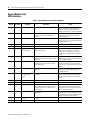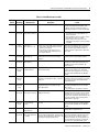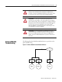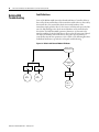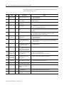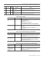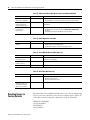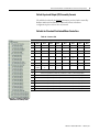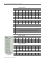
1
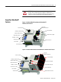
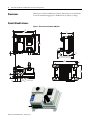
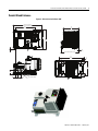
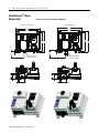
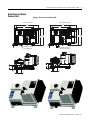
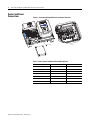
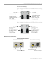
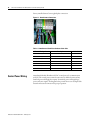
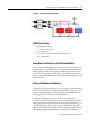
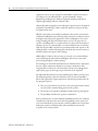
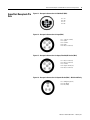
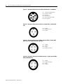
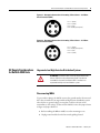
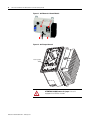
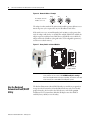
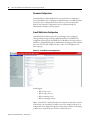
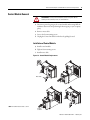
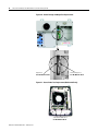
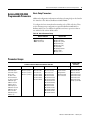
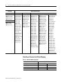
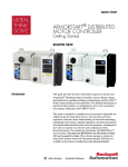
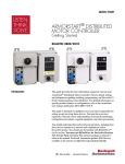
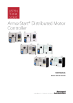
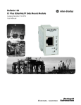
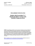
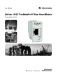
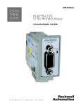
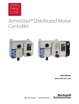
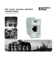
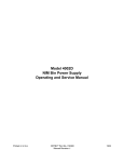
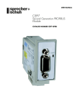
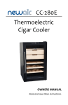
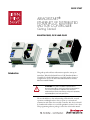
QUICK START
ARMORSTART®
ETHERNET/IP DISTRIBUTED
MOTOR CONTROLLER
Getting Started
BULLETIN 280E, 281E AND 284E
Introduction
This guide provides the basic information required to start up an
ArmorStart® EtherNet/Industrial Protocol (IP) Distributed Motor
Controller. For detailed information on specific product features or
configurations, refer to the ArmorStart EtherNet/IP user manual,
Publication 280E-UM001*.
ATTENTION: This guide is intended for qualified service
personnel responsible for setting up and servicing these devices.
The user must have previous experience with and a basic
understanding of electrical terminology, configuration procedures,
required equipment, and safety precautions.
The user should have a clear understanding of EtherNet/IP™ network
operations, including how slave devices operate on a network and
communicate with other devices and the controller. Also, the user should
be familiar with and have access to RSLogix 5000™ revision 17.01 or later.
This programming software package is referred to often in this manual.
2
ArmorStart EtherNet/IP Distributed Motor Controller Getting Started
General Precautions
In addition to the precautions listed throughout this manual, the following
statements, which are general to the system, must be read and understood.
ATTENTION: The controller contains ESD (electrostatic discharge)
sensitive parts and assemblies. Static control precautions are
required when installing, testing, servicing, or repairing the
assembly. Component damage may result if ESD control
procedures are not followed. If you are not familiar with static
control procedures, refer to Publication 8000-4.5.2, Guarding
against Electrostatic Discharge, or any other applicable ESD
protection handbooks.
ATTENTION: An incorrectly applied or installed controller can
damage components or reduce product life. Wiring or application
errors, such as undersizing the motor, incorrect or inadequate AC
supply, or excessive ambient temperatures, may result in
malfunction of the system.
ATTENTION: Only personnel familiar with the controller and
associated machinery should plan or implement the installation,
startup, and subsequent maintenance of the system. Failure to do
this may result in personal injury and/or equipment damage.
Precautions for Bulletin
280E/281E Applications
Precautions for Bulletin
284E Applications
Publication 280E-QS001B-EN-P – February 2011
ATTENTION: To prevent electrical shock, open disconnect switch
prior to connecting and disconnecting cables. Risk of shock –
environment rating may not be maintained with open receptacles.
ATTENTION: The drive contains high voltage capacitors which
take time to discharge after removal of mains supply. Before
working on drive, ensure isolation of mains supply from line inputs
(R, S, T [L1, L2, L3]). Wait three minutes for capacitors to discharge
to safe voltage levels. Failure to do so may result in personal injury
or death. Darkened display light-emitting diode (LED)s are not an
indication that capacitors have discharged to safe voltage levels.
Risk of shock – environment rating may not be maintained with
open receptacles.
ArmorStart EtherNet/IP Distributed Motor Controller Getting Started
3
ATTENTION: Only qualified personnel familiar with adjustable frequency
AC drives and associated machinery should plan or implement the
installation, startup, and subsequent maintenance of the system. Failure
to do this may result in personal injury and/or equipment damage.
ArmorStart EtherNet/IP
Features
Figure 1 – Bulletin 280E/281E ArmorStart with EtherNet/IP™
Communication Protocol
Local Disconnect
IP Address Notation Area
LED Status
Indication and Reset
Control Module
2 Outputs (Micro/M12)
4 Inputs (Micro/M12)
Hand-Off-Auto Keypad
IP Address Switches
Ethernet Ports (DLR)
Motor Connection
Base Module
Ground Terminal
Figure 2 – Bulletin 284E ArmorStart with EtherNet/IP™ Communication Protocol
Local Disconnect
LED Status
Indication and Reset
Control Module
IP Address Notation Area
2 Outputs (Micro/M12)
Hand-Off-Auto Keypad
4 Inputs (Micro/M12)
IP Address Switches
Ethernet Ports (DLR)
Source Brake Connection
Motor Connection
Base Module
Ground Terminal
Dynamic Brake Connection
Publication 280E-QS001B-EN-P – February 2011
4
ArmorStart EtherNet/IP Distributed Motor Controller Getting Started
Dimensions
Dimensions are shown in millimeters (inches). Dimensions are not intended to
be used for manufacturing purposes. All dimensions are subject to change.
Conduit Gland Entrance
Figure 3 – Dimensions for Bulletin 280E/281E
351
[13.82 ]
290
[11.42 ]
189
[7]
268
[10.55]
287,5
[11.32 ]
6,8
[.27 ]
150
[6 ]
3,02
[ .12 ]
MOTOR CONNECTION 185 [7.3] M22 CORDSET
MOTOR CONN ECTION 243 [9.57] M35 CORDSET
373
[14.69 ]
11
[ .43 ]
195
[7.68 ]
67,9
[3]
1" CONDUIT OPENING
39
[2]
47
[1.85 ]
0.75" CONDUIT OPENING
Publication 280E-QS001B-EN-P – February 2011
ArmorStart EtherNet/IP Distributed Motor Controller Getting Started
5
Conduit Gland Entrance
Figure 4 – Dimensions for Bulletin 284E
2HP or less 420.38 [16.55]
3HP or greater 444.38 [17.50]
290
[11.42]
236
[9]
268
[10.55]
287,5
[11.32 ]
3,02
[.12 ]
6,8
[.27 ]
MOTO R CONNECTION 266.9 [10.51]
373
[14.69]
11
[.43 ]
195
[7.68 ]
67,9
[3 ]
1" CONDUIT OPENING
39
[2 ]
47
[1.85 ]
0.75" CONDUIT OPENING
Publication 280E-QS001B-EN-P – February 2011
6
ArmorStart EtherNet/IP Distributed Motor Controller Getting Started
ArmorConnect® Gland
Connectivity
Figure 5 – Dimensions for Bulletin 280E/281E
3 Hp and less @ 480V AC
10 Hp @ 480V AC
351
[13.82]
290
[11.42]
351
[13.82]
290
[11.42]
268
[10.55 ]
268
287,5
[10.55] [11.32 ]
203.2
[8]
CABLE
KEEP OUT
6,8
[.27 ]
10 Amp Short Circuit
Protection (M22)
77,6
[3]
203.2
[8]
CABLE
KEEP OUT
6,8
[.27 ]
25 Amp Short Circuit
Protection (M35)
77,6
[3 ]
60,6
[2 ]
25,5
[1 ]
60,6
[2 ]
68
[2.68 ]
Publication 280E-QS001B-EN-P – February 2011
25,5
[1 ]
68
[2.68 ]
287,5
[11.32]
ArmorStart EtherNet/IP Distributed Motor Controller Getting Started
ArmorConnect Gland
Connectivity
Figure 6 – Dimensions for Bulletin 284E
2 Hp or less at 480V
290
[11.42]
3 Hp or greater at 480V
419,53
[16.52]
290
[11.42]
444,38
[17.50]
30,4
[1 ]
268
[10.55]
287,5
268
[10.55] [11.32]
6,8
[.27 ]
7
6,8
[.27 ]
10 Amp Short Circuit
Protection (M22)
287,5
[11.32 ]
25 Amp Short Circuit
Protection (M35)
77,6
[3 ]
77,6
[3]
60,6
[2 ]
60,6
[2]
25,5
[1]
68
[2.68 ]
25,5
[1 ]
68
[2.68 ]
Publication 280E-QS001B-EN-P – February 2011
8
ArmorStart EtherNet/IP Distributed Motor Controller Getting Started
Control and Power
Connections
Figure 7 – ArmorStart EtherNet/IP Power and Control Terminals
Detail A
See Detail A
Table 1 - Power, Control and Ground Terminal Designations
Publication 280E-QS001B-EN-P – February 2011
Terminal Designations
No. of Poles
Description
A1 (+)
2
Control Power Input
A2 (–)
2
Control Power Common
A3 (+)
2
Unswitched 24V Control
PE
2
Ground
1/L1
2
Line Power Phase A
3/L3
2
Line Power Phase B
5/L5
2
Line Power Phase C
ArmorStart EtherNet/IP Distributed Motor Controller Getting Started
9
Recommended Cord Grips
Figure 8 – Cord grips for ArmorStart Devices with 10 A Short Circuit Protection Rating
3/4 in. Lock Nut
1 in. Lock Nut
Thomas & Betts Cord Grip
Cat. No. 2931NM
3/4 in. Stain Relief Cord Connector
Cable Range: 0.31…0.56 in.
Used with Control Power Media
Cordset - Example:
Thomas & Betts Cord Grip
Cat. No. 2940NM
1 in. Stain Relief Cord Connector
Cable Range: 0.31…0.56 in.
Used with Three-Phase Power
Media Cordset - Example:
Cat. No. 889N-M65GF-M2
Cat. No. 280-PWR22G-M1
Figure 9 – Cord grips for ArmorStart Devices with 25 A Short Circuit Protection Rating
3/4 in. Lock Nut
1 in. Lock Nut
Thomas & Betts Cord Grip
Cat. No. 2931NM
3/4 in. Stain Relief Cord Connector
Cable Range: 0.31…0.56 in.
Used with Control Power Media
Cordset - Example:
Thomas & Betts Cord Grip
Cat. No. 2942NM
1 in. Stain Relief Cord Connector
Cable Range: 0.70…0.95 in.
Used with Three-Phase Power
Media Cordset - Example:
Cat. No. 889N-M65GF-M2
Cat. No. 280-PWR35G-M1
ArmorConnect Connections
Figure 10 – ArmorConnect Receptacles
10 A Short Circuit Protection Rating
Control Power Receptacle
Three-Phase Power Receptacle
25 A Short Circuit Protection Rating
Control Power Receptacle
Three-Phase Power Receptacle
Publication 280E-QS001B-EN-P – February 2011
10
ArmorStart EtherNet/IP Distributed Motor Controller Getting Started
Factory installed ArmorConnect gland plate connections
Figure 11 – ArmorConnect Connections
Table 2 - ArmorConnect Gland Plate Conductor Color Code
Control Power Wiring
Publication 280E-QS001B-EN-P – February 2011
Terminal Designations
Description
Color Code
A1 (+)
Control Power Input
Blue
A2 (–)
Control Power Common
Black
A3 (+)
Unswitched Control Power
Red
PE
Ground
Green/Yellow
1/L1
Line Power – Phase A
Black
2/L2
Line Power – Phase B
White
3/L3
Line Power – Phase C
Red
ArmorStart EtherNet/IP utilizes 24V DC control power for communications
and I/O. The control power terminal connections are labeled A1,A2, and A3.
Switched power will supply the outputs. Unswitched power will supply logic
power and sensor inputs. The diagram below provides the user an example of the
internal and external connections for proper operation.
ArmorStart EtherNet/IP Distributed Motor Controller Getting Started
11
Figure 12 – Control Power Wiring Example
24V DC Control Power
• Rated Operation Voltage
– 24V DC (–15%, +10%)
• A1 = Switched +V
• A2 = Common for both switched and unswitched (–V)
• A3 = Unswitched +V
Group Motor Installations for USA and Canada Markets
The ArmorStart Distributed Motor controllers are listed for use with each other
in group installations per NFPA 79, Electrical Standard for Industrial Machinery.
When applied according to the group motor installation requirements, two or
more motors, of any rating or controller type, are permitted on a single branch
circuit. Group Motor Installation has been successfully used for many years in the
USA and Canada.
Wiring and Workmanship Guidelines
In addition to conduit and seal-tite raceway, it is acceptable to utilize cable that is
dual rated Tray Cable, Type TC-ER and Cord, STOOW, for power and control
wiring on ArmorStart installations. In the USA and Canada installations, the
following guidance is outlined by the NEC and NFPA 79.
In industrial establishments where the conditions of maintenance and
supervision ensure that only qualified persons service the installation, and where
the exposed cable is continuously supported and protected against physical
damage using mechanical protection, such as struts, angles, or channels, Type TC
tray cable that complies with the crush and impact requirements of Type MC
(Metal Clad) cable and is identified for such use with the marking Type TC-ER
(Exposed Run)* shall be permitted between a cable tray and the utilization
Publication 280E-QS001B-EN-P – February 2011
12
ArmorStart EtherNet/IP Distributed Motor Controller Getting Started
equipment or device as open wiring. The cable shall be secured at intervals not
exceeding 1.8 m (6 ft) and installed in a “good workman-like” manner.
Equipment grounding for the utilization equipment shall be provided by an
equipment grounding conductor within the cable.
*Historically cable meeting these crush and impact requirements were designated
and marked “Open Wiring”. Cable so marked is equivalent to the present Type
TC-ER and can be used.
While the ArmorStart is intended for installation in factory floor environments
of industrial establishments, the following must be taken into consideration when
locating the ArmorStart in the application: Cables, including those for control
voltage including 24V DC and communications, are not to be exposed to an
operator or building traffic on a continuous basis. Location of the ArmorStart to
minimize exposure to continual traffic is recommended. If location to minimize
traffic flow is unavoidable, other barriers to minimize inadvertent exposure to the
cabling should be considered. Routing cables should be done in such a manner to
minimize inadvertent exposure and/or damage.
Additionally, if conduit or other raceways are not used, it is recommended that
strain relief fittings be utilized when installing the cables for the control and
power wiring through the conduit openings.
The working space around the ArmorStart may be minimized as the ArmorStart
does not require examination, adjustment, servicing or maintenance while
energized. In lieu of this service, the ArmorStart is meant to be unplugged and
replaced after proper lockout/tag-out procedures have been employed.
The Hand-Off-Auto (HOA) is a factory installed option that the user may select.
The HOA keypad may require the ArmorStart to be selected and installed as
follows if the application requires frequent use of the hand operated interface by
the equipment operator:
1. They are not less than 0.6 m (2 ft) above the servicing level and are within
easy reach of the normal working position of the operator.
2. The operator is not placed in a hazardous situation when operating them.
3. The possibility of inadvertent operation is minimized.
If the operated interface is used in industrial establishments where the conditions
of maintenance and supervision ensure that only qualified persons operate and
service the ArmorStart's operator interface, and the installation is located so that
inadvertent operation is minimized then other installation locations with
acceptable access can be provided.
Publication 280E-QS001B-EN-P – February 2011
ArmorStart EtherNet/IP Distributed Motor Controller Getting Started
ArmorStart Receptacle Pin
Outs
13
Figure 13 – Receptacle Connections for EtherNet/IP (M12)
Pin 1: Tx+
Pin 2: Rx+
Pin 3: Tx–
Pin 4: Rx–
Figure 14 – Receptacle Connections for Input (M12)
Pin 1: +24V (A3 or DNET)
Pin 2: Input 0
Pin 3: Common
Pin 4: Input 1
Pin 5: NC (no connection)
Figure 15 – Receptacle Connections for Output, EtherNet/IP Version (M12)
Pin 1: NC (no connection)
Pin 2: NC (no connection)
Pin 3: Common
Pin 4: Output +24V DC (A1)
Pin 5: NC (no connection)
Figure 16 – Receptacle Connections for Dynamic Brake (M22) – Bulletin 284E only
Pin 1: GND (green/yellow)
Pin 2: BR+ (black)
Pin 3: BR- (white)
Publication 280E-QS001B-EN-P – February 2011
14
ArmorStart EtherNet/IP Distributed Motor Controller Getting Started
Figure 17 – Receptacle Connections for Incoming Control Power – 24V DC Only
Pin 1: +24V DC unswitched (A3) (red)
Pin 2: Common (A2) (black)
Pin 3: PE (green)
Pin 4: Not used (blank)
Pin 5: +24V DC switched (A1) (blue)
Pin 6: Not used (white)
Figure 18 – Receptacle Connections for Source or Control Brake – Bulletin 284E
only
Pin 1: L1 (black)
Pin 2: GND (green/yellow)
Pin 3: L2 (white)
Figure 19 – Receptacle Connections for Motor Connector (M22) – Bulletin 280E/
281E: 3 Hp or less and Bulletin 284E: 5 Hp or less
Pin 1: T1 (black)
Pin 2: T2 (white)
Pin 3: T3 (red)
Pin 4: Ground (green/yellow)
Figure 20 – Receptacle Connections for Motor Connector – 10 Hp or greater (M35) –
Bulletin 280E/281E only
Pin 1: T1 (black)
Pin 2: Ground (green/yellow)
Pin 3: T3 (red)
Pin 4: T2 (white)
Publication 280E-QS001B-EN-P – February 2011
ArmorStart EtherNet/IP Distributed Motor Controller Getting Started
15
Figure 21 – Receptacle Connections for Incoming 3-Phase Power – 10 A Short
Circuit Protection (M22)
Pin 1: L1 (black)
Pin 2: L2 (white)
Pin 3: L3 (red)
Pin 4: Ground (green/yellow)
Figure 22 – Receptacle Connections for Incoming 3-Phase Power – 25 A Short
Circuit Protection (M35)
Pin 1: L1 (black)
Pin 2: Ground (green/yellow)
Pin 3: L3 (red)
Pin 4: L2 (white)
AC Supply Considerations
for Bulletin 284E Units
Ungrounded and High Resistive Distribution Systems
ATTENTION: The Bulletin 284E contains protective Metal Oxide
Varistors (MOV)s that are referenced to ground. These devices
should be disconnected if the Bulletin 284E is installed on an
ungrounded and high resistive distribution system.
Disconnecting MOVs
To prevent drive damage, the MOVs connected to ground must be disconnected
if the drive is installed on an ungrounded and high resistive distribution system
where the line-to-ground voltages on any phase could exceed 125% of the
nominal line-to-line voltage. To disconnect the MOVs, remove the jumper shown
in Figure 24, Jumper Removal.
1. Before installing the Bulletin 284E, loosen four mounting screws.
2. Unplug control module from the base unit by pulling forward.
Publication 280E-QS001B-EN-P – February 2011
16
ArmorStart EtherNet/IP Distributed Motor Controller Getting Started
Figure 23 – 284E Removal of Control Module
Figure 24 – 284E Jumper Removal
Remove Jumper
ATTENTION: DO NOT remove this jumper if the unit is
equipped with an EMI filter installed.
Publication 280E-QS001B-EN-P – February 2011
ArmorStart EtherNet/IP Distributed Motor Controller Getting Started
Configuring EtherNet/IP
Address
17
Before using the ArmorStart you may need to configure an IP address, subnet
mask, and optional Gateway address. The rotary network address switches found
on the I/O section of the ArmorStart are set to 999 and DHCP is enabled as the
factory default. The ArmorStart reads these switches first to determine if the
switches are set to a valid IP address between 1…254. When switches are set to a
valid number the IP address will be 192.168.1._ _ _ [switch setting].
The IP address can also be set using DHCP or BootP.
• If BootP is preferred, use Rockwell Automation BootP utility, version 2.3
or later, that ships with RSLogix™ 5000 or RSLinx® software.
• If DHCP is preferred, use a third party DHCP server.
This document assumes the user has set the IP address to 192.168.1.1. The user
can change this IP address to any address either statically or dynamically.
ATTENTION: To avoid unintended operation, the adapter must be
assigned a fixed IP address. If a DHCP server is used, it must be
configured to assign a fixed IP address for your adapter.
Failure to observe this precaution may result in unintended
machine motion or loss of process control.
Manually Configure the Network Address Switches
Remove the protective caps from the rotary switches. Set the network address by
adjusting the three switches on the front of the I/O module.
Figure 25 – Switches on the I/O Module
Writable surface for IP address
Protective IP67 Caps
Publication 280E-QS001B-EN-P – February 2011
18
ArmorStart EtherNet/IP Distributed Motor Controller Getting Started
Figure 26 – Network Address Example
X10
X100
This example shows the
IP address set to 163.
2
8
6
X1
0
0
4
0
2
8
6
4
2
8
6
4
The adapter’s subnet mask will be 255.255.255.0 and the gateway address is set to
0.0.0.0. A power cycle is required for any new IP address to take effect.
If the switches are set to an invalid number (such as 000 or a value greater than
254), the adapter will check to see if DHCP is enabled. If DHCP is enabled, the
adapter requests an address from a DHCP server. If DHCP is not enabled, the
adapter will use the IP address (along with other TCP configurable parameters)
stored in non-volatile memory.
Figure 27 – Rotary Switch on Control Module
Factory Setting 99
DO NOT CHANGE
IMPORTANT
Use the Rockwell
Automation BootP/DHCP
Utility
Publication 280E-QS001B-EN-P – February 2011
Refer to Figure 27, the ArmorStart is shipped with the control module
rotary switches set to a value of 99. DO NOT modify this setting. If
these are changed and the unit stops responding, the switches will need
to be manually set to node address 63 and power cycled.
The Rockwell Automation BootP/DHCP utility is a stand alone program that
incorporates the functionality of standard BootP software with a user friendly
graphical interface. It is located in the Utils directory on the RSLogix5000
installation CD. The ArmorStart EtherNet/IP adapter must have DHCP
enabled (factory default) to use the utility.
ArmorStart EtherNet/IP Distributed Motor Controller Getting Started
DHCP IP Support
19
DHCP (Dynamic Host Configuration Protocol) software automatically assigns
IP addresses to client stations logging onto a TCP/IP network.
When DHCP is enabled (factory default Enabled), the unit will request its
network configuration from a DHCP/BOOTP server. Any configuration
received from a DHCP server will be stored in non-volatile memory.
ArmorStart EtherNet/IP will remember the last successful address if DHCP is
enabled. The possibility exists that the adapter will be assigned a different IP
address, which would cause the adapter to cease communicating with the
ControlLogix® controller.
Internal Web Server
Using the Rockwell
Automation Embedded Web
ArmorStart Ethernet/IP internal web server allows you to view information and
Server
configure the ArmorStart via a web browser. The embedded web server is used to
access configuration and status data. Security in the form of an administrative
password can be set. The default Login is Administrator. There is no password
set by default.
IMPORTANT
Caution: The user should set the password to a unique value for
authorized personnel. If the Login and password are lost you will need
to reset the device to factory defaults losing its configuration.
To access the internal web browser, open your computers internet browser and
enter the IP address of the desired ArmorStart (192.168.1.1).
Figure 28 – Internal Web Browser
Publication 280E-QS001B-EN-P – February 2011
20
ArmorStart EtherNet/IP Distributed Motor Controller Getting Started
Parameter Configuration
ArmorStart Ethernet/IP embedded web server provides the user the ability to
view and modify the device configuration without having to access RSLogix 5000.
To view the device configuration from the web server, select the Parameters
folder. For the parameter configuration, the user will login through the
Administrative Settings or when prompted.
E-mail Notification Configuration
ArmorStart Ethernet/IP internal web server will support the e-mailing of
warning and trip messages via Simple Mail Transfer Protocol (SMTP). The
configuration parameters for the SMTP Server’s IP address, user login, and port
number are configurable through the Administrative Settings page of the internal
web server. The user will configure the device name, device description, and
device trip type.
Figure 29 – E-mail Notification Configuration
E-mail triggers:
– When a trip occurs.
– When a trip is cleared.
– When a warning occurs.
– When a warning is cleared.
Note: “Cleared Event” e-mails will only be sent when all events have been cleared
and if an trip event e-mail has previously been sent. For example, if the device is
configured to send e-mails when a phase loss trip is detected and an overload trip
is detected, no e-mail will be sent when the overload is cleared.
Publication 280E-QS001B-EN-P – February 2011
ArmorStart EtherNet/IP Distributed Motor Controller Getting Started
ArmorStart EtherNet/IP
Add-On Profile for Logix
21
The Add-On Profile (AOP) must be installed in order for RSLogix 5000 to fully
support the ArmorStart EtherNet/IP product. The AOP can be downloaded
from http://www.rockwellautomation.com/support/downloads.html.
Example - Adding ArmorStart to RSLogix 5000
1. In the RSLogix 5000 tree select the Ethernet® adapter and add a new
module.
Note: The ArmorStart EtherNet/IP AOP must be installed prior to this
step.
Figure 30 – Controller Organizer
Publication 280E-QS001B-EN-P – February 2011
22
ArmorStart EtherNet/IP Distributed Motor Controller Getting Started
2. Within the “Other” category select the ArmorStart.
Figure 31 – Select Module Box
3. Configure the new module by adding a name and the IP address.
Figure 32 – New Module Box
Publication 280E-QS001B-EN-P – February 2011
ArmorStart EtherNet/IP Distributed Motor Controller Getting Started
23
4. Go online with the controller via RSWho and download the project to the
processor.
Figure 33 – RSWho Box
5. Open the controller tags to view the units command, status, and diagnostic
information.
Figure 34 – Controller Tags
Publication 280E-QS001B-EN-P – February 2011
24
ArmorStart EtherNet/IP Distributed Motor Controller Getting Started
Diagnostics
EtherNet/IP LED Status
Indication
Figure 35 – EtherNet/IP LED
EtherNet/IP LED status and diagnostics consists of four LEDs.
• Link Activity/Status LEDS
– Ethernet Link1 Activity/Status (Port 1) – LED Color: Bicolor
(Green/Yellow), refer to Table 3
– Ethernet Link2 Activity/Status (Port 2) – LED Color: Bicolor
(Green/Yellow), refer to Table 3
• “MOD” LED – Bicolor Red/Green represents the Ethernet Module
status, refer to Table 4
• “NET” LED – Bicolor Red/Green represents the Ethernet Network
status, refer to Table 6
Table 3 - Link 1 or Link 2 Port Activity/Status
Link 1 or 2 Status LED
Description
Recommended Action
Off
No link established
Verify network cabling, and correct, as needed.
Green
Link established at 100 Mbps
None
Flashing green
Transmit or receive activity present at 100 Mbps
None
Yellow
Link established at 10 Mbps
None
Flashing yellow
Transmit or receive activity present at 10 Mbps
None
Table 4 - Module Status Indicator
MOD Status LED
Summary
Requirement
Steady Off
No power
If no power is supplied to the device, the module status indicator shall be
steady off.
Steady Green
Device operational
If the device is operating correctly, the module status indicator shall be
steady green.
Flashing Green
Standby
If the device has not been configured, the module status indicator shall
be flashing green.
Flashing Red
Minor fault
If the device has detected a recoverable minor fault, the module status
indicator shall be flashing red.
Note: An incorrect or inconsistent configuration would be considered a
minor fault.
Steady Red
Major fault
If the device has detected a non-recoverable major fault, the module
status indicator shall be steady red, refer to Table 5.
Flashing Green/Red
Self-test
While the device is performing its power up testing, the module status
indicator shall be flashing green/red.
Publication 280E-QS001B-EN-P – February 2011
ArmorStart EtherNet/IP Distributed Motor Controller Getting Started
25
Refer to Parameter 63 "Base Trip" for the Base Module Trip Status.
Table 5 - "Steady Red" MOD LED Status (Refer to Table 4 above.)
Fault Type
Description
0
EEPROM Fault
Non-volatile memory value out of range for a local parameter, or a write failure detected. This fault
is also reflected by a solid red MOD status LED.
1
Internal Comm2
The Internal communication connection has timed out. This fault is also reflected by a flashing red
MOD status LED.
2
Hardware Fault
Internal diagnostics checks failed. This fault is also reflected by a solid red MOD status LED.
3
Control Module
An illegal or unsupported Control Module product code or revision has been detected. Also reported
if no Control Module is detected on power up. This fault is also reflected by a solid red MOD status
LED.
Reserved
Reserved
4…15
Table 6 - Network LED Status Indication
NET Status LED
Description
Recommended Action
Flashes
Green-Red-Off
The device has not completed the initialization, is
Check to make sure the product is properly wired
not on an active network, or may not be powered up. and configured on the network.
Solid Green
The device is operating in a normal condition.
No action required.
Flashing Green
The device is operating in a normal condition.
No action required.
Flashing Red
Internal network fault has occurred.
Check 3-phase and control power connections.
Check ethernet connections.
Solid Red
The device has detected a major error that has
rendered it incapable of working.
Troubleshooting should be done to ensure that
the control module internal switch settings are
correct. Consult factory.
Control Module LED
Status and Reset
Figure 36 – LED Status
Indication and Reset
The Control Module LED status and diagnostics consists of four status LEDs
and a Reset button. The following is a brief explanation of the operation of each
LED found on the Control Module.
Table 7 - Control Module LED Status Indication
LED
Definition
Recommended Action
Power
This LED will be illuminated solid green
when switched control power is present
and with the proper polarity.
Ensure 24V DC is present on A1 and A2.
Check if the local disconnect is in the OFF
position.
Run
This LED will be illuminated solid green
when a start command and control power
is present.
Ensure 24V DC is present on A1 and A3.
Check if the user is properly commanding to
RUN via Instance 162 or 166.
Network
This bicolor LED is used to indicate the
status of the internal network connection.
See Table 6, Network LED Status Indication
table above for additional information.
Fault
This LED is used to indicate the fault
status of the ArmorStart. When the unit is
faulted, the unit will respond with a
specific blink pattern to identify the fault.
See Table 8 and Table 9 below for
additional information.
The “Reset Button” is a local trip reset.
Publication 280E-QS001B-EN-P – February 2011
26
ArmorStart EtherNet/IP Distributed Motor Controller Getting Started
Control Module Fault
LED Indications
Table 8 - Fault LED Indicators for Bulletin 280E/281E
Blink
Pattern
AutoResettable
Bulletin 280E/281E
Trip Status
1
No
Short Circuit
The circuit breaker (140M) has tripped.
Determine cause of trip. Try to reset the circuit
breaker using the disconnect handle. If the
conditions continue, check power wiring or
replace based module. This cannot be disabled.
2
Yes
Overload
The load has drawn excessive current and based
on the trip class selected, the device has
tripped.
Verify that the load is operating correctly and
the ArmorStart is properly set-up. the fault
cannot be disabled.
3
Yes
Phase Loss
The ArmorStart has detected a missing phase.
Verify that 3-phase voltage is present at the line
side connections. This fault can be disabled and
is disabled by default.
4
—
Reserved
Not Used
—
5
—
Reserved
Not Used
—
6
Yes
Control Pwr Loss
(Switched Power)
The ArmorStart has detected a loss of the
control power voltage.
Check control voltage, wiring, and proper
polarity (A1/A2 terminal). Also, check and
replace the control voltage fuse, if necessary.
This fault can be disabled and is disabled by
default.
7
Yes
Input Fault
This error indicates a shorted sensor, shorted
input device, wiring input mistakes, or a blown
output fuse.
Correct, isolated or remove wiring error prior to
restarting the system. This fault can be disabled
and is disabled by default.
8
Yes
Over Temperature
This fault is generated when the operating
temperature has been exceeded. This fault
cannot be disabled.
Check for blocked or dirty heat sink fins. Verify
that ambient temperature has not exceeded
40°C (104°F). 1. Clear the fault or cycle power to
the drive.
9
Yes
Phase Imbalance
The ArmorStart has detected a voltage
imbalance.
Check the power system and correct if
necessary. This fault can be disabled and is
disabled by default.
10
Yes
Control Power (24V DC)
Lost (Unswitched
Power)
The 24V DC power supply is below tolerance
threshold.
Check the state of the network power supply
(A3/A1 terminal) and look for media problems.
This fault can be disabled and is disabled by
default.
11
—
Reserved
Not Used
—
12
—
Reserved
Not Used
—
13
No
EEprom
This is a major fault, which renders the
ArmorStart inoperable. Possible causes of this
fault are transients induced during EEprom
storage routines.
If the fault was initiated by a transient, power
cycling should clear the problem, otherwise
replacement of the ArmorStart may be required.
This fault cannot be disabled.
14
No
Hdw Flt
This fault indicates that a serious hardware
problem exists.
Check for a base/starter module mismatch. If no
mismatch exists, the ArmorStart may need to be
replaced. (Hdw Flt is the factory-enabled default
setting.) This fault cannot be disabled.
15
—
Reserved
Not Used
—
16
—
Reserved
Not Used
—
Publication 280E-QS001B-EN-P – February 2011
Description
Action
ArmorStart EtherNet/IP Distributed Motor Controller Getting Started
27
Table 9 - Fault LED Indicators for 284E
Bit/Blink
Pattern
AutoResettable
1
No
2
284E Trip Status
Description
Action
Short Circuit
The circuit breaker (140M) has tripped.
Determine cause of trip. Try to reset the circuit
breaker using the disconnect handle. If the
conditions continue, check power wiring or
replace based module. This cannot be disabled.
Drive
Controlled
Overload
(Drive Codes 7 and 64)
An excessive motor load exists
1. Reduce load so drive output current does not
exceed the current set by Parameter 133
(Motor OL Current).
2. Verify Parameter 184 (Boost Select) setting.
3. Drive rating of 150% for 1 minute.
4. Reduce load or extend Accel Time two
hundred percent or when 3 seconds has been
exceeded.
3
Drive
Controlled
Phase Short
(Drive Codes 38…43)
1. Phase U, V, or W to Gnd. A phase to ground
fault has been detected between the drive
and motor in this phase.
2. Phase UV, UW, or VW Short. Excessive
current has been detected between these
two output terminals.
Check the wiring between the drive and motor.
Check motor for grounded phase. Check the
motor and drive output terminal wiring for a
shorted condition. Replace drive if fault cannot
be cleared.
4
Drive
Controlled
Ground Fault
(Drive Code 13)
A current path to earth ground has been
detected at one or more of the drive output
terminals.
Check the motor and external wiring to the drive
output terminals for a grounded condition.
5
Drive
Controlled
Stall
(Drive Code 6)
Drive is unable to accelerate motor.
Increase Parameters 139…167 (Accel Time x) or
reduce load so drive output current does not
exceed the current set by Parameter 189
(Current Limit 1).
6
Parameter 23
(PrFlt Reset
Mode)
Control Pwr Loss
(Switched Power)
The ArmorStart has detected a loss of the
control power voltage.
Check control voltage, wiring, and proper
polarity (A1/A2 terminal). Also, check and
replace the control voltage fuse, if necessary.
This fault can be disabled and is disabled by
default.
7
Parameter 23
(PrFlt Reset
Mode)
Input Fault
This error indicates a shorted sensor, shorted
input device, wiring input mistakes, or a blown
output fuse.
If this fault occurs, the offending problem
should be isolated or removed prior to restarting
the system. This fault can be disabled and is
disabled by default.
8
Parameter 23
(PrFlt Reset
Mode)
Over Temperature
This fault is generated when the operating
temperature has been exceeded. This fault
cannot be disabled.
Check for blocked or dirty heat sink fins. Verify
that ambient temperature has not exceeded
40°C (104°F).
1. Clear the fault or cycle power to the drive.
9
Drive
Controlled
Over Current
(Drive Codes 12 and 63)
The drive output current has exceeded the
hardware current limit.
Check programming. Check for excess load,
improper Parameter 184 (Boost Select) setting.
DC brake volts set too high or other causes of
excess current. Parameter 198 (SW Current Trip)
has been exceeded, check load requirements
and Parameter 198 setting.
10
Parameter 23
(PrFlt Reset
Mode)
Control Power (24V DC)
Lost (Unswitched
Power)
The 24V DC power supply is below tolerance
threshold.
Check the state of the network power supply
(A3/A1 terminal) and look for media problems.
This fault can be disabled and is disabled by
default.
11
No
Internal Comm
(Drive Code 81)
RS485 (DSI) port stopped communicating.
Clear the fault or cycle power to the drive. If the
problem persists replace the unit.
12
Drive
Controlled
DC Bus Fault
(Drive Codes Reference
3, 4 and 5)
Power Loss - DC bus voltage remained below
85% of nominal. UnderVoltage - DC but voltage
fell below the minimum value. OverVoltage - DC
bus voltage exceeded maximum value.
Monitor the incoming AC line for low voltage or
line power interruption. Check the input fuses.
Monitor the AC line for high line voltage or
transient conditions. Bus overvoltage can also
be caused by motor regeneration. Extend the
decel time or install dynamic brake option.
Publication 280E-QS001B-EN-P – February 2011
28
ArmorStart EtherNet/IP Distributed Motor Controller Getting Started
Table 9 - Fault LED Indicators for 284E
Bit/Blink
Pattern
AutoResettable
13
No
EEprom
(PF Drive Code
Reference 100)
The checksum read from the board does not
match the checksum calculated.
Set Parameter 141 (Reset to Defaults) to
Option 1 “Reset Defaults”.
14
No
Hdw Flt (PF Drive Codes
Reference 70 and 122)
Failure has been detected in the drive power
section or drive control and I/O section.
1. Cycle power.
2. Replace drive if fault cannot be cleared.
15
Drive
Controlled
Restart Retries (PF
Drive Code Reference
33)
Drive unsuccessfully attempted to reset a fault
and resume running for the programmed number
of Parameter 192 (Auto Rstrt Tries).
Correct the cause of the fault and manually
clear.
16
Drive
Controlled
Misc. Fault (PF Drive
Code Reference 2, 8,
29, 48 and 80)
Heatsink temperature exceeds a predefined
value. The drive was commanded to write
default values to EEprom. The autotune function
was either cancelled by the user or failed.
Check for blocked or dirty heat sink fins. Verify
that ambient temperature has not exceeded
40°C (104°F).
1. Clear the fault or cycle power to the drive.
2. Program the drive parameters as needed.
Restart procedure.
284E Trip Status
Troubleshooting
Description
Action
Introduction
The purpose of this section is to assist in troubleshooting the ArmorStart®
Distributed Motor Controller using the LED Status Display and diagnostic
parameters.
ATTENTION: Servicing energized industrial control equipment can be
hazardous. Electrical shock, burns or unintentional actuation of controlled
industrial equipment may cause death or serious injury. For safety of
maintenance personnel as well as others who might be exposed to
electrical hazards associated with maintenance activities, follow the local
safety related work practices (for example, the NFPA70E, Part II in the
United States). Maintenance personnel must be trained in the safety
practices, procedures, and requirements that pertain to their respective
job assignments.
ATTENTION: Do not attempt to defeat or override fault circuits. The
cause of the fault indication must be determined and corrected before
attempting operation. Failure to correct a control system of mechanical
malfunction may result in personal injury and /or equipment damage due
to uncontrolled machine system operation.
ATTENTION: The drive contains high voltage capacitors that take time to
discharge after removal of mains supply. Before working on drive, ensure
isolation of mains supply from line inputs (R, S, T, [L1, L2, L3]). Wait three
minutes for capacitors to discharge to safe voltage levels. Failure to do so
may result in personal injury or death.
Darkened display LEDs is not an indication that capacitors have
discharged to safe voltage levels.
Publication 280E-QS001B-EN-P – February 2011
ArmorStart EtherNet/IP Distributed Motor Controller Getting Started
29
ATTENTION: Only qualified personnel familiar with adjustable frequency
AC drives and associated machinery should plan or implement the
installation, startup, and subsequent maintenance of the system. Failure
to comply may result in personal injury and/or equipment damage.
ATTENTION: This drive contains electrostatic discharge (ESD) –
sensitive parts and assemblies. Static control precautions are required
when installing, testing, servicing, or repairing this assembly. Component
damage may result if ESD control procedures are not followed. If you are
not familiar with static control procedures, refer to Allen-Bradley®
Publication 8000-4.5.2, Guarding against Electrostatic Damage, or any
other applicable ESD protection handbook.
ATTENTION: An incorrectly applied or installed drive can result in
component damage or a reduction in product life. Wiring or application
errors, such as undersizing of the motor, incorrect or inadequate AC
supply, or excessive ambient temperatures may result in malfunction of
the system.
Bulletin 280E/281E
Troubleshooting
The following flowchart for Bulletin 280E/281E units, is provided to aid in
quick troubleshooting.
Figure 37 - Bulletin 280E/281E Control Module LED Status
Yes
Faulted Display
No
Fault
LED
Network
LED
Motor will
not Start
See
Table 8
See
Table 6
See
Table 10
Publication 280E-QS001B-EN-P – February 2011
30
ArmorStart EtherNet/IP Distributed Motor Controller Getting Started
Bulletin 284E
Troubleshooting
Fault Definitions
Some of the Bulletin 284E ArmorStart Distributed Motor Controller faults are
detected by the internal hardware of the ArmorStart, while others are detected by
the internal drive. For internal drive faults, the internal hardware of the
ArmorStart simply polls the drive for the existence of faults and reports the fault
state. No fault latching is done by the internal hardware of the ArmorStart for
these faults. The PrFlt ResetMode parameter (Parameter 23) determines the
Auto Resettability of only the faults that are detected on the main control board.
The Auto Resettability of the faults that are detected in the internal drive is
controlled by internal drive parameters, refer to Table 9. The following flowchart
for Bulletin 284E units, is provided to aid in quick troubleshooting.
Figure 38 - Bulletin 284E Control Module LED Status
Faulted Display
Yes
No
Fault
LED
Network
LED
Define Nature
of the
Problem
Motor will
not start
See
Table 9
See
Table 6
See
Table 12
Actions
Publication 280E-QS001B-EN-P – February 2011
ArmorStart EtherNet/IP Distributed Motor Controller Getting Started
31
Internal Drive Faults
A fault is a condition that stops the drive. There are two fault types.
Type
Description
1
Auto-Reset/Run
When this type of fault occurs, Parameter 192 (Auto Rstrt Tries) and related
Parameter(s): 155, 193 are set to a value greater than 0, a user-configurable timer,
Parameter 193 (Auto Rstrt Delay) and related Parameter(s): 192, begins. When the
timer reaches zero, the drive attempts to automatically reset the fault. If the
condition that caused the fault is no longer present, the fault will be reset and the
drive will be restarted
2
Non-Resettable
This type of fault may require drive or motor repair, or is caused by wiring or
programing errors. The cause of the fault must be corrected before the fault can be
cleared.
Automatically Clearing Faults (Option/Step)
Clear a Type 1 Fault and Restart the Drive:
1. Set Parameter 192 (Auto Rstrt Tries) to a value other than 0.
2. Set Parameter 193 (Auto Rstrt Delay) to a value other than 0.
Clear an Overvoltage, Undervoltage or Heatsink OvrTmp Fault without
Restarting the Drive:
1. Set Parameter 192 (Auto Rstrt Tries) to a value other than 0.
2. Set Parameter 193 (Auto Rstrt Delay) to 0.
Auto Restart (Reset/Run)
The Auto Restart feature provides the ability for the drive to automatically
perform a fault reset followed by a start attempt without user or application
intervention. This allows remote or unattended operation. Only certain faults are
allowed to be reset. Certain faults (Type 2) that indicate possible drive
component malfunction are not resettable. Caution should be used when
enabling this feature, since the drive will attempt to issue its own start command
based on user selected programming.
Publication 280E-QS001B-EN-P – February 2011
32
ArmorStart EtherNet/IP Distributed Motor Controller Getting Started
The following table describes Bulletin 284E Faults as seen in Parameters 107,
108, and 109 (Fault 1, 2 or 3).
No.
Fault
Type
➊
F2
Auxiliary Input
1
Auxiliary input interlock is open.
1. Check remote wiring.
2. Verify communications.
F3
Power Loss
2
DC bus voltage remained below
85% of nominal.
3. Monitor the incoming AC line for low voltage or line power interruption.
4. Check input fuses.
F4
UnderVoltage
1
DC bus voltage fell below the
minimum value.
5. Monitor the incoming AC line for low voltage or line power interruption.
F5
OverVoltage
1
DC bus voltage exceeded
maximum value.
6. Monitor the AC line for high line voltage or transient conditions. Bus
overvoltage can also be caused by motor regeneration. Extend the decel
time or install dynamic brake option.
F6
Motor Stalled
1
Drive is unable to accelerate
motor.
7. Increase Parameters 139…167 (Accel Time x) or reduce load so drive
output current does not exceed the current set by Parameter 189 (Current
Limit 1).
F7
Motor Overload
1
Internal electronic overload trip
8. An excessive motor load exists. Reduce load so drive output current does
not exceed the current set by Parameter 133 (Motor OL Current).
9. Verify Parameter 184 (Boost Select) setting
F8
Heatsink
OvrTmp
1
Heatsink temperature exceeds a
predefined value.
10. Check for blocked or dirty heat sink fins. Verify that ambient temperature
has not exceeded 40°C.
11. Replace internal fan.
F12
HW OverCurrent
2
The drive output current has
exceeded the hardware current
limit.
12. Check programming. Check for excess load, improper programming of
Parameter 184 (Boost Select), DC brake volts set too high, or other causes
of excess current.
F13
Ground Fault
2
A current path to earth ground has
been detected at one or more of
the drive output terminals.
13. Check the motor and external wiring to the drive output terminals for a
grounded condition.
F33
Auto Rstrt Tries
Drive unsuccessfully attempted to
reset a fault and resume running
for the programmed number of
Parameter 192 (Auto Rstrt Tries).
14. Correct the cause of the fault and manually clear.
F38
F39
F40
Phase U to Gnd
Phase V to Gnd
Phase W to Gnd
2
A phase to ground fault has been
detected between the drive and
motor in this phase.
15. Check the wiring between the drive and motor.
16. Check motor for grounded phase.
17. Replace starter module if fault cannot be cleared.
F41
F42
F43
Phase UV Short
Phase UW Short
Phase VW Short
2
Excessive current has been
detected between these two
output terminals.
18. Check the motor and drive output terminal wiring for a shorted condition.
19. Replace starter module if fault cannot be cleared.
F48
Params
Defaulted
2
The drive was commanded to
write default values to EEPROM.
20. Clear the fault or cycle power to the drive.
21. Program the drive parameters as needed.
F63
SW OverCurrent
2
Programmed Parameter 198 (SW
Current Trip) has been exceeded.
22. Check load requirements and Parameter 198 (SW Current Trip) setting.
F64
Drive Overload
2
Drive rating of 150% for 1 min. or
200% for 3 sec. has been
exceeded.
23. Reduce load or extend Accel Time.
F70
Power Unit
2
Failure has been detected in the
drive power section.
24. Cycle power.
25. Replace starter module if fault cannot be cleared.
F80
SVC Autotune
The autotune function was either
cancelled by the user or failed.
26. Restart procedure.
Description
Publication 280E-QS001B-EN-P – February 2011
Action
ArmorStart EtherNet/IP Distributed Motor Controller Getting Started
No.
Fault
Type
➊
F81
Comm Loss
2
RS485 (DSI) port stopped
communicating.
27. Turn off using Parameter 205 (Comm Loss Action).
28. Replace starter module if fault cannot be cleared.
F100
Parameter
Checksum
2
The checksum read from the board
does not match the checksum
calculated.
29. Set Parameter 141 (Reset To Defaults) to Option 1 (Reset Defaults).
F122
I/O Board Fail
2
Failure has been detected in the
drive control and I/O section.
30. Cycle power.
31. Replace starter module if fault cannot be cleared.
Description
33
Action
➊ See Table 9 for internal drive fault types, common symptoms and corrective actions.
Table 10 - Motor Does Not Start
Cause(s)
Indication
Corrective Action
No output voltage to the
motor.
None
Check the power circuit.
• Check the supply voltage.
• Check all fuses and disconnects
Check the motor.
• Verify that the motor is connected properly.
• Verify that I/O Terminal 01 is active.
• Verify that Parameter 136 (Start Source) matches your configuration.
• Verify that Parameter 195 (Reverse Disable) is not prohibiting movement.
Drive is Faulted
Flashing red status light
Clear fault.
• Press Stop
• Cycle power
• Set Parameter 200 (Fault Clear) to Option 1 (Clear Faults).
• Cycle digital input is Parameters 151…154 (Digital In x Sel) is set to Option
7, (Clear Faults).
Table 11 - Drive Does Not Respond to Changes in Speed Command
Cause(s)
Indication
Corrective Action
No value is coming form the
source of the command.
The drive Run indicator
is lit and output is 0 Hz.
• Check Parameter 112 (Control Source) for correct source.
• If the source is an analog input, check wiring and use a meter to check for
presence of signal.
• Check Parameter 102 (Commanded Freq) to verify correct command.
Incorrect reference source is
being selected via remote
device or digital inputs.
None
• Check Parameter 112 (Control Source) for correct source.
• Check Parameter 114 (Dig In Status) to see if inputs are selecting an
alternate source. Verify settings for Parameters 151…154 (Digital In x Sel).
• Check Parameter 138 (Speed Reference) for the source of the speed
reference. Reprogram as necessary.
Table 12 - Motor and/or Drive Will Not Accelerate to Commanded Speed
Cause(s)
Indication
Corrective Action
Acceleration time is
excessive.
None
Reprogram Parameter 139 (Accel Time 1) or Parameter 167 (Accel Time 2).
Excess load or short
acceleration times force the
drive into current limit,
slowing, or stopping
acceleration.
None
• Compare Parameter 103 (Output Current) with Parameter 189 (Current
Limit1).
• Remove excess load or reprogram Parameter 139 (Accel Time 1) or
Parameter 167 (Accel Time 2).
• Check for improper setting of Parameter 184 (Boost Select).
Publication 280E-QS001B-EN-P – February 2011
34
ArmorStart EtherNet/IP Distributed Motor Controller Getting Started
Table 12 - Motor and/or Drive Will Not Accelerate to Commanded Speed
Cause(s)
Indication
Corrective Action
Speed command source or
value is not as expected.
None
• Verify Parameter 102 (Commanded Freq).
• Check Parameter 112 (Control Source) for the proper Speed Command.
Programming is preventing
the drive output from
exceeding limiting values.
None
Check Parameter 135 (Maximum Freq) to insure that speed is not limited by
programming.
Torque performance does
not match motor
characteristics.
None
• Set motor nameplate full load amps in Parameter 226 (Motor NP FLA).
• Use Parameter 227 (Autotune) to perform Static Tune or Rotate Tune
procedure.
• Set Parameter 225 (Torque Perf Mode) to Option 0 (V/Hz).
Table 13 - Motor Operation is Unstable
Cause(s)
Motor data was incorrectly
entered.
Indication
None
Corrective Action
1. Correctly enter motor nameplate data into Parameters 131, 132, and 133.
2. Enable Parameter 197 (Compensation).
3. Use Parameter 184 (Boost Select) to reduce boost level.
Table 14 - Drive Will Not Reverse Motor Direction
Cause(s)
Indication
Corrective Action
Digital input is not selected
for reversing control.
None
Check Parameters 151…154 (Digital In x Sel). Choose correct input and
program for reversing mode.
Motor wiring is improperly
phased for reverse.
None
Switch two motor leads.
Reverse is disabled.
None
Check Parameter 195 (Reverse Disable).
Table 15 - Drive Does Not Power Up
Cause(s)
Indication
Corrective Action
No input power to drive.
None
Check the power circuit.
• Check the supply voltage.
• Check all fuses and disconnects.
Jumper between I/O
Terminals P2 and P1 not
installed and/or DC Bus
Inductor not connected.
None
Install jumper or connect DC Bus Inductor.
Resetting Device to
Factory Defaults
The ArmorStart Control and Based module can be reset to factory defaults using
a Type 1 Reset service. It must be sent to the device identity object as follows. To
reset only the control module refer to Parameter 141 "Reset To Defaults".
SERVICE CODE 0X05
Class Code 0x0001
INSTANCE 1
Data (USINT) 1
Publication 280E-QS001B-EN-P – February 2011
ArmorStart EtherNet/IP Distributed Motor Controller Getting Started
35
Control Module Removal
ATTENTION: To avoid shock hazard, disconnect main power before
working on the controller, motor, or control devices.
1. Disconnect power by going to the control module and turning OFF the
At-Motor disconnect and performing lockout-tagout per your company
policy.
2. Remove motor cable.
3. Loosen the four mounting screws.
4. Unplug the Control module from the base by pulling forward.
Installation of Control Module
5. Install control module.
6. Tighten four mounting screws.
7. Install motor cable.
Figure 39 – Control Module Replacement
1
4
Motor Cable
2
3
1
3
Note: DeviceNet™ base module is shown.
2
30 lb•in./
3.39 N•m
Publication 280E-QS001B-EN-P – February 2011
36
ArmorStart EtherNet/IP Distributed Motor Controller Getting Started
Figure 40 – Control Voltage and Output Fuse Replacement
Output Fuse
Cat. No. W25176-155-03
Control Voltage Fuse
Cat. No. W25172-260-17
Figure 41 – Source Brake Fuse Replacement (Bulletin 284E only)
Source Control Brake Fuses
Cat. No. W25172-260-12
Publication 280E-QS001B-EN-P – February 2011
ArmorStart EtherNet/IP Distributed Motor Controller Getting Started
37
Basic Setup Parameters
Bulletin 280E/281E/284E
Programmable Parameters
Additional configuration information and advanced settings help can be found in
the ArmorStart User Manual, Publication 280E-UM001*.
To configure the basic ArmorStart functionality refer to Table 16 below. These
are the minimum setup configurations required for Bulletin 280E/281E or
Bulletin 284E. There are additional capabilities and motor protection that are
not enabled or left at their default values.
Table 16 - Quick Parameter Setup
Bulletin 280E/281E
106 FLA Setting
107 Overload Class
108 OL Reset Level
Bulletin 284E
131 Motor NP Volts
132 Motor NP Hertz
133 Motor OL Current
134 Minimum Freq
135 Maximum Freq
137 Stop Mode
138 Speed Reference
139 Accel Time 1
140 Decel Time 1
Parameter Groups
Bulletin 284E
Units Only
Common to Bulletin 280E/281E and Bulletin 284E Units
Basic Status
1 Hdw Inputs
2 Network Inputs
3 Network Outputs
4 Trip Status
5 Starter Status
6 InternalLinkStat
7 Starter Command
22 Breaker Type
56 Base Enclosure
57 Base Options
58 Wiring Options
59 Starter Enclosure
60 Starter Options
61 Last Pr Fault
62 Warning Status
63 Base Trip
Network Config
13 Prod Assy Word 0
14 Prod Assy Word 1
15 Prod Assy Word 2
16 Prod Assy Word 3
Starter Protection
23 PrFlt ResetMode
24 Pr Fault Enable
25 Pr Fault Reset
26 Str Net FltState
27 Str Net FltValue
28 Str Net IdlState
29 Str Net IdlValue
User I/O Config
30 Off-to-On Delay
31 On-to-Off Delay
32 In Sink/Source
33 OutA Pr FltState
34 OutA Pr FltValue
35 OutA Net FltState
36 OutA Net FltValue
37 OutA Net IdlState
38 OutA Net IdlValue
39 OutB Pr FltState
40 OutB Pr FltValue
41 OutB Net FltState
42 OutB Net FltValue
43 OutB Net IdlState
44 OutB Net IdlValue
Miscellaneous Config
8 Network Override
9 Comm Override
45 Keypad Mode
46 Keypad Disable
47 Set To Defaults
Drive I/O Config
48 Drive Control
49 DrvIn Pr FltState
50 DrvIn Pr FltValue
51 DrvIn Net FltState
52 DrvIn Net FltValue
53 DrvIn Net ltState
54 DrvIn Net ltValue
55 High Speed Enable
Publication 280E-QS001B-EN-P – February 2011
38
ArmorStart EtherNet/IP Distributed Motor Controller Getting Started
Bulletin280E/281E
Units Only
Starter Display
101 Phase A Current
102 Phase B Current
103 Phase C Current
104 Average Current
105 Therm Utilized
Starter Setup
106 FLA Setting
107 Overload Class
108 OL Reset Level
Bulletin 284E Units Only
Drive Display
Drive Setup
101 Output Freq
102 Commanded Freq
103 Output Current
104 Output Voltage
105 DC Bus Voltage
106 Drive Status
107 Fault 1 Code
108 Fault 2 Code
109 Fault 3 Code
110 Process Display
112 Control Source
113 Contrl In Status
114 Dig In Status
115 Comm Status
116 Control SW Ver
117 Drive Type
118 Elapsed Run Time
119 Testpoint Data
122 Output Power
123 Output Power Fctr
124 Drive Temp
125 Counter Status
126 Timer Status
128 StpLogic Status
129 Torque Current
131 Motor NP Volts
132 Motor NP Hertz
133 Motor OL Current
134 Minimum Freq
135 Maximum Freq
136 Start Source
137 Stop Mode
138 Speed Reference
139 Accel Time 1
140 Decel Time 1
141 Reset To Defaults
143 Motor OL Ret
Drive Advanced Setup
151 Digital In 1 Sel
152 Digital In 2 Sel
153 Digital In 3 Sel
154 Digital In 4 Sel
155 Relay Out Sel
156 Relay Out Level
157 Relay Out LevelF
167 Accel Time 2
168 Decel Time 2
169 Internal Freq
170 Preset Freq 0
171 Preset Freq 1
172 Preset Freq 2
173 Preset Freq 3
174 Preset Freq 4
175 Preset Freq 5
176 Preset Freq 6
177 Preset Freq 7
178 Jog Frequency
179 Jog Accel/Decel
180 DC Brake Time
181 DC Brake Level
182 DB Resistor Sel
183 S Curve %
184 Boost Select
185 Start Boost
186 Brake Voltage
187 Brake Frequency
188 Maximum Voltage
189 Current Limit 1
190 Motor OL Select
191 PWM Frequency
192 Auto Rstrt Tries
193 Auto Rstrt Delay
194 Start At PowerUp
195 Reverse Disable
196 Flying Start En
197 Compensation
198 SW Current Trip
199 Process Factor
200 Fault Clear
201 Program Lock
202 Testpoint Sel
205 Comm Loss Action
206 Comm Loss Time
214 Slip Hertz @ FLA
215 Process Time Lo
216 Process Time Hi
217 Bus Reg Mode
218 Current Limit 2
219 Skip Frequency
220 Skip Freq Band
221 Stall Fault Time
224 Var PWM Disable
225 Torque Perf Mode
226 Motor NP FLA
227 Autotune
228 IR Voltage Drop
229 Flux Current Ref
230 PID Trim Hi
231 PID Trim Lo
232 PID Ref Sel
233 PID Feedback Sel
234 PID Prop Gain
235 PID Integ Time
236 PID Diff Rate
237 PID Setpoint
238 PID Deadband
239 PID Preload
240 StpLogic 0
241 StpLogic 1
242 StpLogic 2
243 StpLogic 3
244 StpLogic 4
245 StpLogic 5
246 StpLogic 6
247 StpLogic 7
250 StpLogic Time 0
251 StpLogic Time 1
252 StpLogic Time 2
253 StpLogic Time 3
254 StpLogic Time 4
255 StpLogic Time 5
256 StpLogic Time 6
257 StpLogic Time 7
260 EM Brk Off Delay
261 EM Brk On Delay
262 MOP Reset Sel
263 DB Threshold
264 Comm Write Mode
ControlLogix Command and Status Mapping
Table 17 - Default I/O Messaging Data
Default
Bulletin 280E/281E
Bulletin 284E
Cyclic
Cyclic
Consumed Data Size (Rx) Command
3 Bytes (Instance 162)
6 Bytes (Instance 166)
Produced Data Size (Tx) Status
16 Bytes (Instance 150)
18 Byte (Instance 151)
Message type
Publication 280E-QS001B-EN-P – February 2011
ArmorStart EtherNet/IP Distributed Motor Controller Getting Started
39
Default Input and Output (I/O) Assembly Formats
The tables below identify the default information produced and consumed by
Bulletin 280E, 281E and 284E. For additional formats and advance
configurations please reference the user manual.
Defaults for Standard Distributed Motor Controllers
Table 18 - Instance 150
Produce Assembly - Instance 150 "Starter Status" - 280E/281E Starters
Byte
Bit 7
Bit 6
Bit 5
Bit 4
Bit 3
Bit 2
Bit 1
Bit 0
0
Reserve
Reserve
Reserve
Reserve
Reserve
Reserve
Reserve
Reserve
1
Reserve
Reserve
Reserve
Reserve
Reserve
Reserve
Reserve
Reserve
2
Reserve
Reserve
Reserve
Reserve
Reserve
Reserve
Reserve
Reserve
3
Reserve
Reserve
Reserve
Reserve
Reserve
Reserve
Reserve
Reserve
Ready
Running
Rev
Running
Fwd
Warning
Tripped
140M On
HOA
Input 4
Input 3
Input 2
Input 1
4
5
6
Net Out 7
Net Out 6
Net Out 5
Net Out 4
Net Out 3
Net Out 2
Net Out 1
Net Out 0
7
Logic
Enable
Net Out
14
Net Out
13
Net Out
12
Net Out 11
Net Out 10
Net Out 9
Net Out 8
8
Value of the parameter pointed to by "Parameter 13 Prod Assy Word 0" (low byte)
9
Value of the parameter pointed to by "Parameter 13 Prod Assy Word 0" (high byte)
10
Value of the parameter pointed to by "Parameter 14 Prod Assy Word 1" (low byte)
11
Value of the parameter pointed to by "Parameter 14 Prod Assy Word 1" (high byte)
12
Value of the parameter pointed to by "Parameter 15 Prod Assy Word 2" (low byte)
13
Value of the parameter pointed to by "Parameter 15 Prod Assy Word 2" (high byte)
14
Value of the parameter pointed to by "Parameter 16 Prod Assy Word 3" (low byte)
15
Value of the parameter pointed to by "Parameter 16 Prod Assy Word 3" (high byte)
Figure 42 – Example of RSLogix
5000 Status Assembly Table
Publication 280E-QS001B-EN-P – February 2011
40
ArmorStart EtherNet/IP Distributed Motor Controller Getting Started
Table 19 - Instance 151
Produce Assembly - Instance 151 “Drive Status” - 284E Starters
Byte
Bit 7
Bit 6
Bit 5
Bit 4
Bit 3
Bit 2
Bit 1
Bit 0
0
Reserve
Reserve
Reserve
Reserve
Reserve
Reserve
Reserve
Reserve
1
Reserve
Reserve
Reserve
Reserve
Reserve
Reserve
Reserve
Reserve
2
Reserve
Reserve
Reserve
Reserve
Reserve
Reserve
Reserve
Reserve
3
Reserve
Reserve
Reserve
Reserve
Reserve
Reserve
Reserve
Reserve
4
At
Reference
Net Ref
Status
Net Ctl
Status
Ready
Running
Rev
Running
Fwd
Warning
Tripped
5
Contact2
Contact1
140M On
HOA
Input 4
Input 3
Input 2
Input 1
6
Output Frequency (Low) (xxx.x Hz)
7
Output Frequency (High) (xxx.x Hz)
8
Net Out 8
Net Out 7
Net Out 6
Net Out 5
Net Out 4
Net Out 3
Net Out 2
Net Out 1
9
Logic
Enable
Net Out
15
Net Out
14
Net Out
13
Net Out 12
Net Out 11
Net Out
10
Net Out 9
10
Value of the parameter pointed to by "Parameter 13 Prod Assy Word 0" (low byte)
11
Value of the parameter pointed to by "Parameter 13 Prod Assy Word 0" (high byte)
12
Value of the parameter pointed to by "Parameter 14 Prod Assy Word 1" (low byte)
13
Value of the parameter pointed to by "Parameter 14 Prod Assy Word 1" (high byte)
14
Value of the parameter pointed to by "Parameter 15 Prod Assy Word 2" (low byte)
15
Value of the parameter pointed to by "Parameter 15 Prod Assy Word 2" (high byte)
16
Value of the parameter pointed to by "Parameter 16 Prod Assy Word 3" (low byte)
17
Value of the parameter pointed to by "Parameter 16 Prod Assy Word 3" (high byte)
Table 20 - Instance 162
Consume Assembly - Instance 162 “Starter Cmd” - 280E/281E Starters
Byte
Bit 7
Bit 6
Bit 5
Bit 4
0
Output B
Output A
1
Net in 7
Net in 6
Net in 5
Net in 4
2
Net in 15
Net in 14
Net in 13
Net in 12
Bit 3
Bit 2
Bit 1
Bit 0
Fault Reset
Run Rev
Run Fwd
Net in3
Net in 2
Net in 1
Net in 0
Net in 11
Net in 10
Net in 9
Net in 8
Table 21 - Instance 166
Consume Assembly - Instance 166 “Drive Cmd” – 284E Starters
Byte
Figure 43 – Example of
RSLogix 5000 Command
Assembly Table
Bit 7
Bit 6
0
User Out B User Out A
1
Drive In 4
Drive In 3
Bit 5
Drive In 2
Bit 4
Bit 3
Bit 2
Bit 1
Bit 0
Jog Rev
Jog Fwd
Fault Reset
Run Rev
Run Fwd
Drive In 1
Decel
Control 2
Decel
Control 1
Accel
Control 2
Accel
Control 1
2
Comm Frequency Command (Low) (xxx.x Hz)
3
Comm Frequency Command (High) (xxx.x Hz)
4
Net in 8
Net in 7
Net in 6
Net in 5
Net in 4
Net in 3
Net in 2
Net in 1
5
Net in 16
Net in 15
Net in 14
Net in 13
Net in 12
Net in 11
Net in 10
Net in 9
Publication 280E-QS001B-EN-P – February 2011
ArmorStart EtherNet/IP Distributed Motor Controller Getting Started
41
Notes:
Publication 280E-QS001B-EN-P – February 2011
42
ArmorStart EtherNet/IP Distributed Motor Controller Getting Started
Notes:
Publication 280E-QS001B-EN-P – February 2011
ArmorStart EtherNet/IP Distributed Motor Controller Getting Started
43
Notes:
Publication 280E-QS001B-EN-P – February 2011
Registered Trademark List
ArmorConnect, ArmorStart, RSLinx and ControlLogix are registered trademarks of Rockwell Automation, Inc.
Trademark List
RSLogix 5000, is a trademarks of Rockwell Automation, Inc. EtherNet/IP, DeviceNet and the DeviceNet logo are trademarks of the Open Device Vendors
Association (ODVA). Ethernet is a registered trademark of Digital Equipment Corporation, Intel, and Xerox Corporation.
Publication 280E-QS001B-EN-P — February 2011
Supercedes Publication 280E-QS001A-EN-P — November 2010
PN-94027
Copyright ©2011 Rockwell Automation, Inc. All Rights Reserved. Printed in USA.