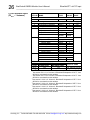
1
BusWorks® 900EN Series – EtherNet/IP™ 10/100Mbps Industrial Ethernet I/O Modules Model 965EN-6006 6 Channel mV/TC Input Model 965EN-6004 4 Channel mV/TC Input USER’S MANUAL EtherNet/IP CONFORMANCE TESTED™ ACROMAG INCORPORATED 30765 South Wixom Road P.O. BOX 437 Wixom, MI 48393-7037 U.S.A. Copyright 2004, Acromag, Inc., Printed in the USA. Data and specifications are subject to change without notice. Tel: (248) 295-0880 Fax: (248) 624-9234 8500-751-E12L019 2 BusWorks® 965EN Module User’s Manual EtherNet/IP™ mV/TC Input __________________________________________________________________ TABLE OF CONTENTS Symbols on equipment: ! IMPORTANT SAFETY CONSIDERATIONS You must consider the possible negative effects of power, wiring, component, sensor, or software failure in the design of any type of control or monitoring system. This is very important where property Loss or human life is involved. It is important that you perform satisfactory overall system design and it is agreed between you and Acromag, that this is your responsibility. GETTING STARTED Means “Refer to User’s Manual (this manual) for additional information”. The information of this manual may change without notice. Acromag makes no warranty of any kind with regard to this material, including, but not limited to, the implied warranties of merchantability and fitness for a particular purpose. Further, Acromag assumes no responsibility for any errors that may appear in this manual and makes no commitment to update, or keep current, the information contained in this manual. No part of this manual may be copied or reproduced in any form without the prior written consent of Acromag, Inc. EtherNet/IP CONFORMANCE TESTED™ Windows® is a registered trademark of Microsoft Corporation. The following is a trademark under license by ODVA: EtherNet/IP™. All trademarks are the property of their respective owners. MOUNTING AND DIMENSIONS……………………… CONTROLS & INDICATORS..………………………… ISOLATION BARRIERS..………………………………. CONNECTIONS…………………………………………. DIN-Rail Mounting And Removal……………… Network…………………………………………….. Power……………………………………………….. Analog Inputs……………………………………... Earth Ground..………………………………….…. WEB BROWSER………………………………………... Home Page………………………………………… Password Configuration Page.………………... Network Configuration Page…………………… Discussion Topic – IP Addressing……………. Test Page………………………………………….. Calibration Page………………………………….. Input Calibration………………………………….. CJC Calibration…………………………………… TROUBLESHOOTING………………………………….. Diagnostics Table……………………………..…. Trouble Browsing Your Module?..................... Getting Out Of Trouble………………………….. 3 3 3 4 4 4 6 6 7 7 7 8 9 11 13 14 16 17 19 19 20 20 TECHNICAL REFERENCE KEY FEATURES………………………………………… HOW IT WORKS………….…………………………….. ETHERNET/IP…………………………………………… Object Models………..…….….…………………. EDS File (Electronic Data Sheet)………………. MODBUS TCP/IP………..……………………………… Modbus Registers..……………………………… Register Functions………………………………. Register Mirroring……….……………………….. Register Data Types…………..………………… Register Map……………………………………… SPECIFICATIONS………………………………………. Model Numbers….……………………………….. Analog Inputs..………………....………………… General Specifications………………………….. Enclosure and Physical…………………………. Agency Approvals…..……………………………. Environmental…………………………………….. Ethernet Interface………………………………… Controls & Indicators……………………………. ACCESSORY CABLES..………………………………. 21 22 23 23 31 33 33 33 34 35 36 46 46 46 47 48 48 48 49 50 51 _______________________________________________________________________________________ Acromag, Inc. Tel:248-295-0880 Fax:248-624-9234 Email:[email protected] http://www.acromag.com BusWorks® 965EN Module User’s Manual EtherNet/IP™ mV/TC Input ___________________________________________________________________ TB4 ACT LINK MOUNTING AND DIMENSIONS TB3 DC- SLAVE ADDRESS (HEX) CJC-2 DC+ LSD MSD 33 32 31 GND IN4- IN4+ INPUTS 4, 5 Unit mounts to “T” type DIN rails (35mm, type EN50022). PWR (Model 965EN-6006 Only) 3.75 (95.3) CL 4.68 (118.9) ST IN5- RUN IN5+ 46 45 44 43 42 41 TB3 TB4 Acromag Model 965EN-6006 Shown (965EN-6004 is Similar) Units may be mounted sideby-side on 1-inch centers. DFT RST IN3- IN2- WARNING: IEC Safety Standards may require that this device be mounted within an approved metal enclosure or sub-system, particularly for applications with exposure to voltages greater than or equal to 75VDC or 50VAC. 21 22 23 24 25 26 TB2 TB1 1.05 (26.7) IN3+ TB2 11 12 13 14 15 16 INPUTS 2, 3 IN2+ CJC-1 IN1- IN0- IN1+ INPUTS 0, 1 IN0+ TB1 2.34 (59.4) CJC-0 ETHERNET 3.90 (99.1) "T" RAIL DIN MOUNTING DIN EN 50022, 35mm 4.35 (110.5) NOTE: Dimensions Are INCHES (MILLIMETERS). MODEL 965EN ENCLOSURE DIMENSIONS TB4 TB3 CJC-2 INPUTS 4, 5 TB3 DC- SLAVE ADDRESS (HEX) DC+ LSD MSD 33 32 31 GND IN4- IN5- ST IN4+ 46 45 44 43 42 41 RUN TB4 RUN/PWR LED (GREEN) MODULE STATUS LED (YELLOW) IN5+ Acromag Green Run LED is ON if power is on and will blink in “wink” ID mode. REMOVABLE (PLUG-IN TYPE) TERMINAL BLOCKS IN3- IN3+ IN2- TB2 11 12 13 14 15 16 INPUTS 2, 3 IN2+ CJC-1 IN1- IN1+ RJ45 ETHERNET CONNECTOR INPUTS 0, 1 IN0- CJC-0 IN0+ ETHERNET Model 965EN-6006 Shown (965EN-6004 is Similar) TB1 DFT RST ETHERNET ACTIVITY LED (YELLOW) AND LINK LED (GREEN) RESET/DEF ADDRESS TOGGLE SWITCH: TOGGLE RIGHT TO RESET TOGGLE LEFT TO SET DEFAULT ADDRESS 21 22 23 24 25 26 Yellow ST LED blinks ON/OFF if module is in default mode and stays ON if an input is out of range. Green LINK LED ON if autonegotiation has successfully established a connection. TB2 TB1 CONTROLS & INDICATORS PWR (Model 965EN-6006 Only) ACT LINK 3 The toggle switch is used to toggle the module into or out of Default Mode (toggle left), or to reset the module (toggle right). In Default Communication Mode, the yellow ST LED blinks slowly and the module assumes a fixed static IP address of “128.1.1.100”, a default subnet mask of “255.255.255.0”, a default username of “User”, and a default password of “password00”. DC PWR ANALOG I/O Yellow ACT LED signals PHY network Activity (busy). ISOLATION BARRIERS TB4 TB3 INPUTS 4, 5 DC+ GND DC- 36 35 34 33 32 31 TB4 IN4- IN4+ IN5- IN5+ 46 45 44 43 42 41 PWR CJC-2 TRANSFORMER (Model 965EN-4006 Only) 5V/3V TRANSFORMER 965EN ISOLATION DIAGRAM 11 12 13 14 15 16 The input circuit, network, and power circuit are isolated from each other for safety and noise immunity. IN3- IN3+ IN2- INPUTS 2, 3 IN2+ CJC-1 IN1- IN1+ IN0- INPUTS 0, 1 IN0+ TB1 CJC-0 TB2 NETWORK TX RX TB3 Dashed Lines denote isolation barriers. 21 22 23 24 25 26 TB2 TB1 ANALOG I/O ANALOG I/O _______________________________________________________________________________________ Acromag, Inc. Tel:248-295-0880 Fax:248-624-9234 Email:[email protected] http://www.acromag.com PUSH MODULE REMOVAL FROM DIN RAIL DC- DC+ 33 32 31 GN D 46 45 44 43 42 41 TB3 USE YOUR FINGER TO APPLY DOWNWARD PRESSURE HERE AS YOU LIFT AND TILT MODULE TO REMOVE IT FROM RAIL TB4 DIN-Rail Mounting & Removal When attaching the module to the T-type DIN rail, angle the top of the unit towards the rail and locate the top groove of the adapter over the upper lip of the rail. Firmly push the unit towards the rail until it snaps into place. To remove, first separate the input terminal block(s) from the bottom side of the module to create a clearance to the DIN mounting area. Next, while holding the module in place from above, insert a screwdriver into the lower arm of the DIN rail connector and use it as a lever to force the connector down until the unit disengages from the rail (do not twist the screwdriver to avoid damaging plastic). PWR "T" TYPE DIN RAIL Any Series 9XXEN Ethernet Module 11 12 13 14 15 16 TB2 CONNECTIONS TB1 4 BusWorks® 965EN Module User’s Manual EtherNet/IP™ mV/TC Input __________________________________________________________________ 21 22 23 24 25 26 Remove Terminal Blocks On This Side To Provide Clearance PRY WITH SCREWDRIVER INSERTED IN SLOT HERE (DO NOT TWIST TO AVOID DAMAGING PLASTIC TAB) PUSH SCREWDRIVER AS SHOWN TO TILT AND LIFT MODULE OFF RAIL Network For 100Base-TX systems, use data grade Unshielded Twisted-Pair (UTP) wiring that has a 100Ω characteristic impedance and meets the EIA/TIA Category Five wire specifications. It is recommended that you use a crossover CAT-5/5E cable to connect this device to your PC. For 10Base-T systems, you may use Category 3, Category 4, or Category 5/5E UTP/STP cable. 8 1 ETHERNET PORT 8 RJ-45 CONNECTOR 1 RJ45 MDI CONNECTIONS 1 Transmit + 2 Transmit 3 Receive + 4 Not Used 5 Not Used SPEED 6 Receive 10Base-T 7 Not Used 100Base-TX 8 Not Used CLIP DISTANCE 100M 100M CABLE CAT 3, CAT 4, or CAT 5 UTP CAT 5/5e UTP/STP In either case, you are limited to 100 meters between any two devices. The Ethernet port of this module is wired MDI and does not include automatic crossover. The Ethernet port of your PC is also wired MDI and may not include automatic crossover. As such, you must use a crossover cable like that shown below when connecting this device directly to a PC. A crossover cable simply connects the differential transmit pair on each end, to the receive pair on the opposite end. CROSSOVER CABLE FOR MDI TO MDI OR MDI-X TO MDI-X Use a standard (direct) cable when connecting to a hub or switch port, which are generally wired MDI-X. CROSSOVER CONNECTIONS RJ45 (Clip Side Down) RJ45 (Clip Side Down) 8 8 1 6 2 1 3 1 6 1 FOR DIRECT PC TO ETHERNET MODULE CONNECTIONS 1 2 3 8 1 8 PINS: 1 TO 3 2 TO 6 3 TO 1 6 TO 2 _______________________________________________________________________________________ Acromag, Inc. Tel:248-295-0880 Fax:248-624-9234 Email:[email protected] http://www.acromag.com 5 BusWorks® 965EN Module User’s Manual EtherNet/IP™ mV/TC Input ___________________________________________________________________ Refer to the Accessory Cables section at the back of this manual for more information on accessory cables, including patch and crossover cables available from Acromag and other vendors. HOST PC CONNECTED DIRECTLY TO A MODULE CONNECTIONS Network Acromag RUN Note: This MDI-to-MDI connection requires the use of a crossover cable. The ethernet port of this module is not automatic MDI/MDI-X crossover and is wired MDI. ACT LINK CAT-5 UTP CABLE UP TO 100 METERS HOST PC Acromag 965EN-6006 Ethernet Module. ST DFT RST (Use Crossover Cable) ETHERNET TIP: You can significantly enhance the EMI/RFI performance of your network connections by using Category 5E STP cable (Shielded Twisted Pair) with shielded RJ45 plug connectors. This will also help to protect your installation from damage due to ESD (Electro-Static Discharge). The use of shielded cable is strongly recommended for installations in harsh industrial environments and/or in the presence of strong electrical fields. You can use an Ethernet switch or switching hub to build a network of Ethernet modules, similar to that shown below. This drawing shows how to network-connect Acromag Series 9xxEN modules to a 5-port Ethernet switch (Acromag Model 900EN-S005). Note that the 900EN-S005 switch includes automatic MDI/MDI-X crossover and a straight-through or crossover cable(s) may be used to connect to the modules and the PC. ETHERNET SWITCH IMPORTANT: IF THE HOST PC CONNECTS DIRECTLY TO THE MODULE, YOU MUST USE A CROSS-CONNECT CABLE (MDI-X), AS BOTH THE PC AND THE 9XXEN MODULE ETHERNET PORTS ARE WIRED MDI. ETHERNET SWITCHES AND HUBS ARE WIRED MDI-X. THE ACROMAG ETHERNET SWITCH IS AUTOMATIC MDI/MDI-X AND ELIMINATES THE NEED FOR MAKING A DISTINCTION BETWEEN THE USE OF STRAIGHT-THROUGH (MDI) AND CROSSOVER (MDI-X) CABLE CONNECTIONS. TB3 DC+ X5 LK / ACT 100M COL ETHERNET SW ITCH X1 X2 X3 X4 Acromag 9xxEN-4012 or 9xxEN-6012 Ethernet Modules. Acromag RUN CH. I/O STATUS Because the Acromag ethernet switch 900EN-S005 is automatic MDI/MDI-X crossover, use of a direct (straight-through) or crossover cable is permissible. The ethernet ports of this switch are automatic MDI/MDI-X crossing and do not require crossover cables. X3 X5 HOST PC POWER X2 X5 Acromag 900EN-S005 5-Port Ethernet Switch or equivalent. CAT-5 UTP CABLE UP TO 100 METERS ST 8 9 10 11 ACT LINK RS DA Acromag RUN (Straight-Through or Crossover Cable) Order Acromag Cable Model 5035-355 CAT-5 UTP CABLE UP TO 100 METERS The ethernet port of these modules are not automatic MDI/MDI-X crossover, but the use of an auto-crossing switch eliminates the need to make a distinction between straight-through and crossover cables. 01 23 4 567 ETHERNET CH. I/O STATUS X1 34 33 32 31 DC+ P1 X4 CAT-5 UTP CABLE UP TO 100 METERS S2 DIP SW S1/S2 PGM CFG OPTIONS PORT DC- S1 RUN GND Acromag The ethernet port of the PC is generally not automatic MDI/MDI-X crossover and is wired MDI. PUSH TO RESET USE OF AN ETHERNET SWITCH TO NETWORK A HOST PC TO MORE THAN ONE MODULE ST 0 1 23 4 567 8 9 10 11 ACT LINK RS DA Acromag CAT-5 UTP CABLE UP TO 100 METERS ETHERNET CH. I/O STATUS RUN Acromag offers a straight-through patch cable (Model 5035-355), or a crossover cable (Model 5035-360) for use with Series 9xxEN modules. (Straight-Through or Crossover Cable) ST 01 23 4 567 8 9 10 11 ACT LI NK RS DA Acromag CAT-5 UTP CABLE UP TO 100 METERS (Straight-Through or Crossover Cable) ETHERNET CH. I/O STATUS RUN (Straight-Through or Crossover Cable) ST 01 23 4 567 8 9 10 11 ACT LINK RS DA ETHERNET _______________________________________________________________________________________ Acromag, Inc. Tel:248-295-0880 Fax:248-624-9234 Email:[email protected] http://www.acromag.com Power Voltage 15VDC 18VDC 24VDC 36VDC Current 120mA 100mA 78mA 57mA Connect 15-36V DC to the power terminals labeled DC+ & DC-. Observe proper polarity. For supply connections, use No. 14 AWG wires rated for at least 75C. CAUTION: Do not exceed 36VDC peak. TB3 15 TO 36VDC + TB3 DC+ DC- PWR CONNECTIONS 33 32 31 6 BusWorks® 965EN Module User’s Manual EtherNet/IP™ mV/TC Input __________________________________________________________________ INPUT POWER IS ISOLATED GND EARTH GROUND CAUTION: Risk of Electric Shock – More than one disconnect switch may be required to de-energize this equipment before servicing. IMPORTANT – External Fuse: If unit is powered from a supply capable of delivering more than 1A to the unit, it is recommended that this current be limited via a high surge tolerant fuse rated for a maximum current of 1A or less (for example, see Bel Fuse MJS1). DC VOLTAGE (Volts) SHIELDED CABLE + V - - NOTE 1 C JC -0 + IN0+ IN0IN1+ IN1- IN PU TS 0, 1 +/-100mV, +/-1V DC INPUT TC INPUT NOTE 1 C JC -0 TB1 IN0+ IN0IN1+ IN1- IN PU TS 0, 1 Inputs are not isolated channel-to-channel, except for small common mode voltages less than ±5V peak. Connect analog input signals to the input terminals as shown below according to your model. 16 15 14 13 12 11 Input is a type J, K, T, E, R, S, B, or N thermocouple, ±100mV DC, or ±1V DC. 16 15 14 13 12 11 Analog Inputs TB1 NOTE 1: THIS GROUND CONNECTION IS RECOMMENDED FOR BEST RESULTS. IF SENSORS ARE INHERENTLY CONNECTED TO GROUND, USE CAUTION AND AVOID MAKING ADDITIONAL GROUND CONNECTIONS WHICH COULD GENERATE GROUND LOOPS AND MEASUREMENT ERROR. _______________________________________________________________________________________ Acromag, Inc. Tel:248-295-0880 Fax:248-624-9234 Email:[email protected] http://www.acromag.com BusWorks® 965EN Module User’s Manual EtherNet/IP™ mV/TC Input ___________________________________________________________________ Connect Earth Ground as shown in the connection drawings above. Additionally, connect the GND terminal (TB3-33) to earth ground. The ground connections noted are recommended for best results. If sensors are already grounded, use caution and avoid making additional ground connections which could create ground loops. The plastic module housing does not require earth ground. This module supports Modbus over TCP/IP. You may use your own software to issue Modbus command to this module (see Modbus Registers), or you may use a standard web browser, as these modules have built-in web pages that allow you to setup, control, and calibrate the module. Simply execute your web browser, type the IP address assigned to your module in the “Address” window (http://128.1.1.100/ for our example), click [Go], and you will be presented with a Home Page window similar to that shown below: 7 Earth Ground Warning: To comply with safety and performance standards, use shielded cable and connect earth ground as noted. Failure to use good wiring and grounding practices may be unsafe and hurt performance. WEB BROWSER Home Page The Home Page provides buttons to access the other web pages of this module that are used to configure the network parameters, change the user name and password, calibrate the module, and operate/test the module. For each new browser session that accesses the Home Page of this module, you will be presented with a window prompting you to enter the current User Name and Password as shown below. This information is required before the program will allow you to make any other selections. The default user name and password is “User” and “password00” respectively. After entering these defaults, you may wish to invoke the Password Configuration Page to change these parameters to something more meaningful to you. _______________________________________________________________________________________ Acromag, Inc. Tel:248-295-0880 Fax:248-624-9234 Email:[email protected] http://www.acromag.com 8 BusWorks® 965EN Module User’s Manual EtherNet/IP™ mV/TC Input __________________________________________________________________ WEB BROWSER Home Page IMPORTANT: If you forget your installed user name & password, you can always toggle the module into default mode via the default mode toggle switch at the front of the module. Then the password and username will revert to the original defaults noted above, allowing you to re-invoke the Password Configuration Page and change the username and password settings as required. Password Configuration Page Use up to 20 alphanumeric characters (case sensitive) to specify your username, and 10 alphanumeric characters (case sensitive) to specify a password. You will have to type in these entries twice to help prevent errors. Click the submit button to write your changes to the module. After completing your username/password changes, click on the appropriate button at the bottom of the page to select another web page. If you made changes, you may be prompted to re-enter your new username and password before being permitted to move to other pages. _______________________________________________________________________________________ Acromag, Inc. Tel:248-295-0880 Fax:248-624-9234 Email:[email protected] http://www.acromag.com BusWorks® 965EN Module User’s Manual EtherNet/IP™ mV/TC Input ___________________________________________________________________ After setting your username and password, you can click the “Network Configuration Page” button to set the network configuration parameters for the module. You may have to consult your network administrator to complete the contents of this page. 9 WEB BROWSER Network Configuration Note that Acromag Series 9xxEN Ethernet I/O modules may take from 3-30 seconds to boot upon power-up, depending on your network configuration and whether a DHCP server is present. An IP Address is a unique identification number for any host (this module) on any TCP/IP network (including the internet). The IP address is made up of four octets (8 bits), each octet having a value between 0-255 (00H-FFH). It is expressed here in decimal form, with a period placed between octets. A Static IP Address is as the name implies—static, and represents a unique fixed IP Address that is generally assigned by your service provider or system administrator. The default static IP address assigned to this module from the factory is 128.1.1.100 (refer to product side label). NOTE: In order to network your PC with an Acromag module, you may have to consult with your network administrator and either temporarily change your TCP/IP configuration (see TCP/IP Properties of Network Configuration in Windows), or create a separate private network using a second network adapter installed in your PC (recommended). The necessary steps will vary with your operating system. Refer to Acromag Application Note 8500-734 to help accomplish this (located on the CDROM shipped with your module or via download from our web site at www.acromag.com). The DNS Server refers to the IP address of the Domain Name Server used on this network. A DNS server relates symbolic names to actual IP addresses, while the DHCP server is responsible for dynamically passing out IP addresses. _______________________________________________________________________________________ Acromag, Inc. Tel:248-295-0880 Fax:248-624-9234 Email:[email protected] http://www.acromag.com 10 BusWorks® 965EN Module User’s Manual EtherNet/IP™ mV/TC Input __________________________________________________________________ WEB BROWSER Network Configuration This module can be placed into a default communication mode via the DFT toggle switch at the front of the module. Default Mode uses a static IP address of “128.1.1.100”, a default subnet mask of “255.255.255.0”, a default username “User”, and a default password “password00”. A Subnet Mask is used to subdivide the host portion of the IP address into two or more subnets. The subnet mask will flag the bits of the IP address that belong to the network address, and the remaining bits correspond to the host portion of the address. The unique subnet to which an IP address refers to is recovered by performing a bitwise AND operation between the IP address and the mask itself, with the result being the sub-network address. The Host Name is the name to be assigned to this host if its address happens to be assigned dynamically using DHCP. Gateway refers to the IP Address of the gateway, if your local area network happens to be isolated by a gateway. Typically, it is assigned the first host address in the subnet. If a gateway is not present, then this field should contain an unused address within the host subnet address range. The Active IP Address refers to the current IP Address being used by this host, as opposed to any new assignments being made via this page. The MAC Address refers to the Media Access Control Address that uniquely identifies the hardware of this device. This is a unique fixed address assigned to this module at the factory. In IEEE 802 networks, the Data Link Control (DLC) layer of the OSI Reference Model is divided into two sublayers: the Logical Link Control (LLC) layer, and the Media Access Control (MAC) layer. The MAC layer interfaces directly with the network media (each different type of network media requires a different MAC layer). By default, the module is setup to use Static IP Addressing and a Static IP Address of 128.1.1.100. You can optionally choose to have the IP address assigned dynamically via DHCP/BOOTP or DHCP/BOOTP w/Fallbacks. This will also require that you specify a valid Host Name. Note that DHCP/BOOTP w/Fallback will revert to the static IP address if your DHCP or BOOTP server cannot be found at the address specified. In general, BOOTP (Bootstrap Protocol) refers to an internet protocol that enables a diskless workstation to discover its own IP address, the address of a BOOTP server on the network, and a file to be loaded into memory to boot the machine. This enables the workstation or device server to boot without requiring a hard or floppy disk drive. BOOTP works similar to DHCP, but is usually found in older systems. This protocol is defined by RFC 951. DHCP refers to Dynamic Host Configuration Protocol and is a method used to dynamically assign temporary numeric IP addresses as required. With dynamic addressing, a device can have a different IP address every time it connects to the network. In some systems, it can even change while it is still connected. In general, a DHCP server maintains a pool of shared IP addresses which are dynamically assigned and recycled. When a DHCP device wants to use a TCP/IP application, it must request an IP address from the DHCP server. The DHCP server will check the shared supply, and if all addresses are in use, the server will send a busy signal to the client which tells it to try again later. Thus, although static IP addresses will ensure a connection every time, dynamic addresses will not. _______________________________________________________________________________________ Acromag, Inc. Tel:248-295-0880 Fax:248-624-9234 Email:[email protected] http://www.acromag.com BusWorks® 965EN Module User’s Manual EtherNet/IP™ mV/TC Input ___________________________________________________________________ DHCP also supports a combination of static and dynamic IP addresses. You can select “DHCP/BOOTP w/Fallback” and automatically revert to either a static IP address, or the last DHCP assigned IP address, if the DHCP or BOOTP server cannot be found. 11 WEB BROWSER Network Configuration DNS refers to the Domain Name System or Domain Name Server and refers to the system used to associate an alphanumeric character string with a numeric IP address. The DNS is actually a distributed database of domain names and corresponding IP addresses. These servers contain information on some segment of the domain name space and make this information available to clients called resolvers. For example, the DNS allows us to use “Acromag.com” as an IP address rather than a complicated number string. The unit includes a default address toggle switch to cause the module to assume a preset default factory address. This switch is at the front of the module and is used to toggle the module into, or out of Default Mode. If you use the toggle switch at the front of the module to place the module in default mode, then “Default Communications Mode” will be indicated at the bottom of this screen. Click the Submit button to complete any changes made on this page. Click the Wink On/Off button to toggle the module in/out of “wink” ID mode. In this mode, the module’s green RUN LED will blink to confirm identification as an aide to locating a specific module on a network. You may refer to the following section to learn more about IP Addressing terms and concepts, or you can skip ahead to the Test Page. A host is any device on any network. On TCP/IP networks, each host has one or more unique IP addresses. This module connected to an Ethernet network may be referred to as a host. Discussion Topic – IP Addressing An IP Address is a unique identification number for any host (this module) on any TCP/IP network (including the internet). The IP address is made up of four octets (8 bits), each octet having a value between 0-255 (00H-FFH). The IP address is comprised of two parts: the network address (first part) and the host address (last part). The number of octets of the four total that belong to the network address depend on the Class definition (see below). A Static IP Address is as the name implies—static. That is, it is a unique IP Address that is assigned by a service provider and never changes. A Dynamic IP Address is an address that is temporarily assigned to a user by a service provider each time a user connects. A Subnet is a contiguous string of IP addresses. The first IP address in a subnet is used to identify the subnet, while the last IP address in a subnet is always used as a broadcast address. Anything sent to the last IP address of a subnet is sent to every host on that subnet. _______________________________________________________________________________________ Acromag, Inc. Tel:248-295-0880 Fax:248-624-9234 Email:[email protected] http://www.acromag.com 12 BusWorks® 965EN Module User’s Manual EtherNet/IP™ mV/TC Input __________________________________________________________________ Discussion Topic – IP Addressing Subnets are further broken down into three size classes based on the 4 octets that make up the IP address. A Class A subnet is any subnet that shares the first octet of the IP address. The remaining 3 octets of a Class A 24 subnet will define up to 16,777,214 possible IP addresses (2 – 2). A Class 16 B subnet shares the first two octets of an IP address (providing 2 – 2, or 65534 possible IP addresses). Class C subnets share the first 3 octets of an IP address, giving 254 possible IP addresses. Recall that the first and last IP addresses are always used as a network number and broadcast address respectively, and this is why we subtract 2 from the total possible unique addresses that are defined via the remaining octet(s). TIP: The first node (0) and node 10 are typically reserved for servers and may yield poor results if used. The last node is reserved as a broadcast address for the subnet. For our example, the default IP address of this module is 128.1.1.100. If we assume that this is a Class C network address (based on the default Class C subnet mask of 255.255.255.0), then the first three numbers represent this Class C network at address 128.1.1.0, the last number identifies a unique host/node on this network (node 100) at address 128.1.1.100. A Subnet Mask is used to determine which subnet an IP address belongs to. The use of a subnet mask allows the network administrator to further divide the host part of this address into two or more subnets. The subnet mask flags the network address portion of the IP address, plus the bits of the host part that are used for identifying the sub-network. By convention, the bits of the mask that correspond to the sub-network address are all set to 1’s (it would also work if the bits were set exactly as in the network address). It’s called a mask because it can be used to identify the unique subnet to which an IP address belongs to by performing a bitwise AND operation between the mask itself, and the IP address, with the result being the subnetwork address, and the remaining bits the host or node address. For our Example, if we wish to further divide this network into 14 subnets, then the first 4 bits of the host address will be required to identify the subnetwork (0110), then we would use “11111111.11111111.11111111. 11110000” as our subnet mask. This would effectively subdivide our Class C network into 14 subnetworks of up to 14 possible nodes each. With respect to the default settings of this module: Subnet Mask 255.255.255.0 (11111111.11111111.11111111.00000000) IP Address: 128.1.1.100 (10000000.00000001.00000001.01100100) Subnet Address: 128.1.1.0 (1000000.00000001.00000001.00000000) The subnetwork address of 128.1.1.0 has 254 possible unique node addresses (we are using node 100 of 254 possible). Nodes 0 (first node) and 10 are typically reserved for servers and may yield poor results if used. Node 255 (last node in the subnet) is reserved as a broadcast address for the subnet. _______________________________________________________________________________________ Acromag, Inc. Tel:248-295-0880 Fax:248-624-9234 Email:[email protected] http://www.acromag.com BusWorks® 965EN Module User’s Manual EtherNet/IP™ mV/TC Input ___________________________________________________________________ After completing your username and password assignment, plus your network configuration parameters, you can use the Test Page to operate your module. The Test Page will allow you to read inputs, enable/disable CJC, set break detect direction, and change input ranges of this model. Use the scroll bar on the right to scroll down the page as shown below: 13 WEB BROWSER Test Page TIP: Viewing a module’s web page is treated similar to viewing a web page on the internet. The first time you open a page, its image is stored as a temporary internet file in PC memory. However, each subsequent attempt to view that page will need to automatically update that image, especially when making configuration changes. With Internet Explorer, click the “Internet Options” of the “Tools” menu, select the “General” tab, locate the “Temporary Internet Files” information and click on the “Settings” button. Then select “Automatically” under “Check for newer versions of stored pages:”. Then click [OK] to return to the “General” screen, and click [OK] again to save your settings. Note that the 6 or 4 channels of this module are divided into two groups of 3 channels each (ports). A CJC sensor is included for each channel pair. Input signals for each channel are indicated to 3 decimal places (voltage inputs), or to 1 decimal place (TC inputs), similar to that shown above. _______________________________________________________________________________________ Acromag, Inc. Tel:248-295-0880 Fax:248-624-9234 Email:[email protected] http://www.acromag.com 14 BusWorks® 965EN Module User’s Manual EtherNet/IP™ mV/TC Input __________________________________________________________________ WEB BROWSER Test Page Note (TC Break): Internally, TC input values are represented via 16-bit signed integers with a resolution of 0.1C/lsb and a possible range of –3276.8C to +3276.7C. As such, a count of 0-7FFFH is a positive number, while 8000-FFFFH is a negative number. The downscale (break) detent is 32768 for all TC types. However, the upscale break over-range count is trimmed to a reasonable range value according to the TC type as follows: 12895 (J), 20068 (K), 6820 (T), 31190 I, 32767 (S), 20205 (E), 22824 (B), and 21002 (N). Calibration Page Note that channels 0, 1, & 2, and channels 3, 4, & 5 (every group of 3 channels) share the same input configuration, but the configuration may vary between the two groups. On the four channel model, the fourth channel may differ from the first 3 channels. Break detection applies to all channels together. CJC 0 is used for channels 0 & 1, CJC 1 for channels 2 & 3, and CJC 2 for channels 4 & 5. IMPORTANT: The input signal indicated only reflects the level of the inputs at the moment this screen is invoked and this does not continuously update. You can click your browser’s refresh button to get a new input update. Note that the ACT LED will blink each time you hit refresh. You can use the Port Configuration Control of this page to change the input range for the channels on a port-by-port basis. For the 965EN shown, you may select from a voltage range of ±100mV, or ±1V, or TC type J, K, T, R, S, E, B, or N thermocouple. Note that your range selection will apply to all channels of the entire port (group of three channels). You may also select the break detect direction by selecting UP for upscale, or DOWN for downscale (applies to all channels together). Click on “submit” to execute your range and/or TC break changes. The Calibration Page will allow you to recalibrate each channel’s zero and span signal as required. Simply select the channel to be calibrated, choose zero or span, apply the zero or full-scale signal to the input, then click calibrate. For best results, always calibrate zero before span. IMPORTANT: This module has already been calibrated at the factory and recalibration is not normally required, except as necessary to correct for long term component aging, or to satisfy your company’s maintenance requirements. Do not attempt to recalibrate this module unless absolutely required, as miscalibration will negatively affect the module’s performance. Use the scroll bar on the right to scroll down the page as shown below: _______________________________________________________________________________________ Acromag, Inc. Tel:248-295-0880 Fax:248-624-9234 Email:[email protected] http://www.acromag.com BusWorks® 965EN Module User’s Manual EtherNet/IP™ mV/TC Input ___________________________________________________________________ 15 WEB BROWSER Calibration Page If recalibration of any input is required, all applicable ranges should be done. The following table gives the calibration values for these models. These represent the input signals required to calibrate the range endpoints. Your success in recalibrating the input will strongly depend upon the accuracy and precision of your signal source. Input Calibration Values For Supported Input Ranges Available INPUT CALIBRATION POINTS Input LOW CALIBRATION HIGH CALIBRATION Ranges POINT (Cal Lo) POINT (Cal Hi) Type J TC 0.0 (0.000mV) 700.0 (39.130mV) Type K TC 0.0 (0.000mV) 1300.0 (52.398mV) Type T TC 0.0 (0.000mV) 390.0 (20.252mV) Type R TC 0.0 (0.000mV) 1700.0 (20.215mV) Type S TC 0.0 (0.000mV) 1700.0 (17.942mV) Type E TC 0.0 (0.000mV) 950.0 (72.593mV) Type B TC 260 (0.317mV) 1700 (12.426mV) Type N TC 0.0 (0.000mV) 1200.0 (43.836mV) 100 mVDC -100.000 mVDC 100.000 mVDC ±1.00 VDC -1.00V DC +1.00V DC IMPORTANT: Be sure to turn CJC off prior to calibrating any TC or voltage ranges. For best results, be sure to use a precision millivoltage source capable of reproducing the nominal thermoelectric endpoint signals at least as accurate as the module itself (better than ±0.1% of span). In addition, always allow the module to warm up several minutes prior to calibration. There are nine calibration channels for the 965EN-6006, six input channels plus three temperature references (CJC). There are six calibration channels for the 965EN-4004, four input channels plus two temperature references (CJC). Input channels are calibrated differently than temperature reference channels. _______________________________________________________________________________________ Acromag, Inc. Tel:248-295-0880 Fax:248-624-9234 Email:[email protected] http://www.acromag.com 16 BusWorks® 965EN Module User’s Manual EtherNet/IP™ mV/TC Input __________________________________________________________________ WEB BROWSER Input Calibration You can choose to use the web browser calibration page to accomplish calibration as described in Method 1 at right (easiest), or via direct register access as described in Method 2 below. Note that because of equivalent A/D gain selections between some ranges, Type K and Type N are calibrated at the same time Type J is calibrated, and Type R and Type S are calibrated at the same time Type T is calibrated. Also, Type J and the ±1V ranges must be calibrated prior to calibrating the CJC references. Method 1 – Calibration Using The Built-In Browser Interface: 1. Make sure that the range that needs calibrating is currently selected. 2. Turn CJC off. 3. Bring up browser interface and select the calibration page. 4. Apply either the Cal LO or Cal HI input signal to the channel to be calibrated. Calibrate the low endpoint signal first, before the high endpoint signal. 5. Wait about 10 seconds for the input to settle and be read. 6. Click on the channel number and select either low or high calibration. 7. Click on the “Calibrate” button. The page will refresh and calibration may continue. Repeat this process for the other endpoint (Cal HI). 8. Repeat steps 4-7 for the other input channels to be calibrated for this same range. 9. Repeat steps 1-7 until all input ranges have been calibrated. Note that Type K and Type N are calibrated by calibrating Type J, and type R and Type S are calibrated by calibrating by calibrating Type T. In the following procedures, information that is specific to the EtherNet/IP interface is contained in braces [ ]. Method 2 – Calibration Via Modbus TCP/IP and [EtherNet/IP] interface: 1. Write to the TC Break & CJC Configuration Register [attribute] to turn CJC OFF and set the break detection as required by your application. 2. Write to the appropriate Input Range Register [attribute] to select the input range to be calibrated for your channel of interest. 3. Write 24106 (5E2AH) into the Calibration Access Register [Discrete Output Word 0] to remove write protection from the calibration registers. 4. Apply the zero calibration signal (Cal Lo, see table) to the input to be calibrated and allow the input to settle about 10 seconds. 5. Write a 16-bit value to the Zero Calibration Register [Discrete Output Word 2] with a set bit in the bit position that corresponds to the channel number to be calibrated (one channel at a time). If you were calibrating the zero of channel 5, you would write 0x0020 to the Zero Calibration Register [Discrete Output Word 2]. The module will replace calibration coefficients immediately, no reset is needed. 6. Apply the full-scale calibration signal (Cal Hi, see table) to the input to be calibrated and allow the input to settle about 10 seconds. 7. Write a 16-bit value to the Span Calibration Register [Discrete Output Word 1] with a set bit in the bit position that corresponds to the channel number of the channel to be calibrated (one channel at a time). For example, if you wanted to calibrate the span of channel 0, write 0x0001 to the Span Calibration Register [Discrete Output Word 1]. 8. Repeat steps 4-7 for the other channels as required. 9. Repeat steps 2-8 for the next range as required. 10. When finished calibrating, write 0x0000 to the Calibration Access Register (Holding Register 21) [Discrete Output Word 0] to replace write protection to the calibration registers [values] and prevent miscalibration. _______________________________________________________________________________________ Acromag, Inc. Tel:248-295-0880 Fax:248-624-9234 Email:[email protected] http://www.acromag.com BusWorks® 965EN Module User’s Manual EtherNet/IP™ mV/TC Input ___________________________________________________________________ 17 The 965EN-6004 model includes two CJC reference sensors. The 965EN6006 model includes three CJC reference sensors. These reference sensors are calibrated separate from the inputs, but use the adjacent input channels 0, 2, and 4, plus the ±1V and Type J TC ranges to accomplish calibration. As such, be sure the Type J TC and ±1V ranges are already calibrated at inputs 0, 2, and 4 prior to calibrating CJC. Then enable CJC and calibrate Cold Junction Compensation as follows: WEB BROWSER IMPORTANT: For best results, allow the module to warm-up for 60 minutes before calibrating cold junction compensation. Further, position the module as in the final application during warmup. Take care to isolate the unit from air drafts while calibrating it. Ambient must be between 10°C and 40°C. In order to calibrate CJC, the module ambient must be within 10°C to 40°C. Do not attempt to recalibrate CJC outside of, or near these end points, as this may negatively affect module accuracy. CJC Calibration Via Modbus TCP/IP and [EtherNet/IP] Interface: 1. Write to the TC Break & CJC Configuration Register [attribute] to turn CJC ON and set the break detection as required by your application. 2. Write to the appropriate Input Range Register [attribute] to select the TC Type J range for the input channels adjacent to the CJC sensors (inputs 0, 2, and 4)—you will use these inputs to pass your CJC calibration signal. 3. Write 24106 (5E2AH) into the Calibration Access Register [Discrete Output Word 0] to remove write protection from the calibration registers [values]. 4. Connect a Type J TC reference at 0°C (0.000mV) to inputs 0, 2, and 4 and allow the input to settle about 10 seconds. 5. Write a 16-bit value to the Tref Calibration Register [Discrete Output Word 4] with a set bit in the bit position that corresponds to the CJC channel to be calibrated (one channel at a time). If you are calibrating CJC0, you would write 0x0001 to the Tref Calibration Register [Output Word]. If calibrating CJC1, write 0x0002. If calibrating CJC2, write 0x0004. CJC Calibration Note that the module will replace the calibration coefficients immediately and no reset is needed. Further, no response will be received and Modbus will actually timeout—this is normal, as it takes several seconds to process your calibration. If calibration is successful, the input adjacent to the CJC will read 0.0°C ±0.1°C after about 10 seconds (this is input 0, 2, or 4 for CJC 0, 1, or 2). If calibration is not successful, the input adjacent to the CJC will read 1000.0°C (this is input 0, 2, or 4 for CJC 0, 1, or 2) and you must try to calibrate again. First, check that your input is a Type J TC, your module is warmed-up, your signal is 0°C (0.000mV), and you are at the correct input channel. Then retry calibration. It may be necessary to take steps to isolate the unit from air drafts during CJC calibration—for example, you may find it helpful to place a plastic bag over the unit while calibrating it. 7 Repeat step 4-5 for the other CJC sensors. _______________________________________________________________________________________ Acromag, Inc. Tel:248-295-0880 Fax:248-624-9234 Email:[email protected] http://www.acromag.com 18 BusWorks® 965EN Module User’s Manual EtherNet/IP™ mV/TC Input __________________________________________________________________ WEB BROWSER Calibration Page CJC Calibration Via Modbus TCP/IP & [EtherNet/IP] Interface…continued: 7 When finished calibrating, write 0x0000 to the Calibration Access Register (Holding Register 21), [or Discrete Output Word 0], in order to replace write protection to the calibration registers [values] and prevent miscalibration. The following table gives the equivalent thermoelectric millivoltage for supported thermocouple types at various temperatures. Thermocouple milliVoltage Versus Temperature (From NIST National Institute of Standards and Technology TC Tables) TEMP Thermoelectric milliVoltage (w/ Reference Junction at 0C) C J K T E R S B - 250 ---6.404 -6.181 -9.719 ------- 200 -7.890 -5.891 -5.603 -8.824 ------- 150 -6.499 -4.912 -4.648 -7.279 ------- 100 -4.632 -3.553 -3.378 -5.237 ------- 50 -2.431 -1.889 -1.819 -2.787 ------0 0.000 0.000 0.000 0.000 0.000 0.000 0.000 + 50 2.585 2.022 2.035 3.047 0.296 0.299 --+ 100 5.268 4.095 4.277 6.317 0.647 0.645 --+ 150 8.008 6.137 6.702 9.787 1.041 1.029 --+ 200 10.777 8.137 9.286 13.419 1.468 1.440 --+ 250 13.553 10.151 12.011 17.178 1.923 1.873 --+ 300 16.325 12.207 14.860 21.033 2.400 2.323 --+ 350 19.089 14.292 17.816 24.961 2.896 2.786 --+ 400 21.846 16.395 20.869 28.943 3.407 3.260 --+ 450 24.607 18.513 --32.960 3.933 3.743 1.002 + 500 27.388 20.640 --36.999 4.471 4.234 1.241 + 550 30.210 22.772 --41.045 5.021 4.732 1.505 + 600 33.096 24.902 --45.085 5.582 5.237 1.791 + 650 36.066 27.022 --49.109 6.155 5.751 2.100 + 700 39.130 29.128 --53.110 6.741 6.274 2.430 + 800 --33.277 --61.022 7.949 7.345 3.154 + 900 --37.325 --68.783 9.203 8.448 3.957 +1000 --41.269 --76.358 10.503 9.585 4.833 +1200 --48.828 ----13.224 11.947 6.783 +1400 --------16.035 14.368 8.952 +1600 --------18.842 16.771 11.257 +1700 --------20.215 17.942 12.462 +1750 --------20.878 18.504 13.008 +1800 ------------13.585 _______________________________________________________________________________________ Acromag, Inc. Tel:248-295-0880 Fax:248-624-9234 Email:[email protected] http://www.acromag.com BusWorks® 965EN Module User’s Manual EtherNet/IP™ mV/TC Input ___________________________________________________________________ Upon power-up, the green RUN LED should light, while a continuous blinking Run LED indicates “wink” ID mode. But if the Run LED remains OFF and correct power has been applied, then either the internal power supply has failed or a fatal processor error (firmware) has occurred. SYMPTOM Green RUN LED does not light. Continuous flashing green RUN LED. POSSIBLE CAUSE Internal +3.3V power has failed. Module in “wink” mode. Cannot communicate. Power ON at the module? Connecting cable is not a crossover cable. TIP: To check cable type, hold both ends in same position and read the wire colors through the clear portion of the plug from left to right. If colors are arranged in the same order, you have a straight cable. Wrong IP Address Many Communication Errors. Is cable segment longer than 100M? Correct Cable? Missing earth ground connection. Status LED always ON. Indicates a channel over-range condition. Cannot Browse Module. Your browser may be setup to use a proxy server for LAN communications. POSSIBLE FIX Return module for repair. Read Module Status register to verify “wink” status. Write 5555H to Wink Mode Toggle Register to toggle wink mode off/on. Check power. Is green RUN LED ON? This module’s thernet port is wired MDI. You must use a crossover cable when connecting this module to your PC or another device also wired MDI. If you are connecting to an Ethernet switch or hub, then a direct cable is used. Note: If your Link LED is ON, you have connected using the correct type of cable, but it could still be defective. Change the IP address of the module or the PC so that both match. Try the default module address of 128.1.1.100. Try another PC NIC address. Maximum distance between two nodes is limited to 100 meters with approved cable. Shielded CAT-5/5E cable or equivalent is recommended. Connect earth ground to TB3-33 GND terminal adjacent to power terminal. Terminate unused input channels as break detection at an open channel will trigger over-range. Note that over-range indication may mask default mode indication via this LED. Temporarily disable the use of a proxy server by your browser (see procedure of next page). 19 TROUBLESHOOTING Diagnostics Table If your problem still exists after checking your wiring and reviewing this information, or if other evidence points to another problem with the unit, an effective and convenient fault diagnosis method is to exchange the module with a known good unit. Acromag’s Application Engineers can provide further technical assistance if required. Complete repair services are also available from Acromag. _______________________________________________________________________________________ Acromag, Inc. Tel:248-295-0880 Fax:248-624-9234 Email:[email protected] http://www.acromag.com 20 BusWorks® 965EN Module User’s Manual EtherNet/IP™ mV/TC Input __________________________________________________________________ TROUBLESHOOTING Please refer Acromag Application Note 8500-734 for help in setting up network communication with your module (located on the CDROM shipped with your module or via download from our web site at www.acromag.com). This document gives details for changing your PC’s TCP/IP configuration in order to communicate with your module (see TCP/IP Properties of Network Configuration in Windows). Trouble Browsing Your Module? If you have carefully followed this procedure and you still cannot browse your module, you may have the web browser of your laptop or PC setup to use a proxy server when browsing the web. If you are using Internet Explorer, Refer to the “Tools” pulldown menu, select “Internet options…”, click the “Connections” tab, then click the “LAN Settings” button. Locate the Proxy server information and uncheck the box next to the statement “Use a proxy server for your LAN”. Then click [OK] to return to the “Connections” screen, and click [OK] again to save your settings. You should now be able to use Internet Explorer to browse the module as required. However, to later restore your PC’s connection to your company network, you may have to re-enable the use of a proxy server for your LAN. Getting Out Of Trouble There is no built-in error detection to prevent you from writing invalid values to a configuration register. As such, if you inadvertently write an invalid value to an internal register, you could cause the module to become inoperable under certain conditions. If this happens, in order to regain control of the module, the module can either be re-downloaded at the factory, or you can try restoring the module to its initial configuration by following this procedure: So, you think your module’s “gone wild”, follow this procedure to restore it to its initial configuration and regain control. Procedure For Restoring any 9xxEN Module to its Initial Configuration 1. 2. 3. 4. While module power is OFF, press and hold the front-panel toggle switch in the default (DFT left) position. While continuing to hold the toggle switch in the default position, apply power to the module. After a few seconds, the Status LED will begin to blink quickly and you can release the default switch at this point. The module will continue to boot itself as it normally does. That is, the green RUN LED will blink for 1-10 seconds as the unit acquires its address, then remain ON for normal operation. If the STATUS LED fails to blink rapidly after a few seconds and the RUN LED just blinks for a few moments as it normally does, then reinitializing the module has failed and you should try it again. This time, make sure that the DFT switch is completely depressed and held while powering the unit. Also make sure that you are pressing the DFT toggle in the DFT direction (left), rather than the RST direction (right). _______________________________________________________________________________________ Acromag, Inc. Tel:248-295-0880 Fax:248-624-9234 Email:[email protected] http://www.acromag.com BusWorks® 965EN Module User’s Manual EtherNet/IP™ mV/TC Input ___________________________________________________________________ 21 TECHNICAL REFERENCE Safety Agency Approvals – CE, UL, & cUL listed, plus Class I; Division 2; Groups A, B, C, D approval. Fully Isolated – Input channels (as a group), network, and power are all isolated from each other for safety and increased noise immunity. EtherNet/IP Protocol Support – Supports up to 10 connected messaging sessions, plus unconnected messaging. It also supports PCCC messaging for legacy support with Allen Bradley SLC5/05 PLC’s. Built-In Web Server – Allows unit to optionally be configured, controlled, and monitored via access with a standard web browser over thernet. Modbus TCP/IP Protocol Support – Supports 1 socket of Modbus TCP/IP using port number 502. Flexible IP Addressing – Supports static, DHCP, or BOOTP. Unit may also fall back to last DHCP IP address assignment. Convenient “Wink” ID Mode Support – Blinks green Run LED in wink mode as a visual tool to help identify specific remote units on a network. Fully Independent w/ Direct I/O Connection – Self-contained with no special bus couplers, power supply, or rack mount required to operate. Isolated Network Interface – Immune to noise & can operate over long distances. Allows many modules to network together. Network Port is Transient Protected – Shielded RJ45 port includes transient protection from ESD, EFT, and other transients. 10Base-T and 100Base-TX Support – Per IEEE 802.3/802.3u. Auto-Negotiated 10/100Mbps, Half or Full Duplex. Flexible DC Millivolt or Thermocouple Inputs – Accepts either DC millivolt, or thermocouple input signals, with linearization, lead break detection, and TC reference junction compensation included. Range Variability – The first 3 channels must share the same range, but this can be different than the range of the last 3 channels (965EN-2006), or the fourth channel (965EN-6004). Precise High-Resolution A/D Conversion – Modules use highresolution, low noise, sigma-delta, analog-to-digital conversion for high accuracy and reliability. Plug-In Terminal Blocks & DIN-Rail Mount – Make mounting, removal, and replacement easy. Nonvolatile Reprogrammable Memory – Allows the functionality of this device to be reliably reprogrammed thousands of times. Operation/Diagnostic LED Indicators Aide Troubleshooting – Yellow ACT LED indicates port activity (busy). Green LNK LED indicates link (auto-negotiation complete and connection established). Green RUN LED indicates power or blinks in wink ID mode. Yellow ST LED indicates the default communication mode (flashing) and stays ON if an input is over or under range. Internal Watchdog - A hardware watchdog timer is built into the microcontroller that causes it to initiate a self reset if the controller ever “locks up” or fails to return from an operation in a timely manner. Wide-Range DC-Power – Wide range diode-coupled for use with redundant supplies, and/or battery back-up. Hardened For Harsh Environments – For protection from RFI, EMI, ESD, EFT, & surges. Has low radiated emissions per CE requirements. Wide Ambient Operation – Reliable over a wide temperature range. KEY FEATURES _______________________________________________________________________________________ Acromag, Inc. Tel:248-295-0880 Fax:248-624-9234 Email:[email protected] http://www.acromag.com 22 BusWorks® 965EN Module User’s Manual EtherNet/IP™ mV/TC Input __________________________________________________________________ These input modules will interface with up to four or six DC voltage or thermocouple input channels according to the model number, and provide an isolated 10/100 Ethernet interface for configuration, monitoring, and control of the input module. A multiplexer is used to connect each input to an A/D converter (2 A/D channels serve up to 3 channels each). Separate temperature sensors (one per channel pair/terminal block) are used to accomplish thermocouple cold junction compensation and are multiplexed to a third A/D channel. The A/D converter then applies appropriate gain to the signals, performs analog-to-digital conversion, and digitally filters the signals. The A/D converter also switches the lead thernet/pulldowns to facilitate upscale or downscale thermocouple break detection. The digitized A/D signal is then transmitted serially to a microcontroller. The microcontroller completes the transfer function according to the input type and its embedded program. Configuration and calibration parameters are stored in non-volatile memory integrated within the microcontroller. The I/O terminals and the Ethernet port terminals also include transient suppression. A dedicated Ethernet controller handles Ethernet communication. A wide input switching regulator (isolated flyback) provides isolated power to the I/O circuits and the Ethernet controller. Refer to the simplified schematic shown below to help gain a better understanding of the circuit. HOW IT WORKS Note that input types may vary between channel groups—channel group 0, 1, and 2 may be configured differently from channel group 3, 4, and 5. Inputs are not isolated channel-to-channel, except for small common mode voltage differences in the range of ±4V. +6V IN P U TS 0, B E S A ME IN P U TS 3, B E S A ME IN 0+ IN 1+ IN 2+ V ref IN 0- M U X 1, & 2 MU S T TY P E 4, & 5 MU S T TY P E +3.3V +3.3V +3.3V +3.3V RUN IN 1- S TA A CT E thernet P ort Includes E S D P rotection LIN K 1 2 3 4 5 6 7 8 A IN 1 IN 2- 2x4:1 -6V +6V A /D C O N V E R TE R E TH E R N E T C O N TR OLLE R MIC R O C O N TR OLLE R IN 3+ R J45 + 3 .3 V S RAM (512K x8) IN 4+ IN 5+ + 3 .3 V V ref IN 3- IS O LA TE D E TH E R N E T +5V M U X FLA S H (512K x8) GN D TOG G LE S W ITC H IN 4- A IN 2 IS O LA TE D IN P U T P O W E R IN 5+ 3 .3 V -6V +5V C JC 0 I/O LO G IC P OW E R R TC I/O P O W E R C JC 1 15-36V D C 3.3V 5V IS O LA TE D FLY B A C K S W ITC H E R P D C +O DC- W E R +6V A IN 3 C JC 2 -6V MU X 1x4:1 N E G V O LTA G E C O N V E R TE R _______________________________________________________________________________________ Acromag, Inc. Tel:248-295-0880 Fax:248-624-9234 Email:[email protected] http://www.acromag.com BusWorks® 965EN Module User’s Manual EtherNet/IP™ mV/TC Input ___________________________________________________________________ EtherNet/IP (Ethernet Industrial Protocol) is traditional Ethernet combined with an industrial application layer protocol targeted to industrial automation. This application layer protocol is the Control and Information Protocol (CIP™). 23 ETHERNET/IP For more information on EtherNet/IP, please refer to our whitepaper “Introduction to EtherNet/IP”, 8500-747. This document is included on the CDROM that came with your module and may also be downloaded from our web site at www.acromag.com. You may also obtain a copy of the EtherNet/IP standard from the Open deviceNet Vendor association (ODVA) web site for EtherNet/IP at www.ethernet-ip.org. All CIP™ devices are modeled as a collection of objects. An object represents a particular component of a device. This collection of related data values and common elements of the device make up its object model. We use the term class to refer to a specific type or set of objects (same kind of system components), and instance to refer to one implementation of a class. The term attribute refers to a characteristic of an instance, an object, or an object class. Attributes provide status information and govern the operation of an object. Services are used to trigger the object/class to perform a task. And the object’s response is referred to as its behavior. Note that the term object and class are often used interchangeably, even though a class is really a specific type of object. Object Models To illustrate, if our object is fruit, we can say that an apple is a class of fruit. A Macintosh apple is an instance of this class, and red skin is one attribute of this particular instance. In general, there are three types of objects or classes defined by CIP™— required objects, application or device-specific objects, and vendor-specific objects. Required objects must be included in every CIP™ device. Devicespecific objects are the objects that define the data encapsulated by the device and are specific to the type of device and its function. Objects not found in the profile for a device class are vendor-specific objects and these vendor extensions are usually included as additional features of the device. With CIP™, a class exists simply to combine data for I/O messaging among common elements and the CIP™ library already contains many commonly defined objects or classes. The confusion that surrounds this topic usually arises from the nesting of objects and classes that occurs in defining other objects and classes, and in linking together these various objects to build larger device profiles. This device’s object model makes use of the following objects: OBJECT (ID) Identity (01H) Message Router (02H) Assembly (04H) Connection Manager (06H) TCP Object (F5H) Ethernet Link Object (F6H) PCCC Object (67H) Discrete Output Data (71H) Analog Input Data Object (80H) TYPE Required Required Device-specific Required Required Required Device-specific Device-specific Device-specific. _______________________________________________________________________________________ Acromag, Inc. Tel:248-295-0880 Fax:248-624-9234 Email:[email protected] http://www.acromag.com 24 BusWorks® 965EN Module User’s Manual EtherNet/IP™ mV/TC Input __________________________________________________________________ Object Models These objects combine to form the object model for the 965EN-6004 and 965EN-6006. A detailed description of each object follows. Note that these objects make use of the following data types: DATA TYPE USINT UINT UDINT STRING BYTE WORD DWORD Identity Object (01HEX – 1 Instance) This object provides identification of, and general information about the device. DESCRIPTION Unsigned Short Integer (8-bits) Unsigned Integer (16-bits) Unsigned Double Integer (32-bits) Character String w/ 1-byte per character 8-bit String 16-bit String 32-bit String ATTR ID NAME Class Attributes 1 Revision Instance Attributes 1 Vendor Number 2 Device Type 0x00 – Generic 1 3 Product Code Number 4 Product Major Revision Product Minor Revision 5 Status Word (see definition below) 6 Product Serial Number 7 DATA TYPE DATA VALUE Access RULE UINT 1 GET UINT UINT 894DEC 00HEX GET GET UINT USINT USINT WORD 05HEX 01 01 See Below GET GET UDINT Unique 32 Bit Val GET 1 Product Name Structure of: Product Name Size 2 Product Name String 1 GET GET USINT USINT[032] 18 “Acromag 965EN6006” Status Word Bit Bit = 0 Bit = 1 0 No I/O Connection I/O Connection Allocated 1-15 Unused Unused Common Services SVC IMPLEMENTED FOR SERVICE NAME CODE CLASS INSTANCE LEVEL LEVEL 0EHEX Yes Yes Get_Attribute_Single 05HEX No Yes Reset Reset Service Code SVC CLASS INSTANCE ATTRIBUTE DESCRIPTION CODE 3 05H 01H 01H 00H Force software reset. 3 05H 01H 01H 01H Reload factory settings and reset. 1 Product Codes: 965EN-6006=5 (05H), or 965EN-6004=4 (04H). 2 Product Name: “Acromag 965EN-6006”, or “Acromag 965EN-6004”. 3 Some software packages will require that the attribute field be left blank and this value entered into a data field. _______________________________________________________________________________________ Acromag, Inc. Tel:248-295-0880 Fax:248-624-9234 Email:[email protected] http://www.acromag.com BusWorks® 965EN Module User’s Manual EtherNet/IP™ mV/TC Input ___________________________________________________________________ This object has no supported attributes. 25 Message Router Object (02HEX) The message router object provides a messaging connection point through which a client may address a service to any object class or instance residing in the device. DATA DATA ACCESS ATTR ID NAME TYPE VALUE RULE Class Attributes 1 Revision UINT 1 GET 2 Max Instance UINT 81 GET Instance 64H Attributes (Input Instance 1) 3 Discrete Input Data UINT[ ] 0 GET (Array of Words) 1 1 Analog Input Data UINT[ ] 6 (Array of Words) Instance 70H Attributes (Output Instance 1) 2 3 Discrete Output Data UINT[ ] 5 GET/SET (Array of Words) Analog Output Data UINT[ ] 0 (Array of Words) Instance 80H Attributes (Configuration Instance) Most I/O clients include a configuration path when opening an I/O connection to a server. There is no configuration data needed. Instance 81H Attributes (Heartbeat Instance – Input Only) This instance allows clients to monitor input data without providing output data. Common Services SVC IMPLEMENTED FOR SERVICE NAME CODE CLASS LEVEL INSTANCE LEVEL 0EHEX Yes Yes Get_Attribute_Single 10HEX No Yes Set_Attribute_Single 1 Analog Input Data: 965EN-6006=6 (06H), or 965EN-6004=4 (04H). 2 See Discrete Output Data Object for a description of the functionality for this attribute. Assembly Object (04HEX – 4 Instances) This object has no attributes. Connection Manager Object (06HEX) The Assembly Object binds attributes of multiple objects, allowing data to or from each object to be sent or received over a single connection. Assembly objects can be used to bind input data or output data—note that “input” and “output” are taken from the network’s perspective. An input will produce data on the network while an output while consume data from the network. This object is used for connection and connectionless communication, including establishing connections across multiple subnets. _______________________________________________________________________________________ Acromag, Inc. Tel:248-295-0880 Fax:248-624-9234 Email:[email protected] http://www.acromag.com 26 BusWorks® 965EN Module User’s Manual EtherNet/IP™ mV/TC Input __________________________________________________________________ TCP/IP Interface Object (F5HEX – 1 Instance) ATTR ID NAME Class Attributes 1 Revision Instance 1 1 Status 2 2 Configuration Capability 3 3 Configuration Control 4 4 Physical Link Object A Structure Of: Path Size Path 5 DATA TYPE DATA VALUE ACCESS RULE UINT 1 GET DWORD UINT[ ] 1 5 0 GET GET GET GET UINT Array of WORD 2 20F6H.. 2401H 5 Interface Configuration A Structure Of: IP Address UDINT Network Mask UDINT Gateway Address UDINT Name Server UDINT Name Server 2 UDINT Domain Name Size UINT Domain Name STRING 6 6 Host Name A Structure Of: Host Name Size UINT Host Name STRING Common Services SVC IMPLEMENTED FOR CODE CLASS LEVEL INSTANCE LEVEL 0EHEX Yes Yes 10HEX No Yes GET 0 0 0 0 0 0 0 GET 0 0 SERVICE NAME Get_Attribute_Single Set_Attribute_Single 1 See section 5-3.2.2.1 of “Volume 2: EtherNet/IP Adaptation of CIP™” from ODVA for more details on this attribute. 2 See section 5-3.2.2.2 of “Volume 2: EtherNet/IP Adaptation of CIP™” from ODVA for more details on this attribute. 3 See section 5-3.2.2.3 of “Volume 2: EtherNet/IP Adaptation of CIP™” from ODVA for more details on this attribute. 4 See section 5-3.2.2.4 of “Volume 2: EtherNet/IP Adaptation of CIP™” from ODVA for more details on this attribute. 5 See section 5-3.2.2.5 of “Volume 2: EtherNet/IP Adaptation of CIP™” from ODVA for more details on this attribute. 6 See section 5-3.2.2.6 of “Volume 2: EtherNet/IP Adaptation of CIP™” from ODVA for more details on this attribute. _______________________________________________________________________________________ Acromag, Inc. Tel:248-295-0880 Fax:248-624-9234 Email:[email protected] http://www.acromag.com BusWorks® 965EN Module User’s Manual EtherNet/IP™ mV/TC Input ___________________________________________________________________ DATA TYPE ATTR ID NAME Class Attributes 1 Revision Instance Attributes 1 1 Interface Speed 2 UINT UDINT DATA VALUE ACCESS RULE 1 GET 100 (default) 3 (default) 0 (default) GET 27 EtherNet Link Object (F6HEX – 1 Instance) 2 Interface Flags DWORD GET 3 3 Physical Address USINT Array[6] GET Common Services SVC IMPLEMENTED FOR SERVICE NAME CODE CLASS LEVEL INSTANCE LEVEL 0EHEX Yes Yes Get_Attribute_Single 1 See section 5-4.2.2.2 of “Volume 2: EtherNet/IP Adaptation of CIP™” from ODVA for more details on this attribute. 2 See section 5-4.2.2.1 of “Volume 2: EtherNet/IP Adaptation of CIP™” from ODVA for more details on this attribute. 3 See section 5-4.2.2.3 of “Volume 2: EtherNet/IP Adaptation of CIP™” from ODVA for more details on this attribute. DATA DATA ACCESS ATTR ID NAME TYPE VALUE RULE Class Attributes 1 Revision UINT 1 GET Instance Attributes 1 1 Number of Analog Input UINT 6 GET 1 Words 2 2 3 Analog Input Data UINT[ ] 0 GET 3 3 5 Analog Input Status UINT[4] 0 GET 4 4 6 CJC Junction Temps UINT[2] 0 GET 5 5 7 Port 0 Range UINT 0 GET/SET 5 5 8 Port 1 Range UINT 0 GET/SET 6 6 9 Port 0 CJC Control UINT 0 GET/SET 6 6 10 Port 1 CJC Control UINT 0 GET/SET 7 7 11 Break Detection Control UINT 0 GET/SET Common Services SVC IMPLEMENTED FOR SERVICE NAME CODE CLASS LEVEL INSTANCE LEVEL 0EHEX Yes Yes Get_Attribute_Single 10HEX No Yes Set_Attribute_Single 1 Number of Analog Input Words: 965EN-6006=6, or 965EN-6004=4. 2 Data Values – mV/V Ranges: 20000=Upper endpoint of range, -20000=Lower endpoint of range; TC Ranges & CJC Junctions – 0.10°C/LSB (for example, 125=12.5°C, -3000=-300.0°C). 3 Analog Input Status: UINT[4] for 965EN-6004, UINT[6] for 965EN-6006. Values – 0=IN range, 1=OVER range, 2=UNDER range. 4 CJC Junction Temps – UINT[2] for 965EN-6004, UINT[3] for 965EN-6006 5 Range Values: 0=TC Type J, 1=TC K, 2=TC T, 3=TC R, 4=TC S, 5=TC E, 6=TC B, 7=TC N, 8=±100mV, 9=±1VDC. 6 CJC Control: 0=CJC ON, 1=CJC OFF. 7 Break Detection Control: 0=Upscale Break, 1=Downscale Break. Analog Input Data Object (80HEX – 1 Instance) _______________________________________________________________________________________ Acromag, Inc. Tel:248-295-0880 Fax:248-624-9234 Email:[email protected] http://www.acromag.com 28 BusWorks® 965EN Module User’s Manual EtherNet/IP™ mV/TC Input __________________________________________________________________ PCCC Object (67HEX – 1 Instance) For more information on how to set up a message command to Acromag 9xxEN modules using ladder logic programming with the SLC 5/05, please refer to Acromag Application Note 8500-761, titled “Communicating to Acromag Series 9xxEN-60xx Ethernet Modules from Legacy Allen Bradley or Rockwell Automation Devices”. DATA ATTR ID NAME TYPE Class Attributes – NONE Instance Attributes – NONE Common Services SVC IMPLEMENTED FOR CODE CLASS LEVEL INSTANCE LEVEL 4BHEX No Yes DATA VALUE ACCESS RULE SERVICE NAME Execute PCCC Request Execute PCCC Request (Service Code 4BH) – Allen Bradley (AB) and Rockwell Automation (RA) devices use the “Execute PCCC Request” service code to communicate with their legacy products like the PLC5E and SLC5/05. This product emulates a PLC5E, thus enabling communication to legacy AB/RA devices. 965EN-6006 PCCC Mapping (READ ONLY Parameters) REG OBJECT MODEL LOCATION DESCRIPTION 16-bit Word Class Instance Attribute N7:0 71H 01H 01H Number of discrete output words. N7:1 80H 01H 01H Number of analog input words. 1 N7:2 80H 01H 03H Analog Input Data[0] 1 N7:3 80H 01H 03H Analog Input Data[1] 1 N7:4 80H 01H 03H Analog Input Data[2] 1 N7:5 80H 01H 03H Analog Input Data[3] 1 N7:6 80H 01H 03H Analog Input Data[4] 1 N7:7 80H 01H 03H Analog Input Data[5] 2 N7:8 80H 01H 05H Analog Input Status[0] 2 N7:9 80H 01H 05H Analog Input Status[1] 2 N7:10 80H 01H 05H Analog Input Status[2] 2 N7:11 80H 01H 05H Analog Input Status[3] 2 N7:12 80H 01H 05H Analog Input Status[4] 2 N7:13 80H 01H 05H Analog Input Status[5] 1 N7:14 80H 01H 06H CJC Reference Temp[0] 1 N7:15 80H 01H 06H CJC Reference Temp[1] 1 N7:16 80H 01H 06H CJC Reference Temp[2] 3 N7:17 80H 01H 07H Port 0 Range 3 N7:18 80H 01H 08H Port 1 Range 4 N7:19 80H 01H 09H Port 0 CJC Control 4 N7:20 80H 01H 0AH Port 1 CJC Control 5 N7:21 80H 01H 0BH Break Detection Control 1 Analog Input Data: mV/V Ranges - 20000=Upper endpoint of range,20000= Lower endpoint of range; TC Ranges & CJC Junctions – Resolution is 0.10°C/LSB (for example, 125=12.5°C, -3000= -300.0°C). 2 Analog Input Status: 0=Data in range, 1=Over-range, 2=Under-range. 3 Port Range Values: 0=TC Type J, 1=TC K, 2=TC T, 3=TC R, 4=TC S, 5=TC E, 6=TC B, 7=TC N, 8=±100mV, 9=±1VDC. 4 Port CJC Control: 0=CJC ON, 1=CJC OFF. 5 Break Detection Control: 0=Upscale Break, 1=Downscale Break. _______________________________________________________________________________________ Acromag, Inc. Tel:248-295-0880 Fax:248-624-9234 Email:[email protected] http://www.acromag.com BusWorks® 965EN Module User’s Manual EtherNet/IP™ mV/TC Input ___________________________________________________________________ 965EN-6004 PCCC Mapping (READ ONLY Parameters) REG OBJECT MODEL LOCATION DESCRIPTION 16-bit Word Class Instance Attribute N7:0 71H 01H 01H Number of discrete output words. N7:1 80H 01H 01H Number of analog input words. 1 N7:2 80H 01H 03H Analog Input Data[0] 1 N7:3 80H 01H 03H Analog Input Data[1] 1 N7:4 80H 01H 03H Analog Input Data[2] 1 N7:5 80H 01H 03H Analog Input Data[3] 2 N7:6 80H 01H 05H Analog Input Status[0] 2 N7:7 80H 01H 05H Analog Input Status[1] 2 N7:8 80H 01H 05H Analog Input Status[2] 2 N7:9 80H 01H 05H Analog Input Status[3] 1 N7:10 80H 01H 06H CJC Reference Temp[0] 1 N7:11 80H 01H 06H CJC Reference Temp[1] 3 N7:12 80H 01H 07H Port 0 Range 3 N7:13 80H 01H 08H Port 1 Range 4 N7:14 80H 01H 09H Port 0 CJC Control 4 N7:15 80H 01H 0AH Port 1 CJC Control 5 N7:16 80H 01H 0BH Break Detection Control PCCC Mapping (READ/WRITE Parameters) REG OBJECT MODEL LOCATION DESCRIPTION Integer N14:0 Class 71H Instance 01H Attribute 03H 6 Discrete Output Data[0] (Utility – See Below) 6 N14:1 71H 01H 03H Discrete Output Data[1] (Span Calibration) 6 N14:2 71H 01H 03H Discrete Output Data[2] (Zero Calibration) 6 N14:3 71H 01H 03H Discrete Output Data[3] (Reserved) 6 N14:4 71H 01H 03H Discrete Output Data[4] (TC Ref Calibration) 3 N14:5 80H 01H 07H Port 0 Range 3 N14:6 80H 01H 08H Port 1 Range 4 N14:7 80H 01H 09H Port 0 CJC Control 4 N14:8 80H 01H 0AH Port 1 CJC Control 5 N14:9 80H 01H 0BH Break Detection Control 1 Analog Input Data: mV/V Ranges - 20000=Upper endpoint of range,20000= Lower endpoint of range; TC Ranges & CJC Junctions – Resolution is 0.10°C/LSB (for example, 125=12.5°C, -3000= -300.0°C). 2 Analog Input Status: 0=Data in range, 1=Over-range, 2=Under-range. 3 Port Range Values: 0=TC Type J, 1=TC K, 2=TC T, 3=TC R, 4=TC S, 5=TC E, 6=TC B, 7=TC N, 8=±100mV, 9=±1VDC. 4 Port CJC Control: 0=CJC ON, 1=CJC OFF. 5 Break Detection Control: 0=Upscale Break, 1=Downscale Break. 6 See Discrete Output Data Object footnotes for more information (in the following section). 29 PCCC Object (67HEX - 1 Instance) If you would like more information on using the PCCC Object, please visit our web site at www.acromag.com and download application note 8500-761, titled “Communicating to Acromag Series 9xxEN-60xx Ethernet Modules from Legacy Allen Bradley or Rockwell Automation Devices”. This note was written to show users with a working knowledge of the SLC 5/05, how to set up a message command to Acromag 9xxEN modules using ladder logic programming. _______________________________________________________________________________________ Acromag, Inc. Tel:248-295-0880 Fax:248-624-9234 Email:[email protected] http://www.acromag.com 30 BusWorks® 965EN Module User’s Manual EtherNet/IP™ mV/TC Input __________________________________________________________________ Discrete Output Data Object (71HEX – 1 Instance) DATA ATTR ID NAME TYPE Class Attributes 1 Revision UINT Instance Attributes 1 Number of Discrete Output UINT Words 1 3 Discrete Output Data UINT[ ] Common Services SVC IMPLEMENTED FOR CODE CLASS LEVEL INSTANCE LEVEL 0EHEX Yes Yes 10HEX No Yes 1 DATA VALUE ACCESS RULE 1 GET 5 GET 0 GET/SET SERVICE NAME Get_Attribute_Single Set_Attribute_Single Discrete Output Data Functions: These models do not have physical digital outputs, but utilize the digital output data to trigger field calibration of the unit, invoke the “wink” function, and restore factory calibration. Discrete Output Data[] has the following functions: Discrete Output Data[0] = 5555H = Wink/Stop Wink Toggle Discrete Output Data[0] = AEAEH = Restore Factory Calibration Discrete Output Data[0] = 5E2AH = Unlock Calibration Discrete Output Data[0] = 0000H = Lock Calibration Discrete Output Data[1] = Channel for Span Calibration Discrete Output Data[2] = Channel for Zero Calibration Discrete Output Data[3] = Reserved for Factory Use Only Discrete Output Data[4] = TC Reference Calibration Writing 21845 (5555H) to Data[0] will cause the module to “wink” its Run LED. Writing this value a second time will stop “wink” (Toggles wink ON/OFF). Writing 44718 (AEAEH) to Data[0] will cause the module to restore its factory calibration. Note that this can only be done after a “Save Factory Calibration” has been done at the factory. Before field calibration can take place, write a value of 24106 (5E2AH) to Discrete Output Data[0] (Calibration Unlock) to immediately remove write protection from the calibration registers. Write 0 to apply write protection to the calibration registers. Always be sure to set this value back to 0 when finished calibrating to prevent inadvertent calibration. Note that the bit positions of Data[1] and Data[2] indicate the channel to be calibrated for span and zero respectively. For example, if you wanted to calibrate channel 0 span, write 0001H to the Data[1] (Span Calibration Word). If you wanted to calibrate channel 5 zero, write 0020H to the data[2] (Zero Calibration Word). Discrete Output Data[3] is reserved for factory use only and should not manipulated or operation may be degraded. Note that the bit position of Data[4] indicates the TC Reference channel to be calibrated (one channel at a time). If you are calibrating CJC0, you would write 0x0001 to Discrete Output Data[4]. If calibrating CJC1, write 0x0002. If calibrating CJC2, write 0x0004. _______________________________________________________________________________________ Acromag, Inc. Tel:248-295-0880 Fax:248-624-9234 Email:[email protected] http://www.acromag.com BusWorks® 965EN Module User’s Manual EtherNet/IP™ mV/TC Input ___________________________________________________________________ The EDS file is an ASCII text file that describes a product's device type, product revision, and its configurable parameters on a network. EDS files contain file revision information (File), identity object information (Device), device type information - DeviceNet, EtherNet/IP or ControlNet (Device Classification), physical connection information (Port), and connection information (Connection Manager). EDS files may optionally contain parameter information used to configure specific attributes (Parameter), group information used to logically group parameters together (Group), or enumeration information used to assign meaningful names to values (Enum), plus other information as necessary. 31 EDS File (Electronic Data Sheet) All EtherNet/IP devices include an Electronic Data Sheet (EDS) file for device configuration. The purpose of this file is for use by various control software, network configuration tools, and application programs to help identify and understand the capabilities of the EtherNet/IP device, usually in order to commission it on an EtherNet/IP network. The EDS files of the 965EN-6006 (965eneip.eds) and 965EN-6004 (965_4eneip.eds) are shown below for reference (files are included on the CDROM that came with this equipment): Model 965EN-6006 (965ENEIP.EDS): Model 965EN-6006 (965ENEIP.EDS)…continued: [File] $ 26 = 1 (transport type: exclusive-owner) $ 27 = 0 (transport type: redundant-owner) $ 28-30 = 0 (reserved (must be zero)) $ 31 = 1 (client = 0 / server = 1) 0x44240405, $ CONNECTION PARAMETERS BIT ASSIGNMENTS $ BIT=VAL DESCRIPTION $ 0 = 1 (O=>T fixed) $ 1 = 0 (O=>T variable) $ 2 = 1 (T=>O fixed) $ 3 = 0 (T=>O variable) $ 4-7 = 0 (reserved (must be zero)) $ 8-10 = 4 (O=>T header (4 byte run/idle)) $ 11 = 0 (reserved (must be zero)) $ 12-14 = 0 (T=>O header (pure data)) $ 15 = 0 (reserved (must be zero)) $ 16 = 0 (O=>T connection type: NULL) $ 17 = 0 (O=>T connection type: MULTI) $ 18 = 1 (O=>T connection type: P2P) $ 19 = 0 (O=>T connection type: RSVD) $ 20 = 0 (T=>O connection type: NULL) $ 21 = 1 (T=>O connection type: MULTI) $ 22 = 0 (T=>O connection type: P2P) $ 23 = 0 (T=>O connection type: RSVD) $ 24 = 0 (O=>T priority: LOW) $ 25 = 0 (O=>T priority: HIGH) $ 26 = 1 (O=>T priority: SCHEDULED) $ 27 = 0 (O=>T priority: RSVD) $ 28 = 0 (T=>O priority: LOW) $ 29 = 0 (T=>O priority: HIGH) $ 30 = 1 (T=>O priority: SCHEDULED) $ 31 = 0 (T=>O priority: RSVD) ,16,, $ O=>T RPI, size in bytes, format (10 (Output Data) + 4 (Run/Idle) + 2 (PDU Sequence Number)) ,14,, $ T=>O RPI, size in bytes, format ( 12(Input Data) + 2 (PDU Sequence Number)) ,, $ config part 1 (dynamic assemblies) ,, $ config part 2 (module configuration) "965EN", $ connection name "", $ Help string "20 04 24 80 2C 70 2C 64"; $ exclusive owner path DescText = "Acromag 965EN-6006 Analog Input Module"; CreateDate = 10-25-2004; CreateTime = 08:56:00; Revision = 1.0; [Device] VendCode = 894; VendName = "Acromag Inc"; ProdType = 0x00; ProdTypeStr = "Generic"; ProdCode = 5; MajRev = 1; MinRev = 1; ProdName = "Acromag 965EN-6006"; [Device Classification] Class1 = EtherNetIP; [Port] Port1 = TCP, "EtherNet/IP Port", "20 F5 24 01", 1; [Connection Manager] Connection1 = 0x84010002, $ TRIGGER AND TRANSPORT MASK $ BIT=VAL DESCRIPTION $ 0 = 0 (class 0:null) $ 1 = 1 (Class I:dup. detect) $ 2 = 0 (class 2:acknowledged) $ 3 = 0 (class 3:verified) $ 4 = 0 (class 4:non-block) $ 5 = 0 (class 5:non-block, frag) $ 6 = 0 (class 6:multicast, frag) $ 7-15 = 0 (class :reserved) $ 16 = 1 (trigger: cyclic) $ 17 = 0 (trigger: cos) $ 18 = 0 (trigger: appl) $ 19-23 = 0 (trigger: reserved (must be zero)) $ 24 = 0 (transport type: listen-only) $ 25 = 0 (transport type: input-only) _______________________________________________________________________________________ Acromag, Inc. Tel:248-295-0880 Fax:248-624-9234 Email:[email protected] http://www.acromag.com 32 BusWorks® 965EN Module User’s Manual EtherNet/IP™ mV/TC Input __________________________________________________________________ Model 965EN-6004 (965_4ENEIP.EDS): Model 965EN-6004 (965_4ENEIP.EDS) continued: [File] $ 20 = 0 (T=>O connection type: NULL) $ 21 = 1 (T=>O connection type: MULTI) $ 22 = 0 (T=>O connection type: P2P) $ 23 = 0 (T=>O connection type: RSVD) $ 24 = 0 (O=>T priority: LOW) $ 25 = 0 (O=>T priority: HIGH) $ 26 = 1 (O=>T priority: SCHEDULED) $ 27 = 0 (O=>T priority: RSVD) $ 28 = 0 (T=>O priority: LOW) $ 29 = 0 (T=>O priority: HIGH) $ 30 = 1 (T=>O priority: SCHEDULED) $ 31 = 0 (T=>O priority: RSVD) ,16,, $ O=>T RPI, size in bytes, format (10 (Output Data) + 4 (Run/Idle) + 2 (PDU Sequence Number)) ,10,, $ T=>O RPI, size in bytes, format ( 8(Input Data) + 2 (PDU Sequence Number)) ,, $ config part 1 (dynamic assemblies) ,, $ config part 2 (module configuration) "965EN", $ connection name "", $ Help string "20 04 24 80 2C 70 2C 64"; $ exclusive owner path DescText = "Acromag 965EN-6004 Analog Input Module"; CreateDate = 10-25-2004; CreateTime = 09:01:00; Revision = 1.0; [Device] VendCode = 894; VendName = "Acromag Inc"; ProdType = 0x00; ProdTypeStr = "Generic"; ProdCode = 4; MajRev = 1; MinRev = 1; ProdName = "Acromag 965EN-6004"; [Device Classification] Class1 = EtherNetIP; [Port] Port1 = TCP, "EtherNet/IP Port", "20 F5 24 01", 1; [Connection Manager] Connection1 = 0x84010002, $ TRIGGER AND TRANSPORT MASK $ BIT=VAL DESCRIPTION $ 0 = 0 (class 0:null) $ 1 = 1 (Class I:dup. detect) $ 2 = 0 (class 2:acknowledged) $ 3 = 0 (class 3:verified) $ 4 = 0 (class 4:non-block) $ 5 = 0 (class 5:non-block, frag) $ 6 = 0 (class 6:multicast, frag) $ 7-15 = 0 (class :reserved) $ 16 = 1 (trigger: cyclic) $ 17 = 0 (trigger: cos) $ 18 = 0 (trigger: appl) $ 19-23 = 0 (trigger: reserved (must be zero)) $ 24 = 0 (transport type: listen-only) $ 25 = 0 (transport type: input-only) $ 26 = 1 (transport type: exclusive-owner) $ 27 = 0 (transport type: redundant-owner) $ 28-30 = 0 (reserved (must be zero)) $ 31 = 1 (client = 0 / server = 1) 0x44240405, $ CONNECTION PARAMETERS BIT ASSIGNMENTS $ BIT=VAL DESCRIPTION $ 0 = 1 (O=>T fixed) $ 1 = 0 (O=>T variable) $ 2 = 1 (T=>O fixed) $ 3 = 0 (T=>O variable) $ 4-7 = 0 (reserved (must be zero)) $ 8-10 = 4 (O=>T header (4 byte run/idle)) $ 11 = 0 (reserved (must be zero)) $ 12-14 = 0 (T=>O header (pure data)) $ 15 = 0 (reserved (must be zero)) $ 16 = 0 (O=>T connection type: NULL) $ 17 = 0 (O=>T connection type: MULTI) $ 18 = 1 (O=>T connection type: P2P) $ 19 = 0 (O=>T connection type: RSVD) _______________________________________________________________________________________ Acromag, Inc. Tel:248-295-0880 Fax:248-624-9234 Email:[email protected] http://www.acromag.com BusWorks® 965EN Module User’s Manual EtherNet/IP™ mV/TC Input ___________________________________________________________________ 33 Although this module is designed primarily for EtherNet/IP operation, this model also supports one socket for Modbus TCP/IP. Its Modbus operation is identical to that of the 965EN-4006 and 965EN-4004 models, but restricted to a single Modbus TCP/IP socket. For complete coverage of Modbus TCP/IP, you may refer to the information contained within User’s Manual 8500-719 for the Modbus TCP/IP version of this module (965EN4006). The Modbus memory map is repeated here for your convenience. All program parameters outlined in the Modbus memory map are also available in the EtherNet/IP object model. You may also find it helpful to refer to the memory map for explanations on the program parameters encountered in the object model. MODBUS TCP/IP Modbus registers are organized into reference types identified by the leading number of the reference address: Modbus Registers Reference 0xxxx Description Read/Write Discrete Outputs or Coils. A 0x reference address is used to drive output data to a digital output channel. 1xxxx Read Discrete Inputs. The ON/OFF status of a 1x reference address is controlled by the corresponding digital input channel. 3xxxx Read Input Registers. A 3x reference register contains a 16-bit number received from an external source—e.g. an analog signal. 4xxxx Read/Write Output or Holding Registers. A 4x register is used to store 16-bits of numerical data (binary or decimal), or to send the data from the CPU to an output channel. Note: The ON/OFF state of discrete inputs and outputs is represented by a 1 or 0 value assigned to an individual bit in a 16-bit data word. This is sixteen 0x or 1x references per data word. With respect to mapping, the LSB of the word maps to the lowest numbered channel of a group and channel numbers increase sequentially as you move towards the MSB. Unused bit positions are set to zero. The “x” following the leading character represents a fourdigit address location in user data memory. The leading character is generally implied by the function code and omitted from the address specifier for a given function. The leading character also identifies the I/O data type. All I/O values are accessed via the 16-bit Input or Holding Registers given in the Register Map. Input registers contain read-only information. For example, the current input value read from a channel, or the states of a group of digital inputs. Holding registers contain read/write information that may be configuration data or output data. For example, the high limit value of an alarm operating at an input, or an output value for an output channel. Each module has a default factory configuration as noted in the SPECIFICATIONS section. Your application will likely differ from the default configuration and the module will need to be reconfigured. You may reconfigure this module by issuing the appropriate Modbus functions to Register Map registers, as required by your application. You may also use a standard web browser to access the built-in web pages of the module to perform basic operations. Register Functions _______________________________________________________________________________________ Acromag, Inc. Tel:248-295-0880 Fax:248-624-9234 Email:[email protected] http://www.acromag.com 34 BusWorks® 965EN Module User’s Manual EtherNet/IP™ mV/TC Input __________________________________________________________________ Register Functions Below is a subset of standard Modbus functions that are supported by this module along with the reference register addresses that the function operates on. Use these functions to access these registers as outlined in the Register Map for sending and retrieving data. The following Modbus functions operate on register map registers to monitor, configure, and control module I/O: CODE 01 (01H) 02 (02H) 03 (03H) 04 (04H) 05 (05H) 06 (06H) 15 (0FH) 16 (10H) 17 (11H) FUNCTION Read Coil (Output) Status Read Input Status Read Holding Registers Read Input Registers Force Single Coil (Output) Preset Single Register Force Multiple Coils (Outputs) Preset Multiple Registers Report Slave ID (See Below) REFERENCE 0xxxx 1xxxx 4xxxx 3xxxx 0xxxx 4xxxx 0xxxx 4xxxx Hidden If an unsupported function code is sent to a module, exception code 01 (Illegal Function) will be returned in the response. If a holding register is written with an invalid value, exception code 03 (Illegal Data Value) will be returned in the response message. You may refer to the Modbus specification for a complete list of possible error codes. 965EN-6006 Report Slave ID Example Response FIELD DESCRIPTION Unit ID Echo Unit ID Sent In Query Function Code 11 Byte Count 42 Slave ID (Model No.) 04=965EN-6004 (4 mV/TC Input) 05=965EN-6006 (6 mV/TC Input) Run Indicator Status FFH (ON) Firmware Number 41 43 52 4F 4D 41 47 2C 39 33 30 30 2D String (Additional 31 34 34 2C 39 36 35 45 4E 2D 36 30 30 36 2C Data Field) 30 31 32 33 34 35 41 2C 30 31 32 33 34 35 (“ACROMAG,9300-144,965EN-6006,serial number&rev,six-byteMACID”) For detailed information on Modbus, feel free to download our technical reference “Introduction To Modbus” at www.acromag.com. Register Mirroring For your convenience, 9xxEN Ethernet modules mirror the contents and operation of registers 0xxxx, 1xxxx, & 3xxxx (as applicable) into holding register space for systems and controllers that cannot directly access registers 0xxxx, 1xxxx, & 3xxxx. All Modbus registers of this model can now be written to, or read from, using either the standard methods described in the Modbus specification, or through mapping (mirroring) to the Holding Registers. The registers are mapped as follows and specifics follow the mapping: _______________________________________________________________________________________ Acromag, Inc. Tel:248-295-0880 Fax:248-624-9234 Email:[email protected] http://www.acromag.com BusWorks® 965EN Module User’s Manual EtherNet/IP™ mV/TC Input ___________________________________________________________________ 0xxxx Coil Registers are mapped to 42xxx Holding Registers 1xxxx Input Status Registers are mapped to 41xxx Holding Registers 3xxxx Input Registers are mapped to 43xxx Holding Registers 35 Register Mirroring For 3xxxx Input Registers, the format of the registers are identical and you only need to offset your address by 43000. For example: if you want to read Input Register 1 through the Holding Registers, you would use the “Read Holding Registers” function with an address of 43001. For the 1xxxx Input Status Registers (where supported), the return data is reformatted to match the Holding Register format. For example: if you request the Input Status for 12 digital inputs, instead of getting 2 bytes returned with the first 12 bits representing the 12 digital inputs, you will get 12 separate words, each set to either 0000H (OFF), or FFFFH (ON). For the 0xxxx Coil Registers (where supported), reads are handled in the same way as the 1xxxx Input Status Registers. You can also write to the coil registers by using the “Preset Single Register” function with an address offset of 42000. Setting the data to 0000H will turn the coil OFF, while setting the data to FF00H will turn the coil ON. Writing to multiple coils is not supported via register mirroring, you must use the “Write Multiple Coils” function for that. Note that with respect to Acromag 9xxMB Modbus RTU modules, only 3xxxx Input Registers are mirrored into 4xxxx space, not Coil or Input Status registers as noted here for 9xxEN models. I/O values for Series 900EN modules are represented by the following simple data types for temperature, percentage, and discrete on/off. Register Data Types Summary Of Data Types Used By 900EN Modules Data Types Description Normalized A 16-bit signed integer value is used to represent 20000 Data Count counts for bipolar input ranges and 0-20000 counts for unipolar input ranges. For example, -1V, 0V and +1V are (This Model, represented by integer values –20000, 0, and 20000 for ±1V, ±100mV bipolar devices, respectively. ranges) Temperature A 16-bit signed integer value with resolution of 0.1C/lsb (This Model, represents the range of a TC type measured in degrees C. For example, a JTC type has a range of -210 to 760C, TC inputs) which read -2100 to 7600 counts within the data register respectively. Discrete A discrete value is generally indicated by a single bit of a 16-bit word. The bit number/position typically corresponds to the discrete channel number for this model. Unless otherwise defined for outputs, a 1 bit means the corresponding output is closed or ON, a 0 bit means the output is open or OFF. For inputs, a value of 1 means the input is ON (Active low near 0V), while a value of 0 specifies the input is OFF or in its high state (usually >> 0V). _______________________________________________________________________________________ Acromag, Inc. Tel:248-295-0880 Fax:248-624-9234 Email:[email protected] http://www.acromag.com 36 BusWorks® 965EN Module User’s Manual EtherNet/IP™ mV/TC Input __________________________________________________________________ Register Map Model 965EN-6006 Model 965EN-6004 Note (TC Break): TC input values are represented via 16bit signed integers with a resolution of 0.1C/lsb and a possible range of –3276.8C to +3276.7C. With 16-bit signed integers, a count of 0-7FFFH is a positive number, while 8000-FFFFH is a negative number. The downscale (break) detent is 32768 for all TC types. However, the upscale break over-range count is trimmed to a reasonable range value according to the TC type as follows: 12895 (J), 20068 (K), 6820 (T), 31190 (R), 32767 (S), 20205 (E), 22824 (B), and 21002 (N). The values displayed on the Test Page of the internal web browser will be different due to software limiting. The following table outlines the register map for the Model 965EN-6004 and 965EN-6006 network input modules. It is identical to the map provided for 965EN-4004 and 965EN-4006 modules. The Modbus functions operate on these registers using the data types noted above (except for the Reset Slave and Report Slave ID functions). Unless otherwise noted, Holding Register values are maintained in flash and are non-volatile. Ref Addr. Description Data Type/Format Input Registers (3x References, Read-Only) 0000 Module Status Bit 15: 0 (Not Used) 30001 Bit 14: Wink Mode Flag 1 = Wink Mode (Blinks Run LED for ID) 0 = Normal Operation (See Wink Module Register) Bit 13: Default Mode Flag 1 = Default Mode 0 = Normal Mode - Not Default Mode Bits 12-0: (Not Used) 0001 Input Range Bits 15-4 0 (Not Used) 30002 (CH 0,1,2 ) Bits 3,2,1,0 Input Range 0000 J TC (ºC) 0001 K TC (ºC) 0010 T TC (ºC) 0011 R TC (ºC) 0100 S TC (ºC) 0101 E TC (ºC) 0110 B TC (ºC) 0111 N TC (ºC) 1000 ±100mV DC 1001 ±1V DC 1010-1111 Reserved 0002 Input Range Format is same as Above. 30003 (CH 3,4,5 ) 0003 CJC Control Bits 15-1: 0 (Not Used) 30004 (CH 0, 1, 2) Bit 0: 0=CJC ON, 1=CJC OFF 0004 CJC Control Bits 15-1: 0 (Not Used) 30005 (CH 3, 4, 5) Bit 0: 0=CJC ON, 1=CJC OFF 0005 TC Break Bits 15-1: 0 (Not Used) 30006 Detection Bit 0: 0=Upscale, 1=Downscale 0006 CH00 Status Bits 15-2: 0 (Not Used) 30007 Bits 1,0: Input Signal Status 00 In Range 01 Over-Range 10 Under-Range 11 Not Used 0007 CH01 Status Same Format as CH00 (See Above) 30008 0008 CH02 Status Same Format as CH00 (See Above) 30009 0009 CH03 Status Same Format as CH00 (See Above) 30010 000A CH04 Status Same Format as CH00 (See Above) 30011 (965EN-6006) 000B CH05 Status Same Format as CH00 (See Above) 30012 (965EN-6006) _______________________________________________________________________________________ Acromag, Inc. Tel:248-295-0880 Fax:248-624-9234 Email:[email protected] http://www.acromag.com BusWorks® 965EN Module User’s Manual EtherNet/IP™ mV/TC Input ___________________________________________________________________ Ref Addr. Description Data Type/Format Input Registers (3x References, Read-Only) ±20000 (Voltage input range) or 30013 000C CH00 Value Temperature (ºC) ±20000 (Voltage input range) or 30014 000D CH01 Value Temperature (ºC) 000E CH02 Value ±20000 (Voltage input range) or 30015 Temperature (ºC) 000F CH03 Value ±20000 (Voltage input range) or 30016 Temperature (ºC) 0010 CH04 Value ±20000 (Voltage input range) or 30017 (965EN-6006) Temperature (ºC) 0011 CH05 Value ±20000 (Voltage input range) or 30018 (965EN-6006) Temperature (ºC) 0012 Temp Ref 0 Temperature (ºC) 30019 Value (CJC0) 0013 Temp Ref 1 Temperature (ºC) 30020 Value (CJC1) 0014 Temp Ref 2 Temperature (ºC) 30021 Value (CJC2) (965EN-6006) CJC0 Count Raw A/D Count Value CJC1 Count Raw A/D Count Value CJC2 Count Raw A/D Count Value (965EN-6006) Holding Registers (4x References, Read/Write) 40001 0000 Input Range Bits 15-4: 0 (Not Used) (CH 0,1,2 ) Bits 3,2,1,0: Input Range 0-9 0000 0 - J TC (ºC) 0001 1 - K TC (ºC) 0010 2 - T TC (ºC) 0011 3 - R TC (ºC) 0100 4 - S TC (ºC) 0101 5 - E TC (ºC) 0110 6 - B TC (ºC) 0111 7 - N TC (ºC) 1000 8 - ±100mV DC 1001 9 - ±1V DC 1010-1111 Reserved 0001 Input Range Format is same as Above. 40002 (CH 3,4,5 ) 0002 CJC Control Bits 15-1: 0 (Not Used) 40003 (CH 0, 1, 2) Bit 0: 0=CJC ON, 1=CJC OFF 0003 CJC Control Bits 15-1: 0 (Not Used) 40004 (CH 3, 4, 5) Bit 0: 0=CJC ON, 1=CJC OFF 30028 30029 30030 37 Register Map Model 965EN-6006 Model 965EN-6004 001B 001C 001D Note: Changes to Holding Registers take effect immediately. _______________________________________________________________________________________ Acromag, Inc. Tel:248-295-0880 Fax:248-624-9234 Email:[email protected] http://www.acromag.com 38 BusWorks® 965EN Module User’s Manual EtherNet/IP™ mV/TC Input __________________________________________________________________ Register Map Model 965EN-6006 Model 965EN-6004 Ref Addr. Description Data Type/Format Holding Registers (4x References, Read/Write) 0004 TC Break Bits 15-1: 0 (Not Used) 40005 (applies to Bit 0: 0=Upscale (Default); all inputs) 1=Downscale 0005 Reserved Do Not Use 40006 0006 Reserved Do Not Use 40007 0007 Reserved Do Not Use 40008 0008 Reserved Do Not Use 40009 0009 Reserved Do Not Use 40010 000A Reserved Do Not Use 40011 000B Reserved Do Not Use 40012 Do Not Use 40013 000C Reserved Do Not Use 40014 000D Reserved 000E Reserved Do Not Use 40015 000F Reserved Do Not Use 40016 0010 Reserved Do Not Use 40017 0011 Reserved Do Not Use 40018 0012 Reserved Do Not Use 40019 0013 Reserved Do Not Use 40020 0014 Calibration Writing 24106 (5E2AH) here immediately 40021 Access removes write protection from the calibration registers that follow. Write 0 to apply write protection to the calibration And registers. Wink Mode Toggle And Restore Factory Calibration And Factory Use Only Writing 21845 (5555H) to this register will cause the module to “Wink” its Run LED. Writing this value a second time will stop “Wink” (Toggles Wink ON/OFF). Writing 44718 (AEAEH) will cause the module to restore its factory calibration. This can only be done after “Save Factory Calibration” has been done at the factory. Writing 43981 (ABCDH) is reserved for factory use. This should not be performed by anyone else or operation will be degraded. This register always reads back 0. After a reset, this register is set back to 0 (write protection enabled and no wink). This register is not maintained in flash. _______________________________________________________________________________________ Acromag, Inc. Tel:248-295-0880 Fax:248-624-9234 Email:[email protected] http://www.acromag.com BusWorks® 965EN Module User’s Manual EtherNet/IP™ mV/TC Input ___________________________________________________________________ Ref Addr. Description Data Type/Format Holding Registers (4x References, Read/Write) 0015 CH0 Cal Hi Raw A/D Count Value . 40022 Range 0 J Type TC 0016 CH0 Cal Lo Raw A/D Count Value . 40023 Range 0 J Type TC 0017 CH0 Cal Hi Raw A/D Count Value . 40024 Range 1 K Type TC 0018 CH0 Cal Lo Raw A/D Count Value . 40025 Range 1 K Type TC 0019 CH0 Cal Hi Raw A/D Count Value . 40026 Range 2 T Type TC 001A CH0 Cal Lo Raw A/D Count Value . 40027 Range 2 T Type TC 001B CH0 Cal Hi Raw A/D Count Value . 40028 Range 3 R Type TC Raw A/D Count Value . 40029 001C CH0 Cal Lo Range 3 R Type TC Raw A/D Count Value . 40030 001D CH0 Cal Hi Range 4 S Type TC 001E CH0 Cal Lo Raw A/D Count Value . 40031 Range 4 S Type TC 001F CH0 Cal Hi Raw A/D Count Value . 40032 Range 5 E Type TC 0020 CH0 Cal Lo Raw A/D Count Value . 40033 Range 5 E Type TC 0021 CH0 Cal Hi Raw A/D Count Value . 40034 Range 6 B Type TC 0022 CH0 Cal Lo Raw A/D Count Value . 40035 Range 6 B Type TC 40036 0023 CH0 Cal Hi Raw A/D Count Value . Range 7 N Type TC 40037 0024 CH0 Cal Lo Raw A/D Count Value . Range 7 N Type TC 40038 0025 CH0 Cal Hi Raw A/D Count Value . Range 8 ±100mVDC 40039 0026 CH0 Cal Lo Raw A/D Count Value . Range 8 ±100mVDC 40040 0027 CH0 Cal Hi Raw A/D Count Value . Range 9 ±1VDC 40041 0028 CH0 Cal Lo Raw A/D Count Value . Range 9 ±1VDC 40042 0029 CH1 Cal Hi Raw A/D Count Value . Range 0 J Type TC 40043 002A CH1 Cal Lo Raw A/D Count Value . Range 0 J Type TC 40044 002B CH1 Cal Hi Raw A/D Count Value . Range 1 K Type TC 40045 002C CH1 Cal Lo Raw A/D Count Value . Range 1 K Type TC 40046 002D CH1 Cal Hi Raw A/D Count Value . Range 2 T Type TC 40047 002E CH1 Cal Lo Raw A/D Count Value . Range 2 T Type TC 39 Register Map Model 965EN-6006 Model 965EN-6004 Shaded 4xxxx register entries are Read Only _______________________________________________________________________________________ Acromag, Inc. Tel:248-295-0880 Fax:248-624-9234 Email:[email protected] http://www.acromag.com 40 BusWorks® 965EN Module User’s Manual EtherNet/IP™ mV/TC Input __________________________________________________________________ Register Map Model 965EN-6006 Model 965EN-6004 Shaded 4xxxx register entries are Read-Only. Ref Addr. Description Data Type/Format Holding Registers (4x References, Read/Write) 40048 002F CH1 Cal Hi Raw A/D Count Value . Range 3 R Type TC 40049 0030 CH1 Cal Lo Raw A/D Count Value . Range 3 R Type TC 40050 0031 CH1 Cal Hi Raw A/D Count Value . Range 4 S Type TC 40051 0032 CH1 Cal Lo Raw A/D Count Value . Range 4 S Type TC 40052 0033 CH1 Cal Hi Raw A/D Count Value . Range 5 E Type TC 40053 0034 CH1 Cal Lo Raw A/D Count Value . Range 5 E Type TC 40054 0035 CH1 Cal Hi Raw A/D Count Value . Range 6 B Type TC 40055 0036 CH1 Cal Lo Raw A/D Count Value . Range 6 B Type TC 40056 0037 CH1 Cal Hi Raw A/D Count Value . Range 7 N Type TC 40057 0038 CH1 Cal Lo Raw A/D Count Value . Range 7 N Type TC 40058 0039 CH1 Cal Hi Raw A/D Count Value . Range 8 ±100mVDC 40059 003A CH1 Cal Lo Raw A/D Count Value . Range 8 ±100mVDC 40060 003B CH1 Cal Hi Raw A/D Count Value . Range 9 ±1VDC 40061 003C CH1 Cal Lo Raw A/D Count Value . Range 9 ±1VDC 40062 003D CH2 Cal Hi Raw A/D Count Value . Range 0 J Type TC 40063 003E CH2 Cal Lo Raw A/D Count Value . Range 0 J Type TC 40064 003F CH2 Cal Hi Raw A/D Count Value . Range 1 K Type TC 40065 0040 CH2 Cal Lo Raw A/D Count Value . Range 1 K Type TC 40066 0041 CH2 Cal Hi Raw A/D Count Value . Range 2 T Type TC 40067 0042 CH2 Cal Lo Raw A/D Count Value . Range 2 T Type TC 40068 0043 CH2 Cal Hi Raw A/D Count Value . Range 3 R Type TC 40069 0044 CH2 Cal Lo Raw A/D Count Value . Range 3 R Type TC 40070 0045 CH2 Cal Hi Raw A/D Count Value . Range 4 S Type TC 40071 0046 CH2 Cal Lo Raw A/D Count Value . Range 4 S Type TC 40072 0047 CH2 Cal Hi Raw A/D Count Value . Range 5 E Type TC 40073 0048 CH2 Cal Lo Raw A/D Count Value . Range 5 E Type TC _______________________________________________________________________________________ Acromag, Inc. Tel:248-295-0880 Fax:248-624-9234 Email:[email protected] http://www.acromag.com BusWorks® 965EN Module User’s Manual EtherNet/IP™ mV/TC Input ___________________________________________________________________ Ref Addr. Description Data Type/Format Holding Registers (4x References, Read/Write) 40074 0049 CH2 Cal Hi Raw A/D Count Value . Range 6 B Type TC 40075 004A CH2 Cal Lo Raw A/D Count Value . Range 6 B Type TC 40076 004B CH2 Cal Hi Raw A/D Count Value . Range 7 N Type TC 40077 004C CH2 Cal Lo Raw A/D Count Value . Range 7 N Type TC 40078 004D CH2 Cal Hi Raw A/D Count Value . Range 8 ±100mVDC 40079 004E CH2 Cal Lo Raw A/D Count Value . Range 8 ±100mVDC 40080 004F CH2 Cal Hi Raw A/D Count Value . Range 9 ±1VDC 40081 0050 CH2 Cal Lo Raw A/D Count Value . Range 9 ±1VDC Raw A/D Count Value . 0051 CH3 Cal Hi 40082 Range 0 J Type TC Raw A/D Count Value . 0052 CH3 Cal Lo 40083 Range 0 J Type TC Raw A/D Count Value . 0053 CH3 Cal Hi 40084 Range 1 K Type TC Raw A/D Count Value . 0054 CH3 Cal Lo 40085 Range 1 K Type TC CH3 Cal Hi Raw A/D Count Value . 0055 40086 Range 2 T Type TC Raw A/D Count Value . 0056 CH3 Cal Lo 40087 Range 2 T Type TC Raw A/D Count Value . 0057 CH3 Cal Hi 40088 Range 3 R Type TC Raw A/D Count Value . 0058 CH3 Cal Lo 40089 Range 3 R Type TC Raw A/D Count Value . 0059 CH3 Cal Hi 40090 Range 4 S Type TC Raw A/D Count Value . 005A CH3 Cal Lo 40091 Range 4 S Type TC Raw A/D Count Value . 005B CH3 Cal Hi 40092 Range 5 E Type TC Raw A/D Count Value . 40093 005C CH3 Cal Lo Range 5 E Type TC Raw A/D Count Value . 40094 005D CH3 Cal Hi Range 6 B Type TC Raw A/D Count Value . 005E CH3 Cal Lo 40095 Range 6 B Type TC Raw A/D Count Value . 005F CH3 Cal Hi 40096 Range 7 N Type TC Raw A/D Count Value . 0060 CH3 Cal Lo 40097 Range 7 N Type TC Raw A/D Count Value . 0061 CH3 Cal Hi 40098 Range 8 ±100mVDC Raw A/D Count Value . 0062 CH3 Cal Lo 40099 Range 8 ±100mVDC 41 Register Map Model 965EN-6006 Model 965EN-6004 Shaded 4xxxx register entries are Read-Only. _______________________________________________________________________________________ Acromag, Inc. Tel:248-295-0880 Fax:248-624-9234 Email:[email protected] http://www.acromag.com 42 BusWorks® 965EN Module User’s Manual EtherNet/IP™ mV/TC Input __________________________________________________________________ Register Map Model 965EN-6006 Model 965EN-6004 Shaded 4xxxx register entries are Read-Only. Ref Addr. Description Data Type/Format Holding Registers (4x References, Read/Write) Raw A/D Count Value . 0063 CH3 Cal Hi 40100 Range 9 ±1VDC Raw A/D Count Value . 0064 CH3 Cal Lo 40101 Range 9 ±1VDC Raw A/D Count Value . 0065 CH4 Cal Hi 40102 Range 0 J Type TC (Model 965EN-6006 Only) Raw A/D Count Value . 0066 CH4 Cal Lo 40103 Range 0 J Type TC (Model 965EN-6006 Only) Raw A/D Count Value . 0067 CH4 Cal Hi 40104 Range 1 K Type TC (Model 965EN-6006 Only) Raw A/D Count Value . 0068 CH4 Cal Lo 40105 Range 1 K Type TC (Model 965EN-6006 Only) Raw A/D Count Value . 0069 CH4 Cal Hi 40106 Range 2 T Type TC (Model 965EN-6006 Only) Raw A/D Count Value . 006A CH4 Cal Lo 40107 Range 2 T Type TC (Model 965EN-6006 Only) Raw A/D Count Value . 006B CH4 Cal Hi 40108 Range 3 R Type TC (Model 965EN-6006 Only) Raw A/D Count Value . 40109 006C CH4 Cal Lo Range 3 R Type TC (Model 965EN-6006 Only) Raw A/D Count Value . 40110 006D CH4 Cal Hi Range 4 S Type TC (Model 965EN-6006 Only) Raw A/D Count Value . 006E CH4 Cal Lo 40111 Range 4 S Type TC (Model 965EN-6006 Only) CH4 Cal Hi Raw A/D Count Value . 006F 40112 Range 5 E Type TC (Model 965EN-6006 Only) Raw A/D Count Value . 0070 CH4 Cal Lo 40113 Range 5 E Type TC (Model 965EN-6006 Only) Raw A/D Count Value . 0071 CH4 Cal Hi 40114 Range 6 B Type TC (Model 965EN-6006 Only) Raw A/D Count Value . 0072 CH4 Cal Lo 40115 Range 6 B Type TC (Model 965EN-6006 Only) Raw A/D Count Value . 0073 CH4 Cal Hi 40116 Range 7 N Type TC (Model 965EN-6006 Only) Raw A/D Count Value . 0074 CH4 Cal Lo 40117 Range 7 N Type TC (Model 965EN-6006 Only) Raw A/D Count Value . 0075 CH4 Cal Hi 40118 Range 8 ±100mVDC (Model 965EN-6006 Only) Raw A/D Count Value . 0076 CH4 Cal Lo 40119 Range 8 ±100mVDC (Model 965EN-6006 Only) Raw A/D Count Value . 0077 CH4 Cal Hi 40120 Range 9 ±1VDC (Model 965EN-6006 Only) Raw A/D Count Value . 0078 CH4 Cal Lo 40121 Range 9 ±1VDC (Model 965EN-6006 Only) Raw A/D Count Value . 0079 CH5 Cal Hi 40122 Range 0 J Type TC (Model 965EN-6006 Only) Raw A/D Count Value . 007A CH5 Cal Lo 40123 Range 0 J Type TC (Model 965EN-6006 Only) CH5 Cal Hi Raw A/D Count Value . 007B 40124 Range 1 K Type TC (Model 965EN-6006 Only) Raw A/D Count Value . 40125 007C CH5 Cal Lo Range 1 K Type TC (Model 965EN-6006 Only) _______________________________________________________________________________________ Acromag, Inc. Tel:248-295-0880 Fax:248-624-9234 Email:[email protected] http://www.acromag.com BusWorks® 965EN Module User’s Manual EtherNet/IP™ mV/TC Input ___________________________________________________________________ Ref Addr. Description Data Type/Format Holding Registers (4x References, Read/Write) Raw A/D Count Value . 40126 007D CH5 Cal Hi Range 2 T Type TC (Model 965EN-6006 Only) Raw A/D Count Value . 007E CH5 Cal Lo 40127 Range 2 T Type TC (Model 965EN-6006 Only) Raw A/D Count Value . 007F CH5 Cal Hi 40128 Range 3 R Type TC (Model 965EN-6006 Only) CH5 Cal Lo Raw A/D Count Value . 0080 40129 Range 3 R Type TC (Model 965EN-6006 Only) Raw A/D Count Value . 0081 CH5 Cal Hi 40130 Range 4 S Type TC (Model 965EN-6006 Only) Raw A/D Count Value . 0082 CH5 Cal Lo 40131 Range 4 S Type TC (Model 965EN-6006 Only) Raw A/D Count Value . 0083 CH5 Cal Hi 40132 Range 5 E Type TC (Model 965EN-6006 Only) Raw A/D Count Value . 0084 CH5 Cal Lo 40133 Range 5 E Type TC (Model 965EN-6006 Only) Raw A/D Count Value . 0085 CH5 Cal Hi 40134 Range 6 B Type TC (Model 965EN-6006 Only) Raw A/D Count Value . 0086 CH5 Cal Lo 40135 Range 6 B Type TC (Model 965EN-6006 Only) Raw A/D Count Value . 0087 CH5 Cal Hi 40136 Range 7 N Type TC (Model 965EN-6006 Only) Raw A/D Count Value . 0088 CH5 Cal Lo 40137 Range 7 N Type TC (Model 965EN-6006 Only) Raw A/D Count Value . 0089 CH5 Cal Hi 40138 Range 8 ±100mVDC (Model 965EN-6006 Only) Raw A/D Count Value . 008A CH5 Cal Lo 40139 Range 8 ±100mVDC (Model 965EN-6006 Only) CH5 Cal Hi Raw A/D Count Value . 008B 40140 Range 9 ±1VDC (Model 965EN-6006 Only) Raw A/D Count Value . 40141 008C CH5 Cal Lo Range 9 ±1VDC (Model 965EN-6006 Only) Raw A/D Count Value . 40142 008D CJC0 Cal Hi Raw A/D Count Value . 008E CJC0 Cal Lo 40143 Raw A/D Count Value . 008F CJC1 Cal Hi 40144 Raw A/D Count Value . 0090 CJC1 Cal Lo 40145 Raw A/D Count Value . 0091 CJC2 Cal Hi 40146 (Model 965EN-6006 Only) Raw A/D Count Value . 0092 CJC2 Cal Lo 40147 (Model 965EN-6006 Only) 0093 Ideal Ideal A/D Count Value . 40148 Range 0 Hi J TC Type 0094 Ideal Ideal A/D Count Value . 40149 Range 0 Lo J TC Type Ideal A/D Count Value . 0095 Ideal 40150 K Type TC Range 1 Hi Ideal A/D Count Value . 0096 Ideal 40151 K Type TC Range 1 Lo Ideal A/D Count Value . 0097 Ideal 40152 T Type TC Range 2 Hi Ideal A/D Count Value . 0098 Ideal 40153 T Type TC Range 2 Lo 43 Register Map Model 965EN-6006 Model 965EN-6004 Shaded 4xxxx registers are Read-Only. _______________________________________________________________________________________ Acromag, Inc. Tel:248-295-0880 Fax:248-624-9234 Email:[email protected] http://www.acromag.com 44 BusWorks® 965EN Module User’s Manual EtherNet/IP™ mV/TC Input __________________________________________________________________ Register Map Model 965EN-6006 Model 965EN-6004 Shaded 4xxxx register entries are Read-Only. Ref Addr. Description Data Type/Format Holding Registers (4x References, Read/Write) Ideal A/D Count Value . 0099 Ideal 40154 Range 3 Hi R Type TC Ideal A/D Count Value . 009A Ideal 40155 Range 3 Lo R Type TC Ideal A/D Count Value . 009B Ideal 40156 Range 4 Hi S Type TC Ideal Ideal A/D Count Value . 009C 40157 Range 4 Lo S Type TC Ideal A/D Count Value . 40158 009D Ideal Range 5 Hi E Type TC Ideal A/D Count Value . 009E Ideal 40159 Range 5 Lo E Type TC Ideal A/D Count Value . 009F Ideal 40160 Range 6 Hi B Type TC Ideal A/D Count Value . 00A0 Ideal 40161 Range 6 Lo B Type TC Ideal A/D Count Value . 00A1 Ideal 40162 Range 7 Hi N Type TC Ideal A/D Count Value . 00A2 Ideal 40163 Range 7 Lo N Type TC Ideal A/D Count Value . 00A3 Ideal 40164 Range 8 Hi ±100mVDC Ideal A/D Count Value . 00A4 Ideal 40165 Range 8 Lo ±100mVDC Ideal A/D Count Value . 00A5 Ideal 40166 Range 9 Hi ±1VDC Ideal A/D Count Value . 00A6 Ideal 40167 Range 9 Lo ±1VDC Ideal CJC0 A/D Count Value . 00A7 CJC0 Hi 40168 Ideal CJC0 A/D Count Value . 00A8 CJC0 Lo 40169 Ideal CJC1 A/D Count Value . 00A9 CJC1 Hi 40170 Ideal CJC1 A/D Count Value . 40171 00AA CJC1 Lo Ideal CJC2 A/D Count Value . 40172 00AB CJC2 Hi (965EN6006) Ideal CJC2 A/D Count Value . 40173 00AC CJC2 Lo (965EN6006) Reserved 40174 00AD Reserved Reserved 40175 00AE Reserved Reserved 40176 00AF Reserved Reserved Reserved 00B0 40177 Reserved Reserved 00B1 40178 Reserved 00B2 Reserved 40179 _______________________________________________________________________________________ Acromag, Inc. Tel:248-295-0880 Fax:248-624-9234 Email:[email protected] http://www.acromag.com BusWorks® 965EN Module User’s Manual EtherNet/IP™ mV/TC Input ___________________________________________________________________ Ref Addr. Description Data Type/Format Holding Registers (4x References, Read/Write) 00B3 Span Cal A 16-Bit value whose bit position when 40180 Register set indicates the channel to be calibrated for span. For example: to calibrate span of channel 0, write 0001H to this register. To calibrate span of th channel 5 (the 6 CH), write 0020H to this register. 00B4 Zero Cal A 16-Bit value whose bit position when 40181 Register set indicates the channel to be calibrated for zero. For example: to calibrate zero of channel 0, write 0001H to this register. To calibrate zero of th channel 5 (the 6 CH), write 0020H to this register. 00B5 Reserved Reserved 40182 00B6 Tref Cal A 16-Bit value whose bit position when 40183 Register set indicates the CJC channel to be calibrated. For example: to calibrate CJC0, write 0001H to this register. To calibrate CJC1, write 0002H to this register. To calibrate CJC2, write 0004H to this register. IMPORTANT: You must FIRST write 5E2AH into the Calibration Access Register (Register 40021) before attempting calibration. This block Refer to Register Mirroring. 3xxxx Input 43001 Mirrors 3xxxx Registers are mapped to the 43xxx . Registers. Holding Register space using an . address offset of 43000. . Notes (Memory Map): With 16-bit signed integers, a count of 0-7FFFH is a positive number, while 8000-FFFFH is a negative number. The ±1V DC input range values are represented by 20000 counts. For example when using bipolar devices, -1V, 0V, & +1V are represented by integer values – 20000, 0, & +20000, respectively. Similarly, when connected to a unipolar device, integer values from 0-20000 counts represent 0-1V, excluding negative values. A 16-bit signed integer value is also used to represent the range of a TC type measured in degrees C with resolution of 0.1C/lsb. For example, a JTC type has a range of -210 to 760C, which read -2100 to 7600 counts within the data register respectively. (See Table 1: Supported TC Types, Ranges, and Accuracy for Upscale or Downscale break detection) 45 Register Map Model 965EN-6006 Model 965EN-6004 IMPORTANT: You must FIRST write 5E2AH into the Calibration Access Register (Register 40021) before attempting span, zero, or Tref calibration via these registers. _______________________________________________________________________________________ Acromag, Inc. Tel:248-295-0880 Fax:248-624-9234 Email:[email protected] http://www.acromag.com 46 BusWorks® 965EN Module User’s Manual EtherNet/IP™ mV/TC Input __________________________________________________________________ SPECIFICATIONS These DIN-rail mount, industrial Ethernet, analog input modules will condition up to 4 or 6 thermocouple or millivolt input signals according to the model, and provide an isolated 10/100BaseT Ethernet port for monitoring and control. Units are DC-powered and include reverse polarity protection. Analog inputs (as a group), network, and power are isolated from each other. Input channels share common. Non-volatile reprogrammable memory in the module stores configuration and calibration information. Model Numbers 965EN-6006 (4 mV/TC) 965EN-6004 (6 mV/TC) The BusWorks model prefix “900” denotes the Series 900 network I/O family. The “EN” suffix denotes EtherNet. Select 965EN for mV/TC input types. The four digit suffix of this model number represents the following options, respectively: “6” = EtherNet/IP; “0” = Default; “04” or “06” = 4 or 6 Channels, respectively. Analog Inputs Four or six millivolt or thermocouple input channels per model. Input channels of this unit can be configured to accept one of several input ranges below. The unit must be wired and configured for the intended input type and range (see Connections section for details). The following paragraphs summarize this model’s input types, ranges, and applicable specifications. TIP: Best accuracy with CJC ON is obtained by using channels 0, 2, and 4 (the channels closest to the CJC sensors). Thermocouple (See Table 1): Configurable for J, K, T, R, S, E, B, and N thermocouple types as shown in Table 1. Linearization, Cold-Junction Compensation (CJC), and open circuit or lead break detection are included. The first three channels must be configured for the same thermocouple type, but this can be different from the last three channels which must be the same type. The selection of Upscale or Downscale break detection applies to all channels together. Table 1: Supported TC Types, Ranges, and Accuracy 1 TC ISA/ANSI Typical TC Material Color Accuracy C Temp Range J +Iron, White/ -210 to +760C 0.5C -Constantan Red K +Chromel, Yellow/ -200 to +1372C 0.5C -Alumel Black T +Copper, Blue/ -260 to +400C 0.5C -Constantan Red R +Pt/13%Rh, Black/ - 50 to +1768C 1.0C -Constantan Red S +Pt/10%Rh, Black/ - 50 to +1768C 1.0C -Constantan Red E +Chromel, Purple/ -200 to +1000C 0.5C -Constantan Red B +Pt/10%Rh, Gray/ +260 to 1820C 1.0C -Pt/6%Rh Red N +Nicrosil, Orange/ -230 to -170C; 1.0C -NISIL Red -170 to +1300C 0.5C Note 1 (Table 1): Accuracy is given with CJC switched off. CJC inaccuracy must be added to the inaccuracy numbers in Table 1 to determine potential overall inaccuracy. Relative inaccuracy with CJC enabled may increase by as much as 1.0C during warmup period, but will be 0.2C typical (0.5C maximum) after one hour. TC Input Reference Test Conditions: TC Type J with a 10mV minimum span (e.g. Type J with 200C span); Ambient = 25C; Module mounted upright with 1 inch minimum air space on both sides of module. _______________________________________________________________________________________ Acromag, Inc. Tel:248-295-0880 Fax:248-624-9234 Email:[email protected] http://www.acromag.com BusWorks® 965EN Module User’s Manual EtherNet/IP™ mV/TC Input ___________________________________________________________________ TC Break Detection: Can be selected for Upscale or Downscale open sensor or lead break detection. Break detent selection applies to all channels simultaneously and cannot be disabled. TC Input Bias Current: ±25nA typical (TC break). Thermocouple Reference (CJC): Better than 0.5C at 25C (see Note 1 of Table 1). Ambient effect of the CJC is 0.01C/C typical. Note: Cold Junction Compensation may be switched off to permit the direct connection of a mV source to the input for ease of calibration. For best results, allow the module to warm up for an hour prior to calibrating CJC. TC Linearization: Within 0.25C of the NIST tables. 47 Analog Inputs DC Voltage (See Table 2): Can be configured for the bipolar DC voltage range of 100mVDC or ±1V DC. Input bias current: 25nA typical. Voltage Input Reference Test Conditions: 100mV input range with 10mV span; Ambient Temperature = 25C. Input Over-Voltage Protection: Bipolar Transient Voltage Suppressers (TVS), 18V clamp level typical. Accuracy: TC accuracy is listed in Table 1. CJC accuracy is 0.5C. Voltage accuracy is better than 0.05% of span. This includes the effects of repeatability, terminal point conformity, and linearization, but does not include sensor error. Measurement Temperature Drift: Better than 60ppm/C (±0.006%/C). Analog to Digital Converter (A/D): A 16-bit - converter. Resolution: Given in Table 2 below per applicable range. Input Range 100mV DC ±1V DC Thermocouples General Specifications Effective Resolution 0.005% or 1 part in 20000 0.005% or 1 part in 20000 0.1C (0.18F) Input Conversion Rate: 80ms per input channel, 320ms for four input channels, 480ms for six input channels, typical. Additionally, CJC channels are read every 10 seconds (at 80ms each, 160ms for two, or 240ms for three). Input Filter: Normal mode filtering, plus digital filtering optimized and fixed per input range within the - ADC. Input Filter Bandwidth: -3dB at 3Hz, typical. Noise Rejection (Normal Mode): 40dB @ 60Hz, typical with 100 input unbalance. Noise Rejection (Common Mode): 140dB @ 60Hz, typical with 100 input unbalance. Data Types: Input range (±1V, ±100mVDC) - A 16-bit signed integer value with resolution of 0.005%/lsb. 20000 is used to represent 100%. For example, -100%, 0%, and +100% are represented by decimal values –20000, 0, and 20000, respectively. The full range is –163.84% (-32768 decimal) to +163.835% (+32767 decimal). Temperature (TC Inputs) - A 16-bit signed integer value with resolution of 0.1C/lsb. For example, a value of 12059 is equivalent to 1205.9C, a value of –187 equals –18.7C. The maximum possible temperature range is –3276.8C to +3276.7C. _______________________________________________________________________________________ Acromag, Inc. Tel:248-295-0880 Fax:248-624-9234 Email:[email protected] http://www.acromag.com 48 BusWorks® 965EN Module User’s Manual EtherNet/IP™ mV/TC Input __________________________________________________________________ General Specifications Enclosure & Physical Note: Channels 0, 1, & 2, and channels 3, 4, & 5 (every group of 3 channels) must share the same input configuration, but this configuration may vary between the two groups. On the four channel model, CH3 may have a different configuration than channels 0, 1, and 2. Break detection detent applies to all channels together. CJC 0 is used for channels 0 & 1, CJC 1 for channels 2 & 3, and CJC 2 for channels 4 & 5. All parameterization bytes take effect immediately. Dimensions: 1.05 inches wide, 4.68 inches tall, 4.35 inches deep. Refer to the dimensions drawing at the front of this manual. DIN Rail Mount: Type EN50022; “T” rail (35mm). I/O Connectors: Removable plug-in type terminal blocks rated for 15A/300V; AWG #12-24 stranded or solid copper wire. Network Connector: 8-pin RJ-45 connector socket with metal shield (shield is bypassed to earth ground at the GND terminal via an isolation capacitor and TVS). Connections are wired MDI, as opposed to MDI-X. You must use a CAT-5 crossover cable to connect this module to a PC. Otherwise you may use an auto-crossing Ethernet switch, such as the Acromag 900EN-S005 to make connections. RJ-45 1 2 3 4 5 6 7 8 Signal (MDI) Tx+ TxRx+ Not Used Not Used RxNot Used Not Used Description Transmit Positive Transmit Negative Receive Positive Connects to Pin 5 Connects to Pin 4 Receive Negative Connects to Pin 8 Connects to Pin 7 Case Material: Self-extinguishing NYLON type 6.6 polyamide thermoplastic UL94 V-2, color beige; general purpose NEMA Type 1 enclosure. Printed Circuit Boards: Military grade FR-4 epoxy glass. Shipping Weight: 1 pound (0.45 Kg) packed. Agency Approvals Safety Approvals: : UL Listed (USA & Canada). Hazardous LocationsClass I, Division 2, Groups A, B, C, D. Consult factory. ATEX Certified: Assessment by TUV Rheinland of North of America, Inc. per ATEX Directive 94/9/EC. Ex II 3 G Ex nA T4-25C< Ta < +70C TUVNA 07 ATEX 7145X X= Special Conditions 1) “WARNING-EXPLOSION HAZARD-DO NOT MAKE OR BREAKCONNECTIONS IN HAZARDOUS LOCATIONS OR AREAS” 2) “Warning: Must be installed in suitable enclosure with an Ingress Protection of IP54 minimum, in Hazardous Locations or Areas” Conformance: EtherNet/IP CONFORMANCE TESTED™. Environmental Operating Temperature: -25C to +70C (-13F to +158F). Storage Temperature: -40C to +85C (-40F to +185F). Relative Humidity: 5 to 95%, non-condensing. _______________________________________________________________________________________ Acromag, Inc. Tel:248-295-0880 Fax:248-624-9234 Email:[email protected] http://www.acromag.com BusWorks® 965EN Module User’s Manual EtherNet/IP™ mV/TC Input ___________________________________________________________________ 49 Power Requirements: 15-36V DC SELV (Safety Extra Low Voltage). Observe proper polarity. See table for current. Supply 15V 18V 24V 36V 965EN-6004/6006 Current Draw 109mA Typical, 120mA Maximum 91mA Typical, 100mA Maximum 71mA Typical, 78mA Maximum 52mA Typical, 57mA Maximum CAUTION: Risk of Electric Shock – More than one disconnect switch may be required to de-energize equipment before servicing. Isolation: Input channels (as a group), power, and network circuits are isolated from each other for common-mode voltages up to 250VAC, or 354V DC off DC power ground, on a continuous basis (will withstand 1500VAC dielectric strength test for one minute without breakdown). Complies with test requirements of ANSI/ISA-82.01-1988 for voltage rating specified. Installation Category: Designed to operate in an installation in a Pollution Degree 2 environment with an installation category (over-voltage category) II rating. Electromagnetic Interference Immunity (EMI): Unit has demonstrated measurement shift less than 0.25% of input span with interference from switching solenoids, commutator motors, and drill motors. Electromagnetic Compatibility (EMC) Immunity Per European Norm BS EN 61000-6-2:2005: Electrostatic Discharge (ESD) Immunity: 4KV direct contact and 8KV air-discharge to the enclosure port per IEC61000-4-2. Radiated Field Immunity (RFI): 10V/M, 80 to 1000MHz AM, 1.4 to 2GHz 3V/M, and 2 to 2.7GHz 1V/M, per IEC61000-4-3. Electrical Fast Transient Immunity (EFT): 2KV to power, and 1KV to signal I/O per IEC61000-4-4. Conducted RF Immunity (CRFI): 10V rms, 150KHz to 80MHz, per IEC61000-4-6. Surge Immunity: 0.5KV per IEC61000-4-5. Emissions Per European Norm BS EN 61000-6-4:2007 Radiated Frequency Emissions: 30 to 1000MHz per CISPR16 Class A Electromagnetic Compatibility (EMC): CE marked, per EMC Directive 2004/108/EC. Consult factory. Immunity per BS EN 61000-6-2: 1) Electrostatic Discharge Immunity (ESD), per IEC 61000-4-2. 2) Radiated Field Immunity (RFI), per IEC 61000-4-3. 3) Electrical Fast Transient Immunity (EFT), per IEC 61000-4-4. 4) Surge Immunity, per IEC 61000-4-5. 5) Conducted RF Immunity (CRFI), per IEC 61000-4-6. Emissions per BS EN 61000-6-4: 1) Enclosure Port, per CISPR 16. 2) Low Voltage AC Mains Port, Per CISPR 16. 3) Telecom / Network Port, per CISPR 22. CAUTION: Do not exceed 36VDC peak, to avoid damage to the module. EXTERNAL FUSE: Select a high surge tolerant fuse rated for 1A or less to protect unit. Environmental Input channels are not isolated channel-to-channel, except for small common-mode voltage differences within ±4V. These limits represent the minimum requirements of the standard, but product has typically been tested to comply with higher standards in some cases. EMC – CE Marked WARNING: This is a Class A product. In a domestic environment, this product may cause radio interference in which the user may be required to take adequate measures. IMPORTANT: Power, input, and output (I/O) wiring must be in accordance with Class I, Division 2 wiring methods of Article 501-4(b) of the National _______________________________________________________________________________________ Acromag, Inc. Tel:248-295-0880 Fax:248-624-9234 Email:[email protected] http://www.acromag.com 50 BusWorks® 965EN Module User’s Manual EtherNet/IP™ mV/TC Input __________________________________________________________________ Electrical Code, NFPA 70 for installations in the US, or as specified in section 18-1J2 of the Canadian Electrical Code for installations within Canada and in accordance with the authority having jurisdiction. This equipment is suitable for use in Class I, Division 2, Groups A, B, C, and D, or non-hazardous locations only. WARNING – EXPLOSION HAZARD – Substitution of components may impair suitability for Class I, Division 2. WARNING – EXPLOSION HAZARD – Do not disconnect equipment unless power has been switched off or the area is known to be non-hazardous. Ethernet Interface Connector: Shielded RJ-45 socket, 8-pin, 10BaseT/100BaseTX. Wiring: Wired MDI. Unit does NOT support auto-crossover. Protocol: EtherNet/IP w/Web Browser Configuration. Unit also provides 1 socket connection for Modbus TCP/IP. IP Address: Default static IP address is 128.1.1.100. Port: Up to 10 sockets supported for EtherNet/IP, plus one socket for Modbus TCP/IP (uses port number 502 which is reserved for Modbus). Transient Protection: Transient Voltage Suppressors (TVS) are applied differentially at the transmit and receive channels. Additionally, the metal shield is coupled to the earth ground terminal via an isolation capacitor and TVS. Ethernet Interface Data Rate: Auto-sensed, 10Mbps or 100Mbps. Duplex: Auto-negotiated, Full or Half Duplex. Compliance: IEEE 802.3, 802.3u, 802.3x. EtherNet/IP Protocol Support: Uses built-in web pages for configuration and control over ethernet via a standard web browser. Up to 10 connections via EtherNet/IP, and 1 connection via Modbus TCP/IP (the module uses the standard Modbus TCP/IP socket 502). Rx/Tx Memory: 8K bytes of SRAM for receive/transmit buffers (FIFO). Communication Distance: The distance between two devices on an Ethernet network is generally limited to 100 meters using recommended copper cable. Distances may be extended using hubs, switches, or fiber optic transmission. However, the total round trip delay time must not exceed 512 bit times for collision detection to work properly with CSMA/CD (half-duplex). Port Status Indicators: Green LED indicates link status (ON if autonegotiation has successfully established a connection), yellow LED indicates activity (ethernet connection is busy/traffic is present). Address: The module IP address can be preset by the user (static) and loaded from internal non-volatile memory, or it can be automatically acquired at startup via a network server using a BOOTP (Bootstrap Protocol), or DHCP (Dynamic Host Configuration Protocol). The unit also includes a default mode toggle switch to cause the module to assume a “known” fixed static IP address of 128.1.1.100 for troubleshooting purposes. The module may also use DHCP with a fallback to the static IP address, or the last DHCP assigned address. Refer to Acromag Application Note 8500-734 for instructions on how to change the IP address of your PC network interface card in order to talk to an Acromag module. Controls & Indicators LED Indicators: RUN (Green) - Constant ON if power is on and unit is OK. Continuous flashing ON/OFF indicates unit is in “wink” ID mode. ST (Yellow) – Blinks ON/OFF in default communication mode. Stays ON if any input signal is out of range. Note that over-range indication may mask default mode indication. Thus, open channels should be _______________________________________________________________________________________ Acromag, Inc. Tel:248-295-0880 Fax:248-624-9234 Email:[email protected] http://www.acromag.com BusWorks® 965EN Module User’s Manual EtherNet/IP™ mV/TC Input ___________________________________________________________________ 51 terminated, since break detection (open channel) can cause overrange indication. LINK (Green) – Indicates Ethernet link status (ON if auto-negotiation has successfully established a connection). ACT (Yellow) – Indicates Ethernet activity (Ethernet connection is busy/traffic is present). Controls: Reset/Default Address Switch: This momentary toggle switch is located on the front panel and is used to either reset the module (toggle right), or toggle the module into, or out of Default Communication Mode (toggle left). In Default Mode, the module assumes the fixed static IP address “128.1.1.100”, a default subnet mask “255.255.255.0”, a default username of “User”, and a default password of “password00”. This switch can also be used to restore the module to its initial factory configuration by holding this switch in its default position while powering up the unit (see “Getting Out Of Trouble” in the Troubleshooting section for more information). The minimum cable required for full operation of this device is Category 5. The term “Category” refers to classifications of UTP (Unshielded Twisted Pair) and STP (Shielded Twisted Pair) cables. There are 3 main categories of cable – Category 3, Category 4, and Category 5. The differences in classification is found in their electrical performance and this is documented in the TIA/EIA 568-A standard. ACCESSORY CABLES This device is designed for use in harsh industrial environments. Acromag recommends the use of shielded cable when wiring to this device. Select STP (Shielded Twisted Pair) cable rather than UTP (Unshielded Twisted Pair). The use of shielded cable will help protect the data being transmitted from harmful EMI (Electromagnetic Interference) and RFI (Radio Frequency Interference). It will also help to lower your radiated emissions by keeping the cable from emitting EMI and RFI. There are two types of cable conductors: solid cable and stranded cable. Stranded cables are more flexible than solid cables. But since attenuation is higher for stranded cables than solid conductor cables, these are generally reserved for short runs and patch applications less than 6 meters. Currently there are two types of shielding employed in Category 5 STP cable: single-shielded and double-shielded. Both of these cables have the same core and jacket as UTP cables, but also include a thin foil outer shield that covers all four twisted-wire pairs. Variations may include a drain wire that encircles the outer jacket. A double-shielded version adds an outer wire screen that surrounds the foil shield and also functions as a drain wire. The drain wire or wire screen typically makes contact at each end of the cable with the metal shield around special RJ45 plug connectors. This shield then makes contact with the metal shield of shielded RJ45 sockets. The socket shield may make direct contact with earth ground, or it may be capacitively coupled to earth ground. In the Acromag 9xxEN modules, it makes contact with earth ground via a high voltage capacitor and transient voltage suppressor. In addition to separately isolating the shield, this helps to minimize radio frequency and electromagnetic interference, and has the added benefit of protection from ESD (Electro-Static Discharge). Further, Acromag recommends the use of enhanced Category 5 cable (CAT-5e). This cable has all the characteristics of Category 5, but includes _______________________________________________________________________________________ Acromag, Inc. Tel:248-295-0880 Fax:248-624-9234 Email:[email protected] http://www.acromag.com 52 BusWorks® 965EN Module User’s Manual EtherNet/IP™ mV/TC Input __________________________________________________________________ enhancements that help to minimize crosstalk. Category 5e cable has a greater number of turns-per-inch in its twisted pairs and its performance is also more suitable for applications that make use of all four wire pairs for simultaneous bidirectional data transmission (full-duplex). As such, it is rated for frequencies up to 200MHz, double the rate of Category 5. This cable is defined in TIA/EIA-568A-5 (Addendum 5). Patch Cable & Crossover Cable Acromag offers the following cable accessories for use with this module: ACCESSORY CABLES Note that you do not need to use a crossover cable to connect your PC to this module if the Acromag 900EN-S005 switch is used between the PC and module, as the switch is auto-crossing. However, you must use a crossover cable when directly connecting your PC to a Series 9xxEN I/O Module without the use of an auto-crossing switch or hub. Cable Model 5035-355 – A yellow, 3 foot long, single-shielded Category 5e STP patch cable with drain wire and an RJ45 plug at both ends. Use this cable to connect an Acromag 9xxEN I/O module to the Acromag 900ENS005 switch. Cable Model 5035-360 – A green, 5 foot long, single-shielded Category 5e STP crossover cable with a drain wire and an RJ45 plug at both ends. This cable performs the Ethernet crossover function and is used to connect a PC directly to an Acromag Series 9xxEN I/O module. You may obtain cable in other lengths and colors as required for your application from other vendors. For example, shielded CAT-5e cable is available from the following vendors: L-com Connectivity Products, www.L-com.com Pro-Link, www.prolink-cables.com For very noisy environments or in the presence of strong electrical fields, you can obtain double-shielded CAT-5e cable and shielded RJ45 plugs from the following vendors: L-com Connectivity Products, www.L-com.com, see cable model TFSC2004 and shielded plug T8P8CSR. Regal Electronics, www.regalusa.com, see shielded plug model 1003B-8P8CSR-C5. Complete premium double-shielded Category 5e standard and crossover cables in variable lengths can be obtained from Lumberg at www.lumbergusa.com (refer to their etherMate line). For example, specify RJ45S-RJ45S-656/B/3M for a double-shielded, 3 meter straight cable. Specify RJ45S-RJ45S-656/BX/3M for a double-shielded, 3 meter crossover cable. Notes: _______________________________________________________________________________________ Acromag, Inc. Tel:248-295-0880 Fax:248-624-9234 Email:[email protected] http://www.acromag.com