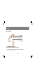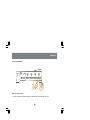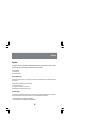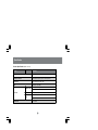
1
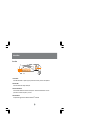
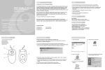
MiniView™ II
4 Port USB KVM Swtich (GCS124U Installation Manual)
©2001 IOGEAR. All Rights Reserved.
IOGEAR, the IOGEAR logo, MiniView, VSE are trademarks or registered trademarks of IOGEAR, Inc. Microsoft and Windows are registered trademarks of
Microsoft Corporation. IBM is a registered trademark of International Business Machines, Inc. Macintosh, G3/G4 and iMac are registered trademarks of
Apple Computer, Inc. IOGEAR makes no warranty of any kind with regards to the information presented in this document. All information furnished here is
for informational purposes only and is subject to change without notice. IOGEAR, Inc. assumes no responsibility for any inaccuracies or errors that may
appear in this document.
Thank you for purchasing one of the most feature-rich keyboard, video, and mouse switches on the market.
IOGEAR’s USB KVM switches are first-rate connectivity accessories designed to help reduce the frustration
of managing multiple computer systems. Wtih the MiniView™ II USB KVM series by IOGEAR, you can
access multiple computers from a single console(keyboard, mouse and monitor). The MiniView™ II USB
KVM provides two convenient methods to access connected computers. Change ports easily via the push
button selection switches located on the unit’s front panel, or by entering Hot Key combinations from the
keyboard or OSD (On Screen Display). Setup is fast and easy; plugging cables into their appropriate ports
is all that is entailed.
We hope you enjoy using your MiniView™ II USB KVM switch, yet another first-rate connectivity solution
from IOGEAR.
Table of Contents
Table of Contents:
Package Contents
02
Overview
03
Features
04
Requirements
06
Introduction
07
Installation
10
Operation
13
Appendix
22
(HotKey)
Specification
24
Radio & TV Interference Statement
26
Limited Warranty
27
Package Contents
This package contains:
1
1
1
4
1
1
MiniViewTM II USB KVM Switch (GCS124U)
User Manual
Registration Card
Premium Bonded USB KVM cables (2-4ft & 2-6ft)
Power Adapter
Quick Start Guide
If any items are damaged or missing please contact your dealer.
2
Overview
Overview
The MiniView™ II USB KVM Switch (GCS124U) is a control unit that allows access to four computers from a
single console (keyboard, mouse and monitor). Before the development of the MiniView II, the only way to
control multiple computer configurations from a single console was through a complex and costly network
system.
Setup is fast and easy, plugging cables into their appropriate posts is all that is entailed. There is no software
to configure, so there is no need to get involved in complex installation routines or be concerned with
incompatibility problems. Since the MiniView™ II intercepts USB keyboard input directly, it works on any
hardware platform and with all operating systems.
The MiniViewTM II USB KVM provides convenient methods to access the computers connected to the USB
KVM system. The MiniViewTM II USB KVM offers push button selection switches located on the units front
panel, Hot Key controls from the USB keyboard, and an On Screen Display (OSD).
There is no better way to save time and money than with a MiniView™ II USB KVM. By allowing a single
console to manage the attached computers, the MiniView™ II USB KVM eliminate the expense of purchasing
a separate keyboard, monitor and mouse. Additionally, it saves space taken up by the additional hardware
and eliminates the inconvenience of switching from the different computer systems.
3
Features
Features
- Premium Bonded USB KVM Cables Included
- Patented VSE (Video Signal Enhancement) Technology for Superior Video Quality
- Patented USB Sniffing Technology
- USB Compatible Mouse Support - Microsoft® Intellimouse Pro & Logitech FirstMouse Support
- Keyboard and Mouse Emulation for Error Free Switching and Booting
- No Delay Between Switching
- Daisy Chainable (control upto 64 USB computers)
- Easy to install - No Software Required
- Computer Selection Via Push Button Switches, Keyboard HotKeys or OSD (On-Screen-Display)
- Auto Scan Function for Monitoring Computer Operation
- Supports up to 1920 x 1440
- LED Display For Easy Status Monitoring
- Easy to Operate
4
Features
Features Continues...
- Unit Can Operate without Power Adapter
- DC Input for External Power Supply
- Hot Swappable
- Rackmountable with optional Rack Mount Kit
- 3 Year Warranty
5
Requirements
Requirements
- USB Enabled Computer
- VGA (or compatible) Type Video Port
MACs: OS 8.6 or greater with latest USB updates
PCs: WIN 98 or greater with USB support
Accessories:
- IOGEAR USB Hub (GUH7144) Expand your USB set up with one of our USB hubs.
- 10’ Bonded USB KVM Cable (G2L1203U), 6’ Bonded USB KVM Cables (G2L1201U)
- Rack Mount Kit for the GCS124U - (G2X007)
• A great add on for rack mounted computer set up
• Size 1U, fits all rack system set ups- 19” Racks
- IOGEAR has a full line of KVM, FireWire, USB, USB 2.0, and ShareView products. Please visit our website at www.iogear.com for further information.
6
Introduction
Introduction on MiniViewTM II USB KVM
The MiniViewTM II GCS124U is a USB KVM switch that controls access to multiple computers from a single console
(keyboard, monitor, and mouse). Before the development of the MiniViewTM II USB KVM, the only way to control multiple
computer configurations from a single console was through a complex and costly network system. Now, with the MiniViewTM II
USB KVM, you can easily access multiple computers in a simple and cost effectively manner.
One MiniViewTM II USB KVM can control up to four PCs. Units can be cascaded to three levels, which means that as many as
21 MiniViewTM II USB KVM units can control up to 64 PCs - all from a single console.
Setup is fast and easy; just plug the cables into their appropriate ports. There is no software to configure so there is no
need to get involved in complex installation routines or be concerned with incompatibility problems. Since the MiniViewTM II
USB KVM accepts keyboard input directly, it works virtually any hardware platform with all operating systems.
The MiniViewTM II USB KVM provides three convenient methods to access any PC connected to the system: (1) using the
port selection buttons on the front panel of each unit; (2) entering Hotkey combinations from the keyboard; and (3) selecting
from on-screen menus through the On Screen Display (OSD) feature. In addition, a powerful Quick View Scan feature allows
you to auto scan and monitor the activities of all operating PCs on the installation one by one.
There is no better way to save time and money than with a MiniViewTM II USB KVM. By allowing the MiniViewTM II USB KVM to
manage all the attached PCs, there is no need to purchase a separate keyboard, monitor, and mouse for each PC, saving an
enormous amount of space. It also eliminates the inconvenience and wasted effort involved in constantly moving around
from one PC to another.
7
Introduction
Front View
4
1
2
3
1. On-Line LEDs
These LEDs indicate that a computer is properly connected to the switch, powered on and operational.
2. Selected LEDs
These LEDs indicate the currently selected port.
3. Port Selection Switches
The Port Selection Switches are located on the front panel. Just below the Selected LEDs. Press the
puch buttons to select the computer of your choice.
4. Auto Scan Switch
This push button toggles Auto Scan Mode for the MiniViewTM II USB KVM.
8
Introduction
Back View
2
2
1
2
1. Power Jack
Port for power adapter
2. Console Port Section
VGA console port for your monitor / USB ports for keyboard, and mouse
3. Console Port Section (USB Port)
USB ports to connect your computer via our premium bonded USB KVM cable
4. Console Port Section (VGA Port)
VGA ports to connect to your computer via our premium bonded USB KVM cables
9
Installation
Setup and Installation
Step.1(Power Adapter / Console Connection)
* Before you begin, please make sure that the power to all devices has been turned off.
1. Plug your USB Mouse, USB Keyboard, and Monitor into the console area on the KVM switch
2. Plug the power adapter into the power adapter port.
10
Installation
Setup and Installation
Step. 2 (Console Connection)
1. Connect the cables that came with the MiniView™ II USB KVM switch to the KVM switch's CPU ports.
11
Installation
Setup and Installation
Step. 3 (Cable Connection)
1. Connect the other end of the cables that came with the MiniView™ II USB KVM switch to your computer.
2. Once complete, turn the USB KVM switch on.
3. Then turn on the power to the connected computers.
12
Operation
Operation
Controlling the computers on your MiniViewTM II USB KVM (GCS124U) from a single console could not be easier. The switch
has three port selection methods providing you with instant access to your computers.
- Manual Port Selection
- HotKey Port Selection
- Daisy Chain Port Selection
Selecting the Active Port
Each CPU port is assigned a numeric ID (1-4). You can directly access any computer connected to the KVM with a hotkey combination that specifies the
ID of the CPU port.
Press and release each of the following keys, in order, until complete
• [control] Press the control key once
• [1, 2, 3, 4] Enter the number of the port you wish to switch to.
• [ENTER] Pressing enter completes the port selection process
Forward/Back mode
This feature allows you to switch between computers in order to monitor them manually. You can dwell on a particular post for as long or as little as you
like as opposed to Auto Scan Mode, which switches after a fixed interval. To invoke Last/Next Mode, press the following keys.
1. Press and release [F1] twice to move Back through the USB KVM Ports
2. Press and release [F4] twice to move FORWARD through the USB KVM Ports
13
Operation
Operation cont.
Once scanning begins it will continue until you press the spacebar or the round button on the front of the USB KVM. The
port last seen during the scan will become the active port.
NOTE: While Auto Scan Mode is in effect none of the basic keyboard keys will function until you end the auto scan.
OSD Overview
On Screen Display (OSD) provides a menu driven interface to handle PC switching Procedures. All operations start from the OSD Main Screen. To
activate the OSD, Tap the CTRL key twice, [ctrl][ctrl].
NOTE: If using the control key conflicts with applications running on any of the Computers, you can change the OSD Activation Hotkey to [Scroll Lock]
[Scroll Lock].
The OSD always starts in LIST view with the Highlight bar at the same position it was in the last time it was closed.
The Port Number (PN) for each computer is shown in the left most column on the list. You can directly access any port by using Navigation keys to move
the Highlight bar to the desired port and press [ENTER].
The computers port number is derived from the CPU port (1-4) on the GCS124U back panel that the computer is connected to. For example to access a
computer connected to port 3 you would move up or down the list with the arrow keys and press enter once port 3 is highlighted. Remember: The port
number for a computer connected to a daisy chained GCS124U is a 2 digit number. The first digit represents the CPU Port number of the primary USB
KVM and the second digit represents the CPU Port number of the secondary USB KVM that the computer is connected to. For example to access a
computer connected to CPU Port 3 of the secondary USB KVM, scroll down the list and press enter on 2-3.
14
Operation
Navigation:
To exit from the OSD menu at any thime press [ESC]
Use the Up and Down arrow keys to move through the list one line at a time
Use [PG UP] and [PG DOWN] to move up or down through the list, one screen at a time
To activate a port move the Highlight Bar to the desired port and press [ENTER]
Function Keys:
With the OSD activated, pressing a function key (F1-F6) brings up a related sub menu that is used to configure and control
the OSD.
F1 GOTO: After pressing F1 select the desired port number or port name and press [ENTER]. Your monitor will now display the selected computer.
15
Operation
F2 SCAN:
OSD Operation
Pressing F2 initiates the Scan Mode in which the KVM cycles through all the ports that have been selected for scanning within the List settings (F3). When
you want to stop at a particular location or stop the scanning process simply press the [spacebar] or the round button on the from of the USB KVM.
NOTE:
1. If the scanning stops on an empty port or one where the computer is powered off the monitor screeen will be blank and the
mouse and keyboard will have no effect. To recover activate the OSD and choose any powered on or Functioning computer.
2. As the OSD cycles through the selected ports an S Appears in front of the Port ID display as each comptuer is accessed to
indicate that the computer is being accesed under QUICK VIEW scanning
3. If a particular port has not been selected in the list menu (See F3 List) the scan will not display that computer
F3 LIST:
This function brings up a submenu that lets you broaden or narrow the scope of which ports the OSD lists. This will be different for each console depending
on the choices made for that console. The choices and their meanings are given in the Table below:
To make a choice, move the highlihgt bar to the desired selection and press [ENTER]. An icon will appear before the selected line to indicate that it is
currently selected.
NOTE:
1. You can access any port on any list by using the Navigation Keys then Pressing [ENTER].
2. If you select a port that does not have a computer attached to it, or if the attached computer is powered off, the OSD will still switch to it showing a blank
scren.
16
Operation
F4 QV (quick view):
OSD Operation
You can broaden or narrow the number of ports that get automatically scanned by selecting only the ones you want within this menu. To select/deselect a port
for Quick View:
1. Use the up and down arrow keys to move the highlight bar to the desired port.
2. Press F4
When a port has been selectedfor Quick View scanning an arrowhead displays in the FQ Column. When a port is deselected the arrowhead will disappear.
F5 EDIT:
Here you can name each of your ports allowing yo to easily identify each connected computer.
1. Use the navigation key to move the highlight bar to the port you want.
2. Press F5
3. Key in the new port name or modify/delete the old one.
The maximum number of characters allowed for a port name is 15 Legal Characters include
All alpha characters a-z; A-Z
All numeric charaters 0-9
Any of the following (-)(:)(.)(Space)
The OSD is not case sensitive so it will not matter if the OSD displays the port name in all capitals or other. When you finish editing, press [ENTER] to have
the change take effect. To abort the change Press ESC.
17
Operation
F6 SET:
When you press F6 a submenu appears that allows you to configure the OSD settings for the console you are working at. To change the settings use the up
and down keys to move the highlight bar to the desired menu item and press [ENTER].
If a sub menu has further choices to select from move the highlight bar to the desired menu option and press [ENTER].
Refer to the table below for menu / submenu navigation.
18
Operation
Daisy Chaining:
The Conection
What You Need:
One (1) of the following cables for each additional USB KVM added (6ft G2L1201U or 10ft G2L1203U).
One (1) additional GCS124U for each new daisy chain level.
Daisy Chaining the GCS124U is very simple. Simply purchase a second unit (up to 3 additional units/levels deep) and a USB
KVM cable and connect the 2nd USB KVM’s console port on the primary USB KVM.
19
Operation
Daisy Chain Port Selection:
Each CPU port is assigned a numeric ID (1-4). Each daisy chained MiniViewTM II USB KVM is also assigned a numeric ID
(1-4). You can directly access any computer connected to the KVM and each additional daisy chained KVM with a hotkey
combination that specifies the ID of the CPU port and the ID ofthe daisy chained CPU port.
The idea behind selecting computer through daisy chained KVMs is to select the KVM CPU port that the daisy chained KVM is
attached. Once that port is selected you can select the port of the ocmputer you wish to access. The key commands are as
folows:
Press and release each of the following keys, in order, until complete.
• [control] Press the control key once
• [1, 2, 3, 4] Enter the number of the port that the daisy-chained computer is connected.
• [1, 2, 3, 4] Enter the number of the daisy-chained KVMs port you wish to switch to.
• [ENTER] Pressing enter completes the port selection process.
20
Operation
A typical daisy chain set up and command sequence may look llike the following.
You have 7 USB computers. 3 of the computers are connected to the primary USB KVM. A secondary USB KVM is connected
to port 4 on the first USB KVM. The additional 4 computers are then connected to the Secondary USB KVM>
If I wanted to view and use computer number 6 I would use the following key sequence:
[control]+[4]+[3]+[ENTER]
Now you try... ;-)
21
Appendix
HotKey Commands (Model: GCS124U)
Combination
Acti on
[Ctrl]+[Ctrl]
Opens OSD Menu
or [scroll lock] + [scroll lock]
[ctrl]+[1 or 2 or 3 or 4] + [Enter]
To select desired port
Humidity
Toggle backward through ports
Housing
Toggle forward through ports
Weight
To activate auto scan
22
Appendix
Troubleshooting (Model: GCS124U)
Note: If the unit appears to be operating erracticallly, check all cables for damage and to be sure that they are properly connected. If you are operating
under nonpowered mode, use the external power adapter.
If you need further assistance please check out our IOGEAR Tech Info Library (T.I.L.) at www.iogear.com/support for the latest tips, tricks, and troubleshooting. The IOGEAR T.I.L. was designed to provide you with the latest technical information about our products. Most of the answers to your questions can be
found here, so please try it out before contacting technical support.
Technical Support is available Monday through Friday from 8:00am to 5:00pm PST and can be reached at 949-428-1111.
23
Specification
Product Specification
(MODEL: GCS124)
Function
Specification
Power Consumption
DC 9V, 600mA
Computer Connections
4 USB enabled computers (up to 64 when daisychained)
Port Selection
Push button Switches; Hotkeys, OSD
LEDs
4 (Green) & 4 (neon Blue)
1 USB Keyboard Port (type A) - Console
USB type A Port
1 USB Mouse Port (type A) - Console
Connectors
USB type B Port
4 USB type B ports (Mouse and Keyboard shared port) - Computer
1 VGA (HD15F) Port - Console
Video
4 VGA (HD15M) Ports - Computer
Scan Intervals
5 & 15 Second
24
Specification
Function
Specification
Resolution
1920 x 1440
Operating Temp
5° ~ 40°C
Storage Temp
-20° ~ 40°C
Humidity
0 - 80% RH
Housi ng
Metal
Weight
2.9 lb
Dimension (LxWxH)
8.8 x 6.0 x 2.0 in
25
Radio & TV Interference Statement
Radio & TV Interference Statement
WARNING!!! This equipment generates, uses and can radiate radio frequency energy and, if not installed and
used in accordance with the instruction manual, may cause interference to radio communications. This
equipment has been tested and found to comply with the limits for a Class B computing device pursuant to
Subpart J of Part 15 of FCC Rules, which are designed to provide reasonable protection against such
interference when operated in a commercial environment. Operation of this equipment in a residential area is
likely to cause interference, in which case the user at his own expense will be required to take whatever
measures may be required to correct the interference.
26
Limited Warranty
Limited Warranty
IN NO EVENT SHALL THE DIRECT VENDOR’S LIABILITY FOR DIRECT, INDIRECT, SPECIAL, INCIDENTAL OR CONSEQUENTIAL DAMAGES RESULTING FROM THE USE OF THE PRODUCT, DIST ORITS
DOCUMENTATION EXCEED THE PRICE PAID FOR THE PRODUCT.
The direct vendor makes no warranty or representation, expressed, implied, or statutory with respect to the
contents or use of this documentation, and especially disclaims its quality, performance, merchantability, or
fitness for any particular purpose.
The direct vendor also reserves the right to revise or update the device or documentation without obligation to
notify any individual or entity of such revisions, or updates. For further inquires please contact your direct
vendor.
27
Contact info.
23 Hubble Drive
•
Irvine, CA 92618
•
(P) 949.428.1111
•
(F) 949.428.1100
•
www.iogear.com