1
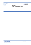
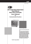
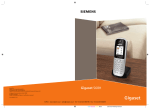
APPLICATION SPECIFICATION
STAC64 SYSTEM APPLICATION GUIDE
1.0 SCOPE THIS INSTRUCTION MANUAL CONTAINS SUPPLEMENTAL INFORMATION PERTAINING
TO THE MOLEX STAC64 UNSEALED DUAL ROW 0.64 SERIES 34729, STAC64 UNSEALED DUAL
ROW HYBRID 2.8-1.5 SERIES 31372, AND THE STAC64 HEADERS SERIES 34690, 34691
Table of Contents
Section 1: Product Introduction
Section 2: Product Summary
Section 3: Connector Assembly
Section 4: Connector Mating
Section 5: Service Instructions
REVISION:
A
ECR/ECN INFORMATION:
EC No: UAU2010-1892
TITLE:
SHEET No.
STAC64 SYSTEM APPLICATION GUIDE
DATE: 2010 / 7 / 22
DOCUMENT NUMBER:
AS-34729-020
CREATED / REVISED BY:
Chris Taylor
CHECKED BY:
Brad Dick
1 of 15
APPROVED BY:
Chris Dillon
TEMPLATE FILENAME: APPLICATION_SPEC[SIZE_A](V.1).DOC
APPLICATION SPECIFICATION
2.0 PRODUCT DESCRIPTION
34690 Single Bay Vertical Headers
34691 Single Bay Right Angle
34695 Single Bay Hybrid Vertical Headers
34696 Single Bay Hybrid Right Angle Headers
34707 Ganged Multi-Bay Vertical Headers
34708 Ganged Multi-Bay Right Angle Headers
34729 8-20 Circuit Receptacle Connectors
31372 10 Circuit Hybrid Receptacle Assembly
34803 CTX64 Female Receptacle Terminals
33012 MX150 Female Receptacle Terminals
REVISION:
A
ECR/ECN INFORMATION:
EC No: UAU2010-1892
TITLE:
SHEET No.
STAC64 SYSTEM APPLICATION GUIDE
DATE: 2010 / 7 / 22
DOCUMENT NUMBER:
AS-34729-020
CREATED / REVISED BY:
Chris Taylor
CHECKED BY:
Brad Dick
2 of 15
APPROVED BY:
Chris Dillon
TEMPLATE FILENAME: APPLICATION_SPEC[SIZE_A](V.1).DOC
APPLICATION SPECIFICATION
3.0 REFERENCE DOCUMENTS SD 34729-020, PK 31301-201, AND PS-34729-020. SD-34690-100, SD34691-100, SD-34695-100, SD-34696-100, SD-31372-900, PS-31372-100, PK-31372-931, PS-34691-100, PS34696-100
REVISION:
A
ECR/ECN INFORMATION:
EC No: UAU2010-1892
TITLE:
SHEET No.
STAC64 SYSTEM APPLICATION GUIDE
DATE: 2010 / 7 / 22
DOCUMENT NUMBER:
AS-34729-020
CREATED / REVISED BY:
Chris Taylor
CHECKED BY:
Brad Dick
3 of 15
APPROVED BY:
Chris Dillon
TEMPLATE FILENAME: APPLICATION_SPEC[SIZE_A](V.1).DOC
APPLICATION SPECIFICATION
A. Connectors shown in “As Shipped”
Connector TPA shown in “as shipped” condition (pre-lock). The TPA must remain in the
pre-lock position until all circuits are loaded.
B. TPA “lift to pre-lock”
TPA must be in pre-lock position to populate the connector. If during shipping the Connector
TPA moves from it’s pre-lock position. Simply squeeze both sides of the TPA and slide it
up the TPA will snap into pre-lock position.
If the TPA or housing is damaged in any way do not use the connector!!!
Squeeze
Squeeze & Slide
Click TPA in Pre-lock
B.(continued)TPA “lift to pre-lock” HYBRID
TPA must be in pre-lock position to populate the connector. Slide a small screwdriver
Under the edge of the TPA on one side. Using the blade of the screwdriver gently push TPA
upwards. Repeat this on the opposite side, TPA will snap into pre-lock position.
If the TPA or housing is damaged in any way do not use the connector!!!
TPA in Pre-lock
REVISION:
A
ECR/ECN INFORMATION:
EC No: UAU2010-1892
TITLE:
SHEET No.
STAC64 SYSTEM APPLICATION GUIDE
DATE: 2010 / 7 / 22
DOCUMENT NUMBER:
AS-34729-020
CREATED / REVISED BY:
Chris Taylor
CHECKED BY:
Brad Dick
4 of 15
APPROVED BY:
Chris Dillon
TEMPLATE FILENAME: APPLICATION_SPEC[SIZE_A](V.1).DOC
APPLICATION SPECIFICATION
C.
Terminal Installation:
With TPA still in pre-lock position, orient terminal to rear of connector as shown below.
Grip the wire no less than 1.25 inches from the terminal insulation crimp and insert
through appropriate circuit opening. If resistance is encountered, retract the terminal and
adjust the angle of insertion. Continue inserting the terminal until it stops and locks up
on the lock finger with an audible click.
PUSH
CLICK
PULL
TPA must be in Pre-Lock Position to Populate Connector
C.
(continued) Terminal Installation: 1.5mm terminals is the same as above
CLICK
PUSH
PULL
TPA must be in Pre-Lock Position to Populate Connector
C. (continued) Terminal Installation: for 2.8 terminals is the same as above.
2.8mm terminal
PUSH
REVISION:
A
ECR/ECN INFORMATION:
EC No: UAU2010-1892
PULL
CLICK
TITLE:
SHEET No.
STAC64 SYSTEM APPLICATION GUIDE
DATE: 2010 / 7 / 22
DOCUMENT NUMBER:
AS-34729-020
CREATED / REVISED BY:
Chris Taylor
CHECKED BY:
Brad Dick
5 of 15
APPROVED BY:
Chris Dillon
TEMPLATE FILENAME: APPLICATION_SPEC[SIZE_A](V.1).DOC
APPLICATION SPECIFICATION
D. Seating the TPA
With the receptacle terminals fully installed, the TPA can be seated into its final lock position
by squeezing both sides of the TPA evenly, then sliding the TPA toward the housing until it
comes to a stop flush to the top of the connector housing.
Push uniformly on TPA sides to fully seat.
D. Seating the TPA HYBRID Connector
With the receptacle terminals fully installed, the TPA can be seated into its final lock position
by applying an even force to the TPA surface until it comes to a stop, with an audible click.
Push uniformly on TPA main surface only to fully seat.
CLICK
REVISION:
A
ECR/ECN INFORMATION:
EC No: UAU2010-1892
TITLE:
SHEET No.
STAC64 SYSTEM APPLICATION GUIDE
DATE: 2010 / 7 / 22
DOCUMENT NUMBER:
AS-34729-020
CREATED / REVISED BY:
Chris Taylor
CHECKED BY:
Brad Dick
6 of 15
APPROVED BY:
Chris Dillon
TEMPLATE FILENAME: APPLICATION_SPEC[SIZE_A](V.1).DOC
APPLICATION SPECIFICATION
A.
Connector Mating
Note and align connector keying features, from receptacle connector to Mating header.
Keying features
B. Begin mating procedure by sliding the receptacle connector assembly into the header
assembly, press firmly until you hear an audible click.
PUSH
A.
CLICK
PULL
Connector Mating HYBRID Connector
Note and align connector keying features, from receptacle connector to Mating header.
Keying features
B. Begin mating procedure by sliding the receptacle connector assembly into the header
assembly, press firmly until you hear an audible click.
PUSH
REVISION:
A
ECR/ECN INFORMATION:
EC No: UAU2010-1892
CLICK
PULL
TITLE:
SHEET No.
STAC64 SYSTEM APPLICATION GUIDE
DATE: 2010 / 7 / 22
DOCUMENT NUMBER:
AS-34729-020
CREATED / REVISED BY:
Chris Taylor
CHECKED BY:
Brad Dick
7 of 15
APPROVED BY:
Chris Dillon
TEMPLATE FILENAME: APPLICATION_SPEC[SIZE_A](V.1).DOC
APPLICATION SPECIFICATION
A. Terminal servicing
Squeeze and slide the TPA away from the housing. TPA will snap into the pre-lock position.
With the TPA in pre-lock use the designated service tool, push through the service hole to
disengage the lock finger. Push straight until reaching a hard stop. Once the Lock finger is
disengaged, gently pull on the wire to release the terminal.
Squeeze and slide
TPA in pre-lock
Servicing terminal
REVISION:
A
ECR/ECN INFORMATION:
EC No: UAU2010-1892
TITLE:
SHEET No.
STAC64 SYSTEM APPLICATION GUIDE
DATE: 2010 / 7 / 22
DOCUMENT NUMBER:
AS-34729-020
CREATED / REVISED BY:
Chris Taylor
CHECKED BY:
Brad Dick
8 of 15
APPROVED BY:
Chris Dillon
TEMPLATE FILENAME: APPLICATION_SPEC[SIZE_A](V.1).DOC
APPLICATION SPECIFICATION
A. Terminal servicing HYBRID
Slide small screwdriver under the edge of the TPA on one side. Then using the blade of
screwdriver, gently push TPA upwards. Repeat step 1 on opposite side.. TPA will snap into the
pre-lock position.
Step 1
A.
TPA in pre-lock
Terminal servicing (continued)
With the TPA in pre-lock use the designated service tool Molex P/N 63813-1500,
push through the service hole to disengage the lock finger. Push straight until
reaching a hard stop. Once the Lock finger is disengaged, gently pull on the wire to
release the terminal.
Service holes
1.5mm
REVISION:
A
ECR/ECN INFORMATION:
EC No: UAU2010-1892
2.8mm
TITLE:
SHEET No.
STAC64 SYSTEM APPLICATION GUIDE
DATE: 2010 / 7 / 22
DOCUMENT NUMBER:
AS-34729-020
CREATED / REVISED BY:
Chris Taylor
CHECKED BY:
Brad Dick
9 of 15
APPROVED BY:
Chris Dillon
TEMPLATE FILENAME: APPLICATION_SPEC[SIZE_A](V.1).DOC
APPLICATION SPECIFICATION
B. Electrical probing, continuity checking
The preferred method of probing; use the Probe opening for receptacle terminal to
check for electrical continuity.
C. Electrical continuity check list
Never probe in terminal contact area
Use the designated access point.
Probe pin recommendations:
1.When testing the connector for continuity it is imperative that you do not damage the
terminals!
2.Pogo pins should be checked for damage or sticking several times a shift. This should
assure containment if an issue is found.
3.First a visual inspection of all the pins for damage should be performed.
4.Next a testing block should be used to depress all the pogo pins up into the barrel. If there
is a bent or sticking pin, it should remain stuck in the barrel of the pogo pin. A
damaged or stuck pin should be replaced before any additional testing is performed.
Probing damage can occur:
1.If a sharp ended probe is inserted into the contact of the terminal it may damage the plating
and increase contact resistance
2.If an oversized diameter probe is inserted into the terminal, this will overstress the beam in
the terminal. This will create an environment for intermittent connections, and
increased contact resistance.
3.If a probe is inserted into the connector on an angle or off center it may damage the
terminal, and or the connector.
REVISION:
A
ECR/ECN INFORMATION:
EC No: UAU2010-1892
TITLE:
SHEET No.
STAC64 SYSTEM APPLICATION GUIDE
DATE: 2010 / 7 / 22
DOCUMENT NUMBER:
AS-34729-020
CREATED / REVISED BY:
Chris Taylor
CHECKED BY:
Brad Dick
10 of 15
APPROVED BY:
Chris Dillon
TEMPLATE FILENAME: APPLICATION_SPEC[SIZE_A](V.1).DOC
APPLICATION SPECIFICATION
4.0 PROCEDURE
4.1 GENERAL REQUIREMENTS: PLEASE SEE PK-31300-892, FOR PRODUCT SPECIFIATIONS.
4.2 ASSEMBLY INSTRUCTIONS:
WHERE FORCE NEEDS TO BE APPLIED TO SEAT HEADER TO PCB (PRESS FIT, OUTER
POSTS)
NOTE: ANY PRESSURE PLACED ON THE HEADER PINS MAY DAMAGE THE ASSEMBLY
REVISION:
A
ECR/ECN INFORMATION:
EC No: UAU2010-1892
TITLE:
SHEET No.
STAC64 SYSTEM APPLICATION GUIDE
DATE: 2010 / 7 / 22
DOCUMENT NUMBER:
AS-34729-020
CREATED / REVISED BY:
Chris Taylor
CHECKED BY:
Brad Dick
11 of 15
APPROVED BY:
Chris Dillon
TEMPLATE FILENAME: APPLICATION_SPEC[SIZE_A](V.1).DOC
APPLICATION SPECIFICATION
4.3 DRAWING DETAIL:
BELOW ARE VIEWS FROM THE 2 BAY STAC’D HEADER DRAWING. ALL 2 BAY HEADERS
WILL BE COVERED BY THIS SINGLE DRAWING.
WHEN LOOKING AT THE FRONT (MATE) SIDE OF THE HEADER IT CAN BE DETERMINED
WHAT HEADER BAY’S ARE IN WHAT LOCATIONS. THE BAY LETTER REFERENCES (BAY
‘A’, BAY ‘B’, ECT.) ARE LOCATIONS ONLY AND DO NOT REPRESENT ANY PARTICULAR
CIRCUIT SIZE OR KEY OPTION.
THE HEADER ‘BAY ID’ SECTION ON THE CHART CORRESPONDS WITH THE LOCATION ON
THE FRONT VIEW OF THE HEADER.
REVISION:
A
ECR/ECN INFORMATION:
EC No: UAU2010-1892
TITLE:
SHEET No.
STAC64 SYSTEM APPLICATION GUIDE
DATE: 2010 / 7 / 22
DOCUMENT NUMBER:
AS-34729-020
CREATED / REVISED BY:
Chris Taylor
CHECKED BY:
Brad Dick
12 of 15
APPROVED BY:
Chris Dillon
TEMPLATE FILENAME: APPLICATION_SPEC[SIZE_A](V.1).DOC
APPLICATION SPECIFICATION
RECOMMENDED HEADER MOUNTING STRATEGIES (RIGHT ANGLE HEADER ONLY):
TYPE 2
TYPE 1
TYPE 1:
THE BOTTOM STANDOFF RIBS ARE NOT USED. THE HEADER(S) RESTS FLAT ON
THE PCB.
TYPE 2:
THE RIBS ON THE BOTTOM OF THE PART(S) REST ON THE PCB ALLOWING FOR
SOLDER JOINT INSPECTION AFTER SOLDERING.
BUILDING OF A PRINTED CIRCUIT BOARD LAYOUT:
NOTE: THE SAME BAY ID MUST BE USED FROM THE CHART ON PAGE 1.
1. REFERENCE CHART ON PAGE 1 FOR WHAT CIRCUIT
SIZE AND TYPE OF HEADER GO IN EACH ‘BAY’ LOCATION.
2. DETERMINE IF HEADER MUST BE DROP IN CAPABLE
OR IF PRESS FIT IS ACCEPTABLE. PRESS FIT IS RECOMMENDED
AND WILL RETAIN HEADER DURING PROCESSING.
REVISION:
A
ECR/ECN INFORMATION:
EC No: UAU2010-1892
TITLE:
SHEET No.
STAC64 SYSTEM APPLICATION GUIDE
DATE: 2010 / 7 / 22
DOCUMENT NUMBER:
AS-34729-020
CREATED / REVISED BY:
Chris Taylor
CHECKED BY:
Brad Dick
13 of 15
APPROVED BY:
Chris Dillon
TEMPLATE FILENAME: APPLICATION_SPEC[SIZE_A](V.1).DOC
APPLICATION SPECIFICATION
3. USING THE SINGLE HEADER LAYOUTS BELOW BUILD THE PCB LAYOUT OF THE MULTI-BAY
HEADER BY SPACING ADJACENT POST HOLES AT 4.96mm.
KEEP OUT AREAS (RIGHT ANGLE HEADERS)
4. PLACE NECESSARY PCB LAYOUT IN
EACH ‘BAY’ LOCATION AT 4.96mm SPACING.
80CKT – 4 BAY HEADER FOOT PRINT – 20X20X20X20
REVISION:
A
ECR/ECN INFORMATION:
EC No: UAU2010-1892
TITLE:
SHEET No.
STAC64 SYSTEM APPLICATION GUIDE
DATE: 2010 / 7 / 22
DOCUMENT NUMBER:
AS-34729-020
CREATED / REVISED BY:
Chris Taylor
CHECKED BY:
Brad Dick
14 of 15
APPROVED BY:
Chris Dillon
TEMPLATE FILENAME: APPLICATION_SPEC[SIZE_A](V.1).DOC
APPLICATION SPECIFICATION
5.0 PROCEDURE
4.4 GENERAL REQUIREMENTS
4.5 ASSEMBLY INSTRUCTIONS
4.6 REMOVAL INSTRUCTIONS
REVISION:
A
ECR/ECN INFORMATION:
EC No: UAU2010-1892
TITLE:
SHEET No.
STAC64 SYSTEM APPLICATION GUIDE
DATE: 2010 / 7 / 22
DOCUMENT NUMBER:
AS-34729-020
CREATED / REVISED BY:
Chris Taylor
CHECKED BY:
Brad Dick
15 of 15
APPROVED BY:
Chris Dillon
TEMPLATE FILENAME: APPLICATION_SPEC[SIZE_A](V.1).DOC