1
Simul_Hexapod
Hexapod Control
Simulation Software
User’s Manual
For Motion, Think Newport
Simul_Hexapod
Hexapod Control Simulation Software
Preface
Confidentiality & Proprietary Rights
Reservation of Title
The Newport Programs and all materials furnished or produced in connection with them
("Related Materials") contain trade secrets of Newport and are for use only in the
manner expressly permitted. Newport claims and reserves all rights and benefits
afforded under law in the Programs provided by Newport Corporation.
Newport shall retain full ownership of Intellectual Property Rights in and to all
development, process, align or assembly technologies developed and other derivative
work that may be developed by Newport. Customer shall not challenge, or cause any
third party to challenge, the rights of Newport.
Preservation of Secrecy and Confidentiality and Restrictions to Access
Customer shall protect the Newport Programs and Related Materials as trade secrets of
Newport, and shall devote its best efforts to ensure that all its personnel protect the
Newport Programs as trade secrets of Newport Corporation. Customer shall not at any
time disclose Newport's trade secrets to any other person, firm, organization, or
employee that does not need (consistent with Customer's right of use hereunder) to
obtain access to the Newport Programs and Related Materials. These restrictions shall
not apply to information (1) generally known to the public or obtainable from public
sources; (2) readily apparent from the keyboard operations, visual display, or output
reports of the Programs; (3) previously in the possession of Customer or subsequently
developed or acquired without reliance on the Newport Programs; or (4) approved by
Newport for release without restriction.
©2011 Newport Corporation
1791 Deere Ave.
Irvine, CA 92606, USA
(949) 863-3144
EDH0313En1010 – 12/11
ii
Simul_Hexapod
Hexapod Control Simulation Software
Table of Contents
Preface ..............................................................................................................................ii
Confidentiality & Proprietary Rights...............................................................ii
1.0
Simul_Hexapod Windows Description ....................................................... 1
2.0
Newport Hexapod Conventions................................................................... 2
3.0
Simul-Hexapod Software Installation......................................................... 5
4.0
Starting Simul-Hexapod .............................................................................. 6
5.0
Using Simul-Hexapod................................................................................... 7
5.1
Virtual Hexapod Display .........................................................................................................7
5.2
5.1.1
Virtual hexapod conventions ...............................................................................7
5.1.2
Mouse control and features ..................................................................................7
Main Menu ..............................................................................................................................8
5.2.1
File .......................................................................................................................8
5.2.2
Setup menu ..........................................................................................................8
5.2.3
About Menu .......................................................................................................11
5.3
Setting the Hexapod’s Coordinates........................................................................................12
5.4
Hexapod Displacement Control.............................................................................................13
5.4.1
Absolute positioning in Work coordinates.........................................................13
5.4.2
Relative positioning in Work coordinates..........................................................13
5.4.3
Relative positioning in Tool coordinates ...........................................................15
5.4.4
Actuator Positioning ..........................................................................................15
iii
EDH0313En1010 – 12/11
Simul_Hexapod
EDH0313En1010 – 12/11
Hexapod Control Simulation Software
iv
Simul_Hexapod
Hexapod Control Simulation Software
Simul_Hexapod
Hexapod Control Simulation Software
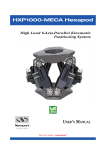
1.0
Simul_Hexapod Windows Description
Simul_Hexapod software includes 3 main windows:
A Virtual Hexapod display window
A Manual Control window
A reference setting window
The Manual control window can be displayed or hidden by checking the “Manual
Control” Box located at the bottom right of the Virtual hexapod display window.
Virtual hexapod display
Coordinates
Main menu
Manual Control
EDH0313En1010 – 12/11
Manual Control
Virtual hexapod Display Area
Exit Button
Joystick Control Area
1
Hexapod Actuators Position
Coordinate Setting
Simul_Hexapod
2.0
Hexapod Control Simulation Software
Newport Hexapod Conventions
Hexapod is used to move an object relatively to another:
Fixed Reference
Attached to the base
“Work”
Moving Object
Attached to the carriage
“Tool”
Position and orientation of fixed object (Work) and moving object (Tool) are
defined by coordinates systems linked to them:
“Work”
Coordinate System
“Tool”
Coordinate System
EDH0313En1010 – 12/11
2
Simul_Hexapod
Hexapod Control Simulation Software
Work & Tool coordinates system have to be defined
relatively to the Hexapod:
(Configuration saved in HXP system.ini file)
“Work”
Coordinate System
“Tool”
Coordinate System
Work and Base are
defined relative to a
reference called World
Tool is define relative
to Carriage
“World” = Reference
Hexapod Position (X,Y,Z,U,V,W) = Position & Orientation of Tool in Work:
Zw
“Work”
Coordinate System
Zt
Xw
Yw
“Tool”
Coordinate System
Y
Yt
Xt
X, Y, Z = Coordinates of the origin of Tool in Xw, Yw, Zw
U, V, W = Orientation of Xt, Yt, Zt directions relative to Xw,Yw,Zw directions (Bryant Angles)
Hexapod Absolute Move = Motion to Hexapod Absolute Position
3
EDH0313En1010 – 12/11
Simul_Hexapod
Hexapod Control Simulation Software
Orientation U, V, W = Bryant angles :
– Clockwise rotation about the Z-axis by
the Yaw angle W
– Clockwise rotation about the New Y-axis
“Y” by the Pitch angle V
– Clockwise rotation about the new X-axis
“X” by the Roll angle U
Hexapod construction parameter definitions:
The schematic below describes the standard conventions (actuator number, axes
definitions, and planes) of Newport hexapods.
Z
Carriage Diameter
Carriage Alpha
x
Carriage Thickness
Y
Actuator Length at Home Preset
Z
4
5
Base Diameter
Base Thickness
6
x
3
2
1
120°
Base Alpha
NOTE
Black points represent the theoretical positions of the twelve joints of a hexapod.
Plain circular lines represent the hexapod planes (passing through the joints) and
dotted circular lines represent the hexapod reference planes (upper side of the
carriage and lower side of the base)
Newport Hexapod HPX 100 dimensions:
– Base and Carriage thickness: 25 mm
– Actuator length: 166 to 192 mm
– Distance between the reference planes of the joints when actuators are at
166 mm: 144, 23 mm
EDH0313En1010 – 12/11
4
Simul_Hexapod
3.0
Hexapod Control Simulation Software
Simul-Hexapod Software Installation
Insert the Simul_Hexapod CD into your CD or DVD-ROM drive. Proceed as follows:
Click Start on the Windows taskbar
Select Run from the Start menu
Click Browse and locate your CD or DVD-ROM drive to view the files in the CD
Find the installer program named SETUP.EXE and double click this file, then click
OK in the Run dialog
Follow on-screen instructions to install Simul_Hexapod software.
The following directories will be automatically created:
C:/…/Simul_Hexapod: containing following files
– Simul_hexapod.exe
– Simul_hexapod.exe-shortcut
– Simul_hexapod.ini
– Simul_hexapod_LANGUAGE_1.ini
– Simul_hexapod_LANGUAGE_2.ini
C:/…/Simul_Hexapod/CFG: containing following files
– HXP100.CFG
– HXP1000.CFG
In the “C:/…/Simul_Hexapod “ directory, click and drag the “simul_hexapod.exeshortcut” to your desktop.
5
EDH0313En1010 – 12/11
Simul_Hexapod
4.0
Hexapod Control Simulation Software
Starting Simul-Hexapod
On your desktop, double-click on “simul_hexapod.exe-shortcut.
A message appears prompting the user to select the hexapod configuration to be loaded.
A pull-down list displays the available configurations.
NOTE
Newport standard hexapods (HXP100, HXP1000, etc.) are default. Other
configurations can be defined and saved by the user. (See Save Current
Configuration chapter)
Click “OK” to launch Simul-Hexapod with the selected configuration.
NOTE
If not selection is made within 20 seconds, the last saved configuration will be
automatically loaded.
EDH0313En1010 – 12/11
6
Simul_Hexapod
5.0
Hexapod Control Simulation Software
Using Simul-Hexapod
The main window opens up and displays the virtual Hexapod using parameters from the
selected configuration file. (Window Size, position, Hexapod size, position, orientation,
etc…).
The manual control window may also be displayed if it was enabled in the configuration
file.
The user can perform the following actions:
Set the Virtual hexapod display parameters
Access Main menu functions
Set Coordinates origin point
Move the virtual hexapod
5.1
Virtual Hexapod Display
The virtual hexapod is displayed and can be
controlled as described below:
5.1.1
Virtual hexapod conventions
Axes colors : X: Red, Y: Green, Z: Blue ,
U (Rx): around Red axis, V (Ry): around
Green axis, W (Rz): around Blue axis
Red point :
The Tool Coordinate
System's origin is defined in the “Hexapod
Coordinates Setting” window, “Tool to
Carriage” panel
The Work Coordinate
Blue point :
System's origin is defined in XYZ in the
“Hexapod Coordinates Setting” window,
“Work to Base” panel
5.1.2
Mouse control and features
Mouse scroll up or down (anywhere in the
screen): zoom in or out
Mouse left click (anywhere) and drag: rotates
the virtual hexapod (2 directions)
Mouse left double-click on a point: re-center
this point in the screen
Mouse right click (anywhere) and drag:
moves the virtual hexapod left/right-Up/down
Mouse right click (anywhere) and release:
displays the menu:
– X<->Y, X<->Z or Y<->Z : click one for a
2D view of the hexapod.
– “Center on 0,0,0”: places the Hexapod
Base (0,0,0 world coordinates) in center
of the screen
7
EDH0313En1010 – 12/11
Simul_Hexapod
Hexapod Control Simulation Software
5.2
Main Menu
5.2.1
File
This menu allows:
Text files Editing through a text editor
Exiting Simul-Hexapod software
5.2.2
Setup menu
This menu allows setting all Simul-Hexapod software parameters using 5 commands:
5.2.2.1
Hexapod
This sub-menu opens up a window to set all mechanical parameters (HXP100
parameters, as an example):
Work to Base panel:
to define the Work Coordinate origin location (X, Y &Z,
relative to the Base centre).
Tool to Carriage panel:
to define the Tool coordinate origin location (X, Y &Z,
relative to the Carriage centre).
NOTE
These settings are also accessible through the Hexapod Coordinates Setting
window.
Height:
Distance between joints reference planes when actuators are
at their minimum position
Carriage panel:
to define the positions of the carriage end of the actuator
joints
Base panel:
to define the positions of the base end actuator joints
positions
NOTE
Joint positions can be defined using XY or polar coordinates. (In case of Polar
coordinates, the “Calculate” button must be pressed after entering angles to
update the XY coordinates
Actuators panel:
EDH0313En1010 – 12/11
to define the actuators’ length and travel range
8
Simul_Hexapod
Hexapod Control Simulation Software
5.2.2.2
Display
This sub-menu allows setting of the following parameters:
Number of digits displayed in the
“Actuators position” panel of the
Manual control window
NOTE
Change will take effect after saving the configuration and
restarting Simul-Hexapod
Transparent plates: when checked,
the bottom and upper plates are
transparent instead of plain grey
(carriage) and purple (base). Effect is
immediate.
Background color can be selected
through a new window. (“Define
custom colors button” allows wider
color selection). Effect is immediate.
Nodes size: to set the sizes of the red
(Tool coordinate origin) and blue
points (Work coordinate origin) size.
Effect is immediate.
NOTE
The top of the carriage includes a ruler
9
EDH0313En1010 – 12/11
Simul_Hexapod
Hexapod Control Simulation Software
5.2.2.3
Displacements
Saved positions
This sub-menu allows defining or modifying specific positions through a dedicated
window:
Each saved position includes a name and the 6 virtual position values.
Saved position parameters (name, X, Y, Z, U, V & W positions) can be simply edited
and then saved by clicking “OK” to close the window.
A position can be added (to the bottom of the list) by
increasing the Number. (Reducing the number deletes
the last position)
“Cancel” button closes the window disregarding any
change
The virtual hexapod can be moved to such position
through the “Go” buttons of the Manual control window.
In the manual control window, the “Save current
position” button automatically creates and saves the new
position at the bottom of the list.
5.2.2.4
Language
Hexapod software supports French and English languages.
All displayed menus and messages are saved in text files:
Hexapdo_simul_LANGUAGE_1) for French
Hexapdo_simul_LANGUAGE_1) for English.
NOTE
These text files can be modified to accommodate another language.
EDH0313En1010 – 12/11
10
Simul_Hexapod
Hexapod Control Simulation Software
5.2.2.5
Save Current Configuration
This sub-menu allows saving all current Hexapod_Simul parameters such as:
Hexapod mechanical configuration
Virtual Hexapod current position, orientation, colors, zooms, etc.
Manual control enabling state and control values
Windows positions and sizes
Etc.
When saving the configuration, a default name (current date) is proposed with the
“*.CFG: extension.
The user can enter another name and click OK to save this new configuration in the
“C:/…/Simul_Hexapod/CFG” directory.
WARNING
An existing configuration file will be overwritten!
It is recommended to save other configurations with a unique file
name.
5.2.3
About Menu
This menu provides software information through the following commands:
5.2.3.1
About
This menu provides information on current software version and designers.
5.2.3.2
Help File
Provides access to this document (“*.pdf” format)
11
EDH0313En1010 – 12/11
Simul_Hexapod
Hexapod Control Simulation Software
5.3
Setting the Hexapod’s Coordinates
Three coordinates systems are defined to allow easy positioning of the virtual hexapod:
Base Coordinate System: Its origin is located at the center of the bottom side of the
hexapod base and cannot be modified.
Work Coordinate System: Its origin can be set in relation to the base coordinate’s
origin. It is represented by a blue sphere.
Tool Coordinate System: Its origin point can be set in relation to the center of the
lower side of the carriage. It is represented by a blue sphere.
Work and Tool Coordinate System
SETUP:
Work = Base
&
Tool = Carriage
Work ≠ Base
&
Tool = Carriage
Work = Base
&
Tool ≠ Carriage
Work ≠ Base
&
Tool ≠ Carriage
EDH0313En1010 – 12/11
12
Simul_Hexapod
Hexapod Control Simulation Software
5.4
Hexapod Displacement Control
Simul_Hexapod software offers four ways to position the virtual hexapod
5.4.1
Absolute positioning in Work coordinates
The “Work (Absolute)” panel of the manual control
window has 2 ways to position the virtual hexapod:
1. By setting each axis position value and then pressing the
“Go” button below
2. By selecting a Saved position in one of the two dropdown lists and then pressing the corresponding “Go”
button below
NOTE
“Save current position” button automatically creates and saves the new position at
the bottom of the saved position list.
5.4.2
Relative positioning in Work coordinates
5.4.2.1
Through push-buttons
“Work Relative Translation and Rotation”
panels of the manual control window offer 2 ways
to position the virtual hexapod: Axis by axis or
three axes at a time.
Enter each axis value and click on an arrow button (Left for negative motion and right
for positive motion)
Example: “W” rotation in Work coordinates.
NOTE
When using multiple axes control buttons (3 arrows) the theory of commutativity
does not apply, so hexapod will not return to the starting position after a positive
move followed by a negative move of the same distance. Refer to the HXP Users
manual for a more detailed discussion of combined motion of multiple axes.
13
EDH0313En1010 – 12/11
Simul_Hexapod
Hexapod Control Simulation Software
5.4.2.2
Through Joystick
Simul_Hexapod automatically detects any “joystick”
connected to a USB port and recognized by Windows.
Once detected, the image to the right appears at the bottom
left of the screen.
Checking the “Enable Joystick” box enables the following
actions:
Button 1 (fire): toggle (up) virtual machine display and joystick 2 axes control: X-Z,
Y-Z, U-V, W, X-Y
button 2 fire): toggle (down) virtual machine display and joystick 2 axes control: XY, W, U-V, Y-Z, X-Z
Button 3 (fire): not used
Button 4 (trigger fire): to enable joystick (2 directions)
Button 5 (throttle): to adjust Joystick speed
Button 6 (8 directions): to position virtual camera (does not work in X-Z mode
Axis 1
Axis 2
6
3
2
Joystick
1
4
5
I.E. X-733U Joystick
NOTE
Other USB compatible joysticks may have different action button assignments.
EDH0313En1010 – 12/11
14
Simul_Hexapod
Hexapod Control Simulation Software
5.4.3
Relative positioning in Tool coordinates
“Tool Relative Translation and Rotation”
panels of the manual control window offer 2
ways to position the virtual hexapod: Axis by
axis or three axes at a time.
Enter each axis value and click on an arrow
button (Left for negative motion and right for
positive motion)
Example: “W” rotation in Tool coordinates.
NOTE
When using multiple axes control buttons (3 arrows) the theory of commutativity
does not apply. Refer to the HXP Users manual for a detailed discussion of
combined motions of multiple axes.
5.4.4
Actuator Positioning
The hexapod actuators corresponding theoretical positions are
calculated based upon the current position of the virtual axes.
The reverse function can be used by changing the actuator
positions and pressing the “Go” button.
Virtual hexapod display will reflect the corresponding position.
NOTE
Whenever an actuator position is out of the range defined in
the “Actuator” panel of the Hexapod Mechanical Parameters
the background color turns red.
.
15
EDH0313En1010 – 12/11
Simul_Hexapod
EDH0313En1010 – 12/11
Hexapod Control Simulation Software
17
Visit Newport Online at:
www.newport.com
North America & Asia
Newport Corporation
1791 Deere Ave.
Irvine, CA 92606, USA
Sales
Tel.: (800) 222-6440
e-mail: [email protected]
Technical Support
Tel.: (800) 222-6440
e-mail: [email protected]
Service, RMAs & Returns
Tel.: (800) 222-6440
e-mail: [email protected]
Europe
MICRO-CONTROLE Spectra-Physics S.A.S
1, rue Jules Guesde – Bât. B
ZI Bois de l’Épine – BP189
91006 Evry Cedex
France
Sales
Tel.: +33 (0)1.60.91.68.68
e-mail: [email protected]
Technical Support
e-mail: [email protected]
Service & Returns
Tel.: +33 (0)2.38.40.51.55