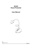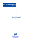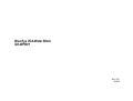
1
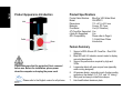
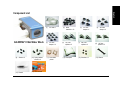
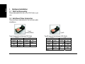
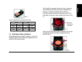
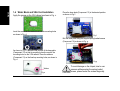
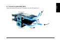
Blue Eye VGA Water Block
GH-WPBV1
Rev. 1001
060428
English
Table of Contents
Caution................................................................................................................................................3
Product Appearance Introduction........................................................................................................4
Product Specifications.........................................................................................................................4
Feature Summary ...............................................................................................................................4
Component List...................................................................................................................................5
I. Hardware Installation ....................................................................................................................6
1-1
1-2
1-3
1-4
VGA Fan Disassembly............................................................................................................ 6
Hold-Down Plates Introduction ............................................................................................... 6
Hold-Down Plates Installation................................................................................................. 7
Water Block and VGA Card Installation.................................................................................. 8
II. Water Tube Installation .................................................................................................................9
2-1
2-2
Water Tube Installation for Single VGA Card ......................................................................... 9
Water Tube Installation for Dual VGA Card .......................................................................... 10
III. Overview of Installed Water Block .............................................................................................. 11
2
English
Caution
1. Before refilling the tank with coolant for testing the Liquid cooling system, please make sure again that all water
tube joints are securely fitted and the clips are correctively positioned.
2. While removing water tubes for uninstallation, be sure to keep the device for removal of these tubes away from
any electronic part.
The following are not covered by the warranty:
1. Use the product incorrectly or in a manner other than the designed purpose.
2. Nonobservance of the proper operation provided. (e.g. over-clocking)
3. Malfunction due to interference from other devices.
4. Unapproved modification of the product.
5. Consequential damage to other objects due to the product’s fault.
6. Malfunction arising from casualties (earthquake, thunder, fire, and flood).
7. The product’s warranty label has been removed or damaged.
8. The devices inside, including power supply, hard disk, CD-ROM drive, motherboard, ventilator, etc, are not
detached from the casing prior to the transportation of the computer product, resulting in damage to the casing
or computer-related devices.
9. Any lose due caused by failure to follow the installation process contained in the user.
10. Any damage to the system arising from leakage of coolant due to improper installation is not covered by the
warranty.
11. Use only Gigabyte Liquid Coolant. Any damage arising from the use of liquids other than Gigabyte Liquid
Coolant is not covered by the warranty.
3
English
Product Appearance Introduction
Product Serial Number:
Model:
Dimensions:
Materials:
Flow Meter:
ATi CrossFire Supported:
nVidia SLi Supported:
GPU Compatibility:
Inlet
Outlet
Product Specifications
Base
Blue Eye VGA Water Block
GH-WPBV1
113 x 61.5 x 40.5 mm
Cooper, PC Cover
Yes (UV Reaction)
Yes
Yes
Please refer to Page 6;
1-2 Hold-Down Plates
Introduction
Feature Summary
1.
2.
3.
Please make sure that the protective film is removed
before use. Before the installation, please power
down the computer and unplug the power cord.
Please refer to the English version for all pictures.
4
4.
5.
6.
7.
Support nVIDIA Sli and ATi CrossFire – Dual VGA
Adaptors.
Blue LED with UV inductive current meter to display
current status directly.
Support the performance required by high-end
VGAs.
Large water block with pure cooper base (specially
water routing designed)
All-purpose design, supporting most of water-cooling
systems on the market. (1/4”, 3/8”, and 1/2” tubing)
Skid-proof and easy-to-install tube clamps
Hair-lined finished aluminum plate
English
Component List
(1) 1/4” tube x 1
GH-WPBV1 VGA Water Block
(9) Screws x 4
(10) Spring loaded
screws x 4
(15) Grease
(16) User manual
(2) RAM
heatsinks x 16
(3) 1/2” tube
clamps x 4
(4) 3/8” tube
clamps x 4
(5) 1/4” tube
clamps x 10
(6) 1/2” tube
splitters x 2
(7) 3/8” tube
splitters x 2
(8) 1/4” tube
splitters x 2
(11) Hold-down
plates
(12) Base plate
(13) Washers x 4
(14) Wrench
5
English
I. Hardware Installation
1-1 VGA Fan Disassembly
Please disassemble the fan on the VGA Card on your
own.
1-2 Hold-Down Plates Introduction
There are three combinations for the hold-down plate
installations.
Type A
(Factory Default)
Type A supports the following VGA Cards.
PCIE
nVIDIA
ATI
7900
X1900
7800
X1800
6800
6
AGP
nVIDIA
ATI
6800
Type B
Type B supports the following VGA Cards.
PCIE
nVIDIA
ATI
7300
X850
6200
X700
5750
X600
AGP
nVIDIA
ATI
1600
X800
X700
9800
9600
English
Type C
Take Type B for example. As shown in Fig. a, place the
disc hold-down plate with the engraved Gigabyte logo
facing up, so that the mounting holes on the disc
hold-down plate match with the mounting holes on the
base plate, and secure it with a fastener (as shown in Fig.
a).
Type C supports the following VGA Cards.
PCIE
nVIDIA
ATI
7600
1600
6600
1300
6200
AGP
nVIDIA
ATI
1300
1-3 Hold-Down Plates Installation
Please decide the type (Type A, Type B, or Type C) of
hold-down plate for your VGA Card, depending on the
position of the mounting holes.
Mounting
holes on the
base plate
Fig. a
Secure the disc hold-down plate by tightening the screws
(Component 9) with the wrench (Component 14) as
shown in Fig. b.
Fig. b
7
English
1-4 Water Block and VGA Card Installation
Apply the grease on the VGA chipset as shown in Fig. c.
Insert the screws on the water block into the mounting holes
as shown in Fig. d.
Place the base plate (Component 12) in the desired position
as shown in Fig. f.
Fig. f
Bolt the base plate using the supplied spring loaded screws
(Component 10) as shown in Fig. g.
As shown in Fig. e, determine the position of the base plate
(Component 12) so that its mounting holes line up with the
mounting holes on the VGA radiator. Place the washers
(Component 13) on the lined up mounting holes, as shown in
Fig. e.
Fig. g
Washer
Fig. e
8
To avoid damage on the chipset, due to over
pressure while securing the spring loaded
screws, please fasten the screws diagonally.
2-1 Water Tube Installation for Single VGA
Card
Please follow the procedures shown on the diagram on the
left to proceed with the installation for single VGA card. The
water-cooling system used in the example is Gigabyte 3D
Galaxy.
Procedure 1:
Cut the supplied water tube connected to the radiator and
CPU water block and the supplied water tube connected to
the CPU water block and pump.
Procedure 2:
Connect cut ends with the supplied 1/2” splitters (Component 8) and
secure firmly with the supplied 1/2” tube clamps (Component 5).
Procedure 3:
Connect the supplied 1/4” water tubes (Component 1) to the
supplied 1/2” splitters (Component 8) and the other ends to
the VGA water block inlet and outlet. Make sure all the tube
clamps are secured firmly.
Procedure 4:
To connect the 4-pin
connector of the LED
power line to the power
line of the power supply.
Procedure 5: Installation completed.
If the CPU water-cooling systems from other
brands are used, please follow the size regulation
for the water tubes for installation.
Procedure 1: Cut the
tube here.
CPU Water
Block
Procedure 1: Cut the
tube here.
English
II. Water Tube Installation
Procedure 2:
Connect with
the 1/2” tube
splitter.
Procedure 2:
Connect with the 1/2”
tube splitter.
Radiator
Water Pump
Tube
Procedure 3: Connect the tubes
to the water block outlet.
Tube
Procedure 3: Connect the tubes
to the water block inlet.
VGA Water
Block
1/2” tube
1/4” tube
Before filling the coolant, please make sure that
all the tube clamps are secured firmly.
9
English
2-2 Water Tube Installation for Dual VGA Card
Procedure 1 and 2:
Same as in the water tube installation for single VGA
card.
Procedure 3:
Connect one end of the supplied 1/4” water tube
(Component 1) to the supplied 1/2” splitter (Component 8)
and the other end to the VGA water block 1 inlet. Connect
the VGA water block 1 outlet and the VGA water block 2
inlet with another supplied 1/4” water tube (Component 1).
Finally connect one end of the other supplied 1/4” water
tube (Component 1) to the VGA water block 2 outlet and
the other end to the supplied 1/2” splitter (Component 8).
Make sure all the tube clamps are secured firmly.
Tube
Tube
Procedure 3: Water
Block Outlet
Procedure 3: Water
Block Outlet
Procedure
3: Water
Procedure 3:
Water Block Inlet
Block Inlet
Procedure 4: Installation of single graphic card
Procedure 5: Installation Completed
VGA Water
Block 1
VGA Water
Block 2
1/2” tube
If the CPU water-cooling systems from other
brands are used, please follow the size regulation
for the water tubes for installation.
10
1/4” tube
Before filling the coolant, please make sure that
all the tube clamps are secured firmly.
English
III. Overview of Installed Water Block
Please make sure the VGA water block 1 is installed on top of the VGA water block 2.
VGA water block 1
out
in
VGA water block 2
11
12
English