1
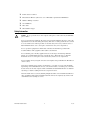
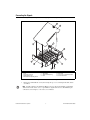
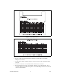
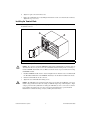
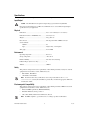
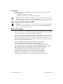
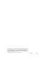
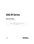
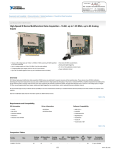
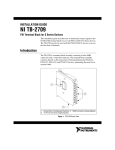
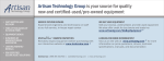
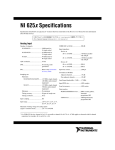
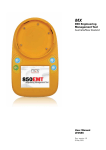
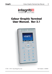
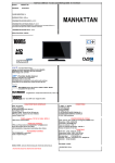
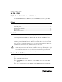
INSTALLATION GUIDE
NI TB-2706
PXI/PXIe Terminal Block for M Series and NI 6143 Devices
This installation guide describes how to install and connect signals to the NI TB-2706 terminal block
for use with PXI/PXIe M Series, NI PXI-6143, and other PXI/PXIe devices with a 68-pin VHDCI
connector.
Contents
Introduction.......................................................................................................................................... 1
What You Need to Get Started ............................................................................................................ 1
Safety Information ............................................................................................................................... 2
Connecting the Signals ........................................................................................................................ 3
Installing the Terminal Block .............................................................................................................. 5
Specifications....................................................................................................................................... 6
Where to Go for Support ..................................................................................................................... 7
Introduction
The TB-2706 is a terminal block assembly consisting of a printed circuit board, 70 screw terminals, and
a metal enclosure with strain relief hardware. The terminal block assembly connects directly to the front
panel of National Instruments PXI-622x, PXI-625x, PXIe-625x, PXI-628x, and PXI-6143 devices,
eliminating the need for an external cable.
The TB-2706 allows you to easily connect analog input, analog output, counter/timer, and digital I/O
signals to your National Instruments device. The 70 screw terminals allow access to every pin on the
connector, plus two shield screw terminals for use with a shielded cable. For M Series devices with
two connectors, this terminal block allows access to every pin on Connector 0, plus two shield screw
terminals for use with a shielded cable, but makes Connector 1 inaccessible.
Caution The TB-2706 is not designed for input voltages greater than 42 Vpk/60 VDC, even if you
install a voltage divider that reduces the voltage to within the input range of the DAQ device. Input
voltages greater than 42 Vpk/60 VDC can damage the TB-2706, any device connected to it, and the
host computer. Overvoltage also can cause an electric shock hazard for the operator. National
Instruments is not liable for damage or injury resulting from such misuse.
What You Need to Get Started
You need the following to set up and use your terminal block:
❑ NI TB-2706 Terminal Block Assembly
❑ NI TB-2706 Installation Guide
❑ NI PXI/PXIe M Series device, NI PXI-6143, or other PXI/PXIe device with a 68-pin VHDCI
connector
❑ M Series User Manual, S Series User Manual, or other PXI/PXIe DAQ device documentation
❑ 0.10 in. slotted screwdriver
❑ Pinout label for M Series (adhered to cover of TB-2706) or pinout list for NI PXI-6143
❑ Number 1 Phillips screwdriver
❑ 26–16 AWG wire
❑ Wire cutters
❑ Wire insulation stripper
Safety Information
Cautions Do not operate the device in an explosive atmosphere or where there may be flammable
gases or fumes.
Do not operate damaged equipment. The safety protection features built into this device can become
impaired if the device becomes damaged in any way. If the device is damaged, turn the device off and
do not use it until service-trained personnel can check its safety. If necessary, return the device to
National Instruments for service and repair to ensure that its safety is not compromised.
Do not operate this equipment in a manner that contradicts the information specified in this
document. Misuse of this equipment could result in a shock hazard.
Do not substitute parts or modify equipment. Because of the danger of introducing additional
hazards, do not install unauthorized parts or modify the device. Return the device to National
Instruments for service and repair to ensure that its safety features are not compromised.
You must insulate all of your signal connections to the highest voltage with which the TB-2706 can
come in contact.
Connections, including power signals to ground and vice versa, that exceed any of the maximum
signal ratings on the terminal block can create a shock or fire hazard, or can damage any or all of the
boards connected to the host computer, and the terminal block. National Instruments is not liable for
any damages or injuries resulting from incorrect signal connections.
Clean the module and accessories by brushing off light dust with a soft non-metallic brush. Remove
other contaminants with a stiff non-metallic brush. The unit must be completely dry and free from
contaminants before returning it to service.
NI TB-2706 Installation Guide
2
ni.com
Connecting the Signals
Refer to Figure 1 as you complete the following steps to connect signals to your terminal block.
1
2
3
13
4
12
5
11
6
10
9
8
1
2
3
4
5
Top Cover Screw
Cover
Chassis Ground Lug
Strain-Relief Screw
Terminal Block Mounting Screw
6
7
8
9
Strain-Relief Bar
Signal Wire
Strain-Relief Opening
Base
7
10
11
12
13
Screw Terminals
Base Tab
Connection to PXI/PXIe Module
Cover Indentation
Figure 1. TB-2706 Parts Locator Diagram
1.
Remove the terminal block cover by unscrewing the top cover screw using the 0.10 in. slotted
screwdriver.
Note Your kit contains a pinout label for M Series devices only, shown in Figure 2. This label,
adhered to the inside of the cover, is a pin number-to-signal name reference. For PXI-6143 pin
connections, refer to Figure 3 or the S Series User Manual.
© National Instruments Corporation
3
NI TB-2706 Installation Guide
Figure 2. Pinout Label for M Series
Figure 3. Pinout for PXI-6143
2.
Loosen or remove the strain-relief bar by loosening the two strain-relief screws with the
Phillips-head screwdriver.
3.
Use wire cutters and wire insulation strippers to strip no more than 7 mm of insulation from the
wire ends.
4.
Loosen the screws in the screw terminals with the 0.10 in. slotted screwdriver.
5.
Insert the stripped wires into the screw terminals. Tighten the screws with the 0.10 in. slotted
screwdriver. No bare wire should extend past the screw terminal. Exposed wire increases the risk
of short circuits and failures.
NI TB-2706 Installation Guide
4
ni.com
6.
Tighten or replace the strain-relief screws.
7.
Replace the terminal block cover by sliding the indentations on the cover under the tabs on the base.
Tighten the top cover screw.
Installing the Terminal Block
Refer to Figure 4 as you complete the following steps to connect the terminal block to the PXI/PXIe
module I/O connector.
2
3
2
3
4
1
5
6
7
8
1
Terminal Block Mounting Screws
2
PXI/PXIe Chassis
3
PXI/PXIe Module Connector
Figure 4. Connecting the TB-2706 to an M Series or PXI-6143 Device
Caution The connectors of both the PXI/PXIe module and the terminal block are polarized. You can
attach them in only one way. Do not force the terminal block when inserting it into or removing it
from the PXI/PXIe module I/O connector. Make sure that the chassis is powered off before inserting
the PXI/PXIe module.
1.
Install the PXI/PXIe module into the chassis and tighten the two module screws. You must install
the TB-2706 terminal block on the PXI/PXIe module after the module is installed in the chassis.
2.
Guide the terminal block onto the connector.
3.
Tighten the two terminal block mounting screws.
Caution The TB-2706 is not designed for input voltages greater than 42 Vpk/60 VDC, even if you
install a voltage divider that reduces the voltage to within the input range of the DAQ device. Input
voltages greater than 42 Vpk/60 VDC can damage the TB-2706, any device connected to it, and the
host computer. Overvoltage also can cause an electric shock hazard for the operator. National
Instruments is not liable for damage or injury resulting from such misuse.
© National Instruments Corporation
5
NI TB-2706 Installation Guide
Specifications
These specifications are typical at 25 °C unless otherwise specified.
Input/Output
Caution
The TB-2706 is not designed for input voltages greater than 42 Vpk/60 VDC.
Refer to the documentation for your M Series or PXI-6143 device to determine the input/output
specifications for your application.
Physical
Dimensions ............................................................10.7 × 8.6 × 2.0 cm (4.2 × 3.4 × 0.8 in.)
Dimension from face of PXI/PXIe card.................8.6 cm (3.4 in.)
Weight ....................................................................289 g (10.2 oz)
I/O connector .........................................................One 68-position male VHDCI connector
Screw terminals
Number ..........................................................70
Type................................................................Angled entry, 3.81 mm pitch
Wire gauge .............................................................26–16 AWG
Environment
Operating temperature ...........................................0 to 55 °C
Storage temperature ...............................................–20 to 70 °C
Relative humidity...................................................10 to 90% noncondensing
Pollution Degree (indoor use only)........................2
Altitude ..................................................................2,000 m
Safety
This product is designed to meet the requirements of the following standards of safety for electrical
equipment for measurement, control, and laboratory use:
•
IEC 61010-1, EN 61010-1
•
UL 61010-1, CSA 61010-1
Note For UL and other safety certifications, refer to the product label or visit ni.com/
certification, search by model number or product line, and click the appropriate link in the
Certification column.
Electromagnetic Compatibility
This product is designed to meet the requirements of the following standards of EMC for electrical
equipment for measurement, control, and laboratory use:
•
EN 61326 EMC requirements; Minimum Immunity
•
EN 55011 Emissions; Group 1, Class A
•
CE, C-Tick, ICES, and FCC Part 15 Emissions; Class A
Note
For EMC compliance, operate this device according to product documentation.
NI TB-2706 Installation Guide
6
ni.com
CE Compliance
This product meets the essential requirements of applicable European Directives, as amended for
CE marking, as follows:
•
73/23/EEC; Low-Voltage Directive (safety)
•
89/336/EEC; Electromagnetic Compatibility Directive (EMC)
Note
Refer to the Declaration of Conformity (DoC) for this product for any additional regulatory
compliance information. To obtain the DoC for this product, visit ni.com/certification,
search by model number or product line, and click the appropriate link in the Certification column.
Waste Electrical and Electronic Equipment (WEEE)
EU Customers At the end of their life cycle, all products must be sent to a WEEE recycling center.
For more information about WEEE recycling centers and National Instruments WEEE initiatives,
visit ni.com/environment/weee.htm.
Where to Go for Support
The National Instruments Web site is your complete resource for technical support. At ni.com/
support you have access to everything from troubleshooting and application development self-help
resources to email and phone assistance from NI Application Engineers.
National Instruments corporate headquarters is located at 11500 North Mopac Expressway, Austin,
Texas, 78759-3504. National Instruments also has offices located around the world to help address your
support needs. For telephone support in the United States, create your service request at ni.com/
support and follow the calling instructions or dial 512 795 8248. For telephone support outside the
United States, contact your local branch office:
Australia 1800 300 800, Austria 43 662 457990-0, Belgium 32 (0) 2 757 0020,
Brazil 55 11 3262 3599, Canada 800 433 3488, China 86 21 5050 9800,
Czech Republic 420 224 235 774, Denmark 45 45 76 26 00, Finland 385 (0) 9 725 72511,
France 33 (0) 1 48 14 24 24, Germany 49 89 7413130, India 91 80 41190000, Israel 972 3 6393737,
Italy 39 02 413091, Japan 81 3 5472 2970, Korea 82 02 3451 3400, Lebanon 961 (0) 1 33 28 28,
Malaysia 1800 887710, Mexico 01 800 010 0793, Netherlands 31 (0) 348 433 466,
New Zealand 0800 553 322, Norway 47 (0) 66 90 76 60, Poland 48 22 3390150,
Portugal 351 210 311 210, Russia 7 495 783 6851, Singapore 1800 226 5886,
Slovenia 386 3 425 42 00, South Africa 27 0 11 805 8197, Spain 34 91 640 0085,
Sweden 46 (0) 8 587 895 00, Switzerland 41 56 2005151, Taiwan 886 02 2377 2222,
Thailand 662 278 6777, Turkey 90 212 279 3031, United Kingdom 44 (0) 1635 523545
© National Instruments Corporation
7
NI TB-2706 Installation Guide
National Instruments, NI, ni.com, and LabVIEW are trademarks of National Instruments Corporation.
Refer to the Terms of Use section on ni.com/legal for more information about National
Instruments trademarks. Other product and company names mentioned herein are trademarks or trade
names of their respective companies. For patents covering National Instruments products, refer to the
appropriate location: Help»Patents in your software, the patents.txt file on your CD, or
ni.com/patents.
© 2005–2007 National Instruments Corporation. All rights reserved.
371459B-01
Apr07