1
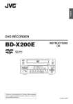
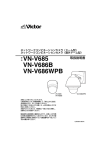
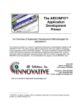
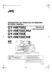
FIXED IP DOME CAMERA (Vandal Resistant)
FIXED MEGAPIXEL IP DOME CAMERA (Vandal Resistant)
VN-V225VPU
VN-X235VPU
READ ME FIRST
Cable Connection
Processes after connection
For safety reasons, turn on the power only after all the connections are completed.
When power is supplied to the camera, the [STATUS] indicator lights up. The indicator lights up in orange during
startup and turns green when startup is complete.
Fill up the piping hole and mounting hole with sealant and insert the silica gel.
Thank you for purchasing this JVC product.
Before operating this unit, please read the instructions carefully to ensure the best possible performance.
䡵 This manual contains the basic instructions for using this unit.
Please refer to [INSTRUCTIONS (Setting)] (pdf) and [INSTRUCTIONS (Installation)] (pdf) in the CD-ROM
supplied with this product for description on the detailed usage of this unit.
For the latest information, please refer to the AREADMEB file in the CD-ROM supplied with this product.
● The supplied CD-ROM includes [INSTRUCTIONS (Setting)] (pdf), [INSTRUCTIONS (Installation)]
(pdf), [API Guide] (pdf), [VSIP Guide] (pdf) and [Search tool], [White Spot Correction Tool].
Alarm cable to use (Recommended shield cable)
● Length of 50 m or shorter
● UL1007, UL1015 or equivalent products
● AWG#22 to AWG#18 or equivalent products
T To use the PoE power supply, connect to a PoE-compatible device and supply the power from the
LAN cable.
Note:
● When using a heater unit (sold separately: KA-ZH215U), PoE power supply does not work
for the heater unit (KA-ZH215U). Be sure to use an AC 24 V power supply.
● JVC holds the copyright to this manual. Any part or all of this manual may not be reproduced without prior consent
from the company.
● Windows is a registered trademark of Microsoft Corporation in the U.S.
● Product names of other companies described in this manual are trademarks or registered trademarks of the
respective companies. Symbols such as 姠, 姞 and 姝 are omitted in this manual.
● Design, specifications and other contents described in this manual are subject to change for improvements without
prior notice.
● Connecting to HUB
● Connecting to a computer
䡵 The latest version
1
7 Hold and press the focus adjust gear between your fingers in the
Space for inserting
the silica gel
8
4 Connect the power cable
Note:
● The power supply cable includes cable of the same color as the alarm cable. Check properly before
connecting.
● Make sure that power is supplied using only one of the above methods at any one time. Connecting
simultaneously using the power cable and to PoE via a LAN cable may cause the camera to break
down or malfunction.
● By default the IP addresses of all the cameras are set to 192.168.0.2. If the power of multiple
cameras within the same LAN environment are turned on at the same time, the IP addresses of the
cameras overlap, thus preventing proper access. As such, make sure to turn on the power of the
cameras one by one and set the IP addresses such that there is no overlapping.
Installation
Mounting the Camera
Setting Up the Camera
● The camera enters the focus adjust mode and the [STATUS] indicator blinks in green
and orange alternately.
● The image is sharpened with the opening of the lens iris.
● The center of the image is enlarged. (VN-X235VPU only)
● After adjusting the focus, press the [RESET] button for more than 2 seconds but less
than 5 seconds to release the focus adjust mode.
B Shoot the subject
● Return the catch to A in the diagram, and then rotate the knob to adjust the focus to the
optimum position.
D Rotate the focus adjust gear knob about one base pitch in the direction of the arrow
in the diagram.
● This is to correct the focus shift when mounting the dome cover.
E Hold the dome cover over the lens and check the focus
: Use a straight cable
: Use a cross cable
Power can be supplied to this unit either by connecting to an AC 24 V power supply or using
PoE. (To use PoE A [3 Connect the LAN cable])
Please visit V.NETWORKS web site to check the latest firmware at
http://www.jvc-victor.co.jp/english/products-e.html
(The latest firmware can be found on V.NETWORKS B download page)
right to adjust the focus.
C Fine adjust the focus
2
LAN cable to use
● STP (Recommended shield cable)
● Length of 100 m or shorter
● Category 5 and above
B Loosen the fastening screw of the focus adjustment ring, move it to the left and
A Press the [RESET] button for more than 2 seconds but less than 5 seconds.
Note:
● Please make sure that rain does not seep into this unit when mounting on rainy days.
● Be sure to use the silica gel (provided). Failure to do so may fog up the camera lens and dome cover.
● If field angle is not adjusted immediately after mounting the camera, insert the silica gel (provided) after
adjustment. The silica gel (provided) will lose its effectiveness if it is exposed to the air for a long time.
3 Connect the LAN cable
● The gear is disengaged.
Note:
● If the gear is moved outwards from B, the shaft of the gear may shift. For details on how
to return the gear to the original position, refer to ( A [INSTRUCTIONS (Installation)]) in
the supplied CD-ROM.
6 Fine adjust the focus
2 Insert the silica gel (provided)
2 Connect to audio cable (Recommended shield cable)
䡵 How to read this READ ME FIRST
1 Use sealant (GE silicon) to fill up the mounting holes (x2) to which
Note:
● Make sure the holes are completely sealed up. Water or moisture may seep in and fog up the
lens and dome cover.
Connect the alarm cable to an external device, such as a sensor or buzzer.
VN-X235VPU is a high definition surveillance camera that uses high resolution CCD sensors with 4 times
the pixel count of VN-V225VPU.
A Lift the focus adjust gear knob, and place the catch into B in the diagram
the piping hole and screws are mounted
1 Connect the alarm cable
LST0849-001B
5 Roughly adjust the focus
direction of the arrows in the diagram, and tighten the fastening
screw of the focus adjustment ring
Set the [MONITOR OUT] selector switch to AOFFB, then press the
[RESET] button shortly (less than 2 seconds)
● The camera restarts, and the focus assist mode is released.
Sealant
(GE silicon)
Knob Catch B
T This illustration is for the
purpose of explanation, and
does not represent the
actual camera.
A
Zoom adjustment ring
Focus adjustment ring
5
Silica gel (Provided)
Lug plate
䡵 Type of cable
Type
1 Remove the dome cover with the wrench provided (Screws x3)
2 Grab the inner dome and remove it from the catches (x3)
Color
Black
(shielded cable)
Alarm cable
Inner dome
Audio cable
Wrench (provided)
Dome
cover
Fall
prevention
wire
(not
removable)
Catches
(x3)
Power cable
Signal Name
Red
Alarm input 1
Brown
Alarm input 2
Adjusting Images
Orange
Alarm output 1
When the camera is mounted, adjust the image settings while looking at the actual image.
Before touching the body of the camera, make sure to touch the metal surface of the [MONITOR] terminal to
discharge the static electricity from your body. The static electricity may cause the camera to malfunction.
Yellow
Alarm output 2
Black
GND
Brown
(shielded cable)
White
MIKE IN
Yellow
GND
Black
(shielded cable)
White
LINE OUT
Yellow
GND
Red (unshielded cable)
Camera
AC 24 V Power Supply
Conductor diameter (mm)
R1.0 and above
R1.6 and above
R2.0 and above
Maximum connection distance (m)
130
340
540
Maximum connection distance (m) with
Heater (KA-ZH215U)
40
120
180
A Unscrew the mounting screw for the fall prevention wire beneath the camera and mount
the fall prevention wire.
B Mount the fall prevention wire to a strong location.
3
2,6
[STATUS] indicator
[RESET] button
1
Test monitor
75 K
terminated
1 Mount the inner dome to the catches (x3)
Rotation: ±175 ⬚
Tilt: ±70 ⬚
Shooting direction
mark
Pan center mark
Rotation center
mark
2 Mount the dome cover
A Remove and clean any dust or dirt on the dome cover.
B Align the base with the position alignment marks (x3) on the dome cover and mount
the dome cover.
C Tighten and secure the dome cover fastening screws (x3).
Position alignment mark (x3)
Catches
(x3)
Memo:
● When mounting the heater unit (sold
separately: KA-ZH215U), please refer to
the KA-ZH215U [INSTRUCTIONS].
2
1,2,4
6 mm and below
Mounting the Dome Cover
Rotation control (x4)
Fall prevention wire (not provided)
2 mm
Pan: ±175 ⬚
[MONITOR OUT] selector switch
[MONITOR] terminal
Space for heater
R30 mm (1-1/8 inch)
8 mm
One base pitch
3 Adjust the shooting direction of the camera
5 Wind the waterproof tape
Pull out the cables from the ceiling and the cables from the camera towards the lens as shown, face
the (D) mark in the shooting direction, then mount the camera to the ceiling. To mount on a wall,
mount the camera such that the (D) mark is facing upwards.
T Screws for mounting the camera are not provided. Use the appropriate type of screws according
to the material of the location for mounting.
䡵 Fall prevention wire
Base
Shooting
direction mark
● The camera reboots. (approximately 1 minute)
● During the restart, the [STATUS] indicator lights up in orange.
● Set to ANB when connecting to a NTSC monitor or set to APB when connecting to a PAL monitor.
Note:
● For cables that are not used, be sure to wrap the ends individually with insulating tape.
3 Mount the camera to the ceiling
1
power or press and hold the [RESET] button for less than 2 seconds
The rated power of this product is AC 24 V, 50 Hz/60 Hz. Make sure to use it with the correct
voltage.
Be sure to use an AC 24 V supply that is insulated from the primary power source.
Supplying a power beyond the rated value may result in failures, smoke or fire. If the camera
breaks down, turn off the power and contact our service center immediately.
When a power beyond the rated value is supplied, the internal components may be
damaged even if no abnormality is found on the appearance and operation of the camera.
Please send to your nearest JVC dealer immediately for servicing (charged separately).
T Fall prevention wire is not provided. Prepare a wire with due consideration of the length, strength,
pull factor and material (insulative).
7
Adjust the camera for pan, tilt and rotation, and face the camera towards the subject.
Caution
1 Use the provided template to make a R30 mm (1-1/8 inch) hole in the ceiling.
2 Mount the fall prevention wire that connects the camera to the ceiling.
3
10BASE-T/100BASE-TX(PoE)
terminal
R12 mm and below
Solder welding
or crimping
Wind the
insulation tape
R4.1_6.5 mm
3
R4 mm screw ×2 (not provided)
Note:
● To mount the camera using electrical box or piping, please refer to (A [INSTRUCTIONS
(Installation)]) in the bundled CD-ROM.
5
Wind the
waterproof
tape
Tilt fastening screw
Memo:
● Rotate both pan and rotation ±175⬚ from the positions aligned with the camera’s shooting
direction mark, pan center mark and rotation center mark. Be sure to hold the rotation control
and adjust the rotation without holding the lens section.
● After adjusting the field angle, tighten and secure the tilt fastening screw so that the field angle
will not be misaligned.
Note:
● Moving the camera when it has exceeded the adjustment range may cause its performance to
deteriorate.
● As the tilt and rotation range of this unit is wide, part of this unit may be reflected in the shooting
screen depending on the field angle and direction.
● Do not hold the lens section when adjusting the camera direction. The lens section may be
damaged if you apply force to it.
4 Adjust the image size
Loosen the fastening screw of the zoom adjustment ring, move the ring to the left and right to
adjust the image size. After adjusting, fasten the screw with pressing it slightly toward the lens
direction (toward the shooting direction).
LAN cable
B Catch A
2 Set the [MONITOR OUT] selector switch to ANB or APB, turn on the
䡵 Power cable Connection distance when using 2-core VVF cable (Reference values)
Mount the camera to the ceiling or wall.
To mount on a wall, perform the same procedures below but replace the word “ceiling” with “wall”.
Knob
6
1 Connect the [MONITOR] terminal to the test monitor
Black (unshielded cable)
Mounting the Camera
Focus adjust gear
Base
B
C
Inner dome
Dome
cover
Wrench (provided)
Note:
● Check that the silica gel (Provided) has been inserted before mounting the dome cover.
● Ensure that the dome cover is secured. Insecure mounting may increase humidity, fog up the
camera or the cover may drop.
● When the cover is removed again after mounting the dome cover, check the field angle and readjust the focus and field angle if necessary.
● Make sure that the fall prevention wire of the dome cover is not caught between the dome cover
and the base. Otherwise, the anti-dust and waterproof function may not work properly.
LAN cable stopper (x2)
K
Continued
3
Setting
K
If the active script of the Internet Explorer is disabled, follow the steps below to enable it
IP Address Settings
● Select [Trusted sites] under [Tool]-[Internet Options]-[Security]. Upon doing so, the [Sites...] button
directly below becomes active. Click this button, deselect the check in the displayed window, and add the
following web site to the zone.
http://192.168.0.2 (When the camera is in its default settings)
This section is a description based on Windows XP.
● Next, select [Trusted sites] under [Tool]-[Internet Options]-[Security], and press the [Custom Level]
button. Select [Enable] under [Scripting]-[Active script] of the [Security Settings] window that is opened.
Setting Using Internet Explorer
A
B
Configure the picture quality setting, alarm setting and other settings using the Internet Explorer.
T For details, please refer to [INSTRUCTIONS (Setting)] (pdf) in the supplied CD-ROM.
IP address setting procedure
C
Follow the procedure below to configure the IP address of the camera.
Step1 IP address setting at the computer
Select [Enable]
Memo:
● After the [Security Settings] screen appears, press the [Yes] button to proceed.
Set the IP address of the computer that is used for configuring the camera settings.
K
3
Step2 Internet Explorer settings
Built-in Viewer and the operator password entry screen appear
A Enter the Operator Password. (default password is AjvcB)
B Click [OK].
Configure the Internet Explorer settings in order to establish connection between the computer and the camera.
K
Operating the Built-in Viewer
With the built-in viewer, you can monitor JPEG and MPEG4 images and audio.
And on VN-X235VPU, you can perform PTZ operation and configure PTZ related settings.
T For details, please refer to [INSTRUCTIONS (Setting)] (pdf) in the supplied CD-ROM.
K
Step3 Connecting the camera to the computer
Connect the computer to the camera.
4 If ActiveX controls and plug-ins of the Internet Explorer is disabled, follow the steps
below to enable it
K
Step4 IP address setting for the camera
Set the [IP Setting] item on the [Basic Settings1] screen to ADHCP DisableB or ADHCP EnableB.
Step1 IP address setting at the computer
Operating Environment
● Click [Trusted sites] under [Tool]-[Internet Options]-[Security]. Select the [Custom Level] button to open
the [Security Settings] window. Set all items under [ActiveX controls and plug-ins] in the opened window
to [Enable]. Enable also [Allow Script-initiated window without size or position constraints] under
[Miscellaneous].
Recommended Computer Specifications
OS
Camera at factory default is set to ADHCP DisableB (DHCP client function is Off), it will activate under the
following IP address after startup. Set the computer to an IP address that enables communication with the
following. (For example, set the IP address to 192.168.0.100 and subnet mask to 255.255.255.0.)
IP address
: 192.168.0.2
Subnet mask
: 255.255.255.0
Default gateway : None
CPU
A
䡵 IP address setting at the computer
B
Set the computer to an IP address that enables communication with the camera.
1
Memory capacity
Free hard disk space
Display and video card
Web browser
Click [Start]
● Select in the sequence of [Control Panel]-[Network Connection]-[Local Area].
Windows Vista:
● Select in the sequence of [Settings]-[Control Panel]-[Network and Sharing Center]-[Manage
network connections].
Step4 IP address setting for the camera
1
LAN Environment
Click [Details] of the Built-in Viewer
2
The computer on which Internet Explorer is launched automatically selects the
connected network
● Right-click and select [Properties].
● Check to ensure that the [Client for Microsoft Networks] and [Internet Protocol(TCP/IP)] check boxes are
selected.
Windows Vista:
● Check to ensure that the [Microsoft Network Client] and [Internet Protocol Version 4(TCP/IPv4)]
check boxes are selected.
3
Select [Internet Protocol(TCP/IP)] and click [Properties]
Windows Vista:
4
● Select [Internet Protocol Version 4(TCP/IPv4)] and click [Properties]
: Windows XP (Professional or Home Edition) (SP2)
Windows Vista Business (SP1)
: Pentium4 1.5 GHz or higher (VN-V225VPU)
Pentium4 2 GHz or higher (VN-X235VPU)
: 1 GB and above
: 512 MB or more
: 1024⳯768 pixels or higher (VN-V225VPU),
1600⳯1200 pixels or higher (VN-X235VPU)
True Color (24 bit or 32 bit) VRAM 8 MB or more (256 MB and above
recommended)
: Internet Explorer
XP
: Version 6.0
Vista : Version 7.0
Click
5 Disable pop-up block
Connection of the camera cannot be established when pop-up block in the Internet Explorer is set to
AEnableB. Follow the steps below to set the pop-up block to ADisableB.
● 10BASE-T/100BASE-TX network interconnected using devices such as an IEEE802.3-compliant
switching hub.
● IEEE802.3af-compliant switching hub when PoE is used
● IGMPv2-compliant network when multicast is in use.
Memo:
● To use MPEG4 images on the built-in viewer, install the open source codec “ffdshow”. You can download
“ffdshow” from the Internet. JVC is not responsible for any damages resulting from your use of open
source software.
● Selecting [Tool]-[Pop-up Blocker]-[Turn Off Pop-up Blocker] permits all sites.
● To allow only specific sites such as this unit, select [Tool]-[Pop-up Blocker]-[Turn Off Pop-up Blocker],
followed by selecting [Tool]-[Pop-up Blocker]-[Pop-up Blocker Settings], which becomes active to open
the [Pop-up Blocker Settings] window.
In the opened window, add the address of the camera as a permitted web site address.
Specifications
6 When plug-in tools such as the Yahoo or Google toolbar are included in the Internet
Explorer, disable the pop-up block function of these plug-in tools as well
Set the IP address
Supply voltage
A Select [Use the following IP address].
B Specify the [IP address]. (For example, use 192.168.0.100 when the camera is in its default
settings.)
Memo:
● Make sure that you take note of the original IP address before altering.
● Ensure that a duplicate IP address is not specified within the same network environment.
Step3 Connecting the camera to the computer
1
2
Launch the Internet Explorer
A Enter the IP address of the camera. (http://192.168.0.2, for example)
B Click [Go].
A
C Set [Subnet mask] to a value that is appropriate for the setting operation. Consult the network
䡵When selecting ADHCP DisableB:
Select ADHCP DisableB from [IP Setting] item of the camera, and specify a value in the [IP address],
[Subnet Mask] and [Default Gateway] fields.
B
administrator if you have any queries. (Use 255.255.255.0 when the camera is in its default
settings.)
The [Basic Settings1] screen appears
A Specify the [IP Setting].
䡵When selecting ADHCP EnableB:
The default setting is ADHCP DisableB (DHCP client function is off).
To assign an IP address from the DHCP server, connect the camera to a LAN where the DHCP server
exists.
For details on the IP address assigned to the camera, consult your network administrator.
B Specify the [Time Zone].
D When a [Default gateway] is present, make use of the corresponding IP address (e.g., 192.168.0.254).
E Click [OK].
A
C Click [OK].
: AC 24 V 50 Hz/60 Hz or PoE (DC -48 V)
AC 24 V 50 Hz/60 Hz (when KA-ZH215U is in use)
Current consumption
: AC 24 V 0.35 A, PoE 7.0 W
AC 24 V 1.0 A (when KA-ZH215U is in use)
Mass
: Approx 1.3 kg (2.87 Ibs)
Ambient temperature
: -10 I to 50 I (operation)
0 I to 40 I (recommended)
When KA-ZH215U is in use : -30 I to 50 I (operation)
-20 I to 40 I (recommended)
Ambient humidity
: 35 % RH to 90 % RH (without condensation)
䡵 Accessories
●
●
●
●
●
●
●
●
SAFETY PRECAUTIONS
Read Me First
CD-ROM
Warranty Card (For USA)
Service Information Card (For USA)
Template
Wrench
Silica gel
䡵 Dimension [Unit: mm (inch)]
B
C
Step2 Internet Explorer settings
1
2
Launch the Internet Explorer on the computer
If proxy settings are enabled in the Internet Explorer, follow the steps below to disable
the proxy of the Internet Explorer
● Select in the order of [Tool]-[Internet Options]-[Connections]-[LAN Setting], followed by deselecting the check for
[Use a proxy server for your LAN] under [Proxy Server] of the [Local Area Network (LAN) Settings] window.
䡵 If the IP address is unknown
IP address settings cannot be changed by accessing via a computer when the IP address of the camera is
unknown.
You can use the following method to identify the IP address.
● Search using the ASearch toolB inside the ATOOL_EB folder of the supplied CD-ROM.
T For details on ASearch toolB, please refer to the AREADMEB file in the CD-ROM supplied with this
product.
2
Enter the user name and password (login as administrator)
A Enter the user name. This is set to AadminB by default.
B Enter the password. This is set to AjvcB by default.
C Click [OK].
B
[Basic Settings1] screen
9
(3/8)
Note:
● Set the DHCP server such that the same IP address is always assigned to the MAC address of the
camera by the DHCP server. Connection may fail if the above setting is not performed.
3
A confirmation screen appears
G3/4-14 UNC screw
for piping (bottom)
125(4-7/8)
Click [OK] on the [Local Area Connection Properties] screen
0
16
.7 )
53 -1/8
SR (2
5
G3/4-14 UNC screw
for piping (side)
4
1/
(6
42(1-5/8)
E
121(4-3/4)
113(4-1/2)
A
5(1/4)
Memo:
● If the proxy server settings for access to the Internet via the Internet Explorer is enabled, you may not be
able to specify the IP address directly. In this case, change the proxy settings of the Internet Explorer.
● To open the [Basic Settings1] page without going through the built-in viewer, enter the URL of the [Basic
Settings1] page in the address field of the Internet Explorer.
● VN-V225VPU:
http://192.168.0.2/cgi-in/v225display.cgi?v225basicmenu1.html
● VN-X235VPU:
http://192.168.0.2/cgi-in/x235display.cgi?x235basicmenu1.html
● After the [Security Settings] screen appears, press the [OK] button to proceed.
C
D
160(6-1/4)
● Click [OK].
● The camera restarts using the new IP address. It takes about one minute for the camera to restart.
Memo:
● Access from this computer may fail when the IP address of the camera is changed. To enable access to
this unit from the same computer, alter the IP address of the computer accordingly.
T Specifications and appearance of this unit are subject to change for further improvements without prior
notice.
When the display or configuration of the opened screen appears strange, check the computer
settings using the following procedures.
Deselect the check
A
B
C
D
Click [Start]-[Control Panel]-[Display] and open the [Display Properties] window
Click the [Settings] tab in the [Display Properties] window, followed by the [Advanced] button
Check that [DPI setting] in the [General] tab has become [Normal size(96DPI)]
Otherwise, change the setting to [Normal size(96DPI)] and reboot Windows
© 2009 Victor Company of Japan, Limited
LST0849-001B