1
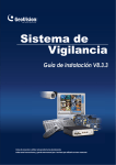
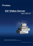
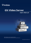
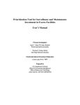
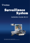
User Manual for VS Programs
E-Map Server
With the E-Map Server, you can create electronic maps for the cameras and I/O
devices connected to the GV-Video Server. Through web browser, you can monitor
the surveillance sites on the created E-Maps anywhere.
Installing E-Map Server
1. Insert the Software CD to your computer.
2. Locate and select the EMapServer folder.
3. Click the desired language folder, and double-click SETUP to install the program.
The E-Map Server Window
Go to Windows Start, point to Programs, select eMapServer, and then click E-Map
Server. This window appears.
1
2
3
4
5
6
7
1
The controls on the E-Map Server window:
No. Name
Description
1
2
3
4
5
6
7
Starts the E-Map Server.
Stops the E-Map Server.
Creates a new E-Map file.
Renames the E-Map file.
Deletes the E-Map file.
Refreshes the E-Map Server window.
Creates user accounts of the E-Map Server.
Start Service
Stop Service
New
Rename
Delete
Refresh
Accounts
Setting E-Map Server
Before starting the E-Map server, you have to create E-map files and user accounts.
To create an E-map file:
1. Click the New button. This dialog box appears.
2. Give a name for the E-map file, and click OK. The E-Map Editor window appears.
3. To create an E-Map, click the Add Map button on the toolbar. A New Map file
appears.
4. Double-click the New Map file, and click the Load Map button on the toolbar to
import a graphic file.
2
User Manual for VS Programs
5. To create a host, right-click on the Host View window, and select Add Video
Server.
6. Right-click the created New Host, and select Host Settings. This dialog box
appears.
7. Give the GV-Video Server a location name, and type its IP address (or domain
name). Keep the default VSS Port as 10000, or modify it to match that of GVVideo Server.
8. Click OK to save the settings.
9. Expand the created host folder. Drag and drop the icons of cameras and I/O
devices onto the imported E-Map.
10. Close the E-Map Editor. Click Yes when you are prompted to save the file.
3
To create a user account:
Click the Accounts button to create a user account that will use the server.
Remote Monitoring via E-Map Server
Via E-Map Server, you can monitor the surveillance sites on electronic maps from
any computer accessible to Internet.
1. Open the web browser, and type the address of the E-Map server.
2. After entering the valid user name and password for login, you will be prompted to
select the desired E-Map file (.emp file).
3. Click OK. The Remote E-Map window appears.
4. Click the Login button
. The Login dialog box appears.
5. Select the desired host(s), and click Login to access its videos and I/O devices.
For details on the Remote E-Map window, see Remote E-Map later.
4
User Manual for VS Programs
Remote E-Map
The Remote E-Map application allows you to monitor the surveillances sites on
electronic maps from any computer accessible to Internet. The application needs to
work with the E-Map server, so create E-maps files first with the E-Map server.
Note: There are two methods to connect to the E-Map server from the remote site.
One is to install the Remote E-Map application in the local computer first. The other
is via Internet. When you connect to the E-Map server, it will also download the
components of the Remote E-Map.
Installing Remote E-Map
1. Insert the Software CD to your computer.
2. Locate and select the RemoteEMap folder.
3. Double-click VSRemoteEMap to install the program.
Remote Monitoring with Remote E-Map
1. Double-click the Remote E-Map icon created on the desktop. The Login dialog
box appears.
2. Click the Edit button to enter the IP address of the E-Map server. Enter the valid
username and password. Click OK.
3. Select the desired E-Map file (.emp file), and click OK. The Remote E-Map
window appears.
4. Click the Login button
. The Login dialog box appears.
5. Select the desired host(s), and click Login to access its videos and I/O devices.
5
The Remote E-Map Window
4
9
4
8
1
2
3
4
4
4
5
4
6
4
7
The controls on the Remote E-Map window:
No. Name
Description
1
Login
2
Host Information
3
4
5
Previous
Home
Next
6
ViewLog
7
8
9
Configure
Camera Icon
Output Icon
Click to login host servers.
Click to view the information of incoming events upon motion
detection and I/O device trigger.
Click to go to the previous E-Map file.
Click to back to the top of the tree view.
Click to go to the next E-Map file.
Click to play back files, saved on the GV-Video Server, by
using the video player ViewLog.
Click to configure the Remote E-Map window.
Click to view the live video associated with that camera.
Click to force the output devices to be triggered manually.
6
User Manual for VS Programs
Logging in Different Hosts
1. Click the Login button on the Remote E-Map window. This dialog box appears.
2. Select the desired host name, and click Login. You will be prompted to enter the
valid username and password.
3. When the connection is established, the message “Login Complete” will appear.
Configuring the Remote E-Map Window
Click the Configure button on the Remote E-Map window. This dialog box appears.
7
[Download EMap files] Click to download E-Map files from the remote server to the
local PC. This option can reduce network load when you want to view E-Maps of
multiple hosts.
Use local EMap files: Once downloading E-Map files to the local PC, you can
use these E-Map files for connection.
Hide Tree List: Check to hide the tree list.
Enable DirectDraw: The DirectDraw is enabled by default. Some VGA cards
might not support DirectDraw and can produce distorted frames. In this case,
disable the feature.
[Motion] / [I/O Input]
Alert Sound: Check this option and assign a .wav file to alert the operator when
motion is detected or I/O devices are triggered.
Camera Blink, I/O Blink: When cameras or I/O devices are triggered, their icons
on the E-map flash. Uncheck this option if you don’t want to see the flashing
icons.
EMap Auto Popup: When cameras or I/O devices are triggered, the related map
will pop up on the screen instantly. Check this option and minimize the Remote
E-Map window for the application.
Show Event: When cameras or I/O devices are triggered, the trigger information
will register on the Host Information window.
8
User Manual for VS Programs
Viewing Host Information
The Host Information window registers the trigger information of cameras and I/O
devices. Click the Host Information button on the Remote E-Map window. This
dialog box appears.
9
Remote ViewLog
With the Remote ViewLog application, you can play back the files recorded at the
GV-Video Server over Internet.
Installing Remote ViewLog
1. Insert the Software CD to your computer.
2. Locate and select the RemoteViewLog folder.
3. Click the desired language folder, and double-click VSRemoteViewLog to install
the program.
Playing Back Video
For remote playback, the GV-Video Server must allow the access by enabling the
ViewLog Server first. For details, see GV-Video Server User’s Manual.
1. Run Remote ViewLog. This dialog box appears.
2. Type the GV-Video Server’s IP address, the login ID and password. Keep the
default port as 5552 or modify it if necessary.
3. In the Host Type field, select Video Server.
4. Click Connect to access the files of the GV-Video Server for playback.
10
User Manual for VS Programs
The ViewLog Window
1
2
3
4
5
6
7
8
9
10
11
17
16
15
14
13
12
18 19
The controls in the ViewLog window:
No Name
Description
1
Camera Name
Indicates the given camera name.
2
Camera View
Displays the playback video.
3
Date Tree
Displays date folders.
4
Video Event List
Displays video events within a certain date folder.
5
View Mode
Sets screen divisions: Single, Thumbnail, Quad or Multi
View.
6
Camera Select
Sets a desired camera for display.
7
Advance
Accesses the basic or advanced search, and reloads video
event list.
8
Normal
Displays the date tree and video event list.
9
Function Panel
Provides various settings for ViewLog.
11
10 Scroll Bar
Scrolls forward or backward of the playback video.
11 Audio Playback
Enables audio playback.
12 Playback Panel
Contains typical playback control buttons.
13 Function Icons
A highlighted icon indicates an enabled function. From left to
right are the A to B Mode, auto playing of next events, the
contrast and brightness function, the light enhancement and
equalization function, the sharpness and smoothness
function, the grayscale function, and reconnection to Remote
ViewLog.
14 Playback Speed
Indicates the playback speed. x 1 represents normal
playback speed.
15 Time Display
Indicates the time of the playback video.
16 Date Display
Indicates the date of the playback video.
17 Exit
Closes or minimizes the ViewLog window.
18 A to B Mode
Plays repeatedly the set frames A to B.
19
12
Frame by Frame /
Real Time
Plays back video frame by frame or on real time.
User Manual for VS Programs
Functional Panel
1
2
3
4
5
6
7
The controls in the Functional Panel:
No Name
Description
1
Effects
Adds effects to the images. The effect options include:
Sample, Contrast/Brightness, Light Enhancement,
Equalization, Sharpen, Smooth, Grayscale, Copy, Undo
to Prev. Action and Undo All Effects.
2
Save As AVI
Saves a video file as avi or exe format.
3
Save As Image
Saves a video image as bmp, jpg, gif, png, or tif format.
4
Print
Specifies various settings for printing.
5
Setting
Accesses system settings of ViewLog.
6
Tools
Brings up these options: Object Search, Advanced Log
Browser, Delete, Remote ViewLog Service, Address
Book, Full Screen and Tool Kit.
7
Backup
Backs up video files.
13
MultiView
With the MultiView application, you can monitor the surveillance sites over Internet.
Installing MultiView
1. Insert the Software CD to your computer.
2. Locate and select the MultiView folder.
3. Double-click DMVSMultiView to install the program.
Remote Monitoring with MultiView
With the MulitView application, you can monitor the surveillance sites from any
computer accessible to Internet.
1. Double-click the DMMuliView icon created on the desktop. The Login dialog box
appears.
14
User Manual for VS Programs
2. Click Edit. This dialog box appears.
3. Select Video Server, and type the IP address of the GV-Video Server. Keep VSS
Port as 10000, or modify it to match that of the GV-Video Server.
4. Click OK. The MultiView window will appear.
The MulitView Window
2
1
3
4
5
23 22 21 20 19 18 17
6
16
15
14 13
12
11
13
10
9
8
7
24
15
The controls in the MultiView Viewer:
No Name
Description
1
Monitoring Window
Displays live video.
2
Host Server Window
3
UPnP Device
Displays connected GV-Systems and their available
cameras.
Displays all hosts on the same LAN.
4
PTZ Control
Displays the PTZ control panel.
5
I/O Conrol
Displays the I/O control panel.
6
Channel Status
Indicates the general information of the selected channel.
7
ViewLog
Accesses Remote ViewLog.
8
Configure
Accesses system settings of the MultiView.
9
Edit Host
Adds, deletes or modifies GV-Systems.
10 Camera Status
11 Host Information
12 Zoom in and out
Displays the camera status of the connected GVSystems.
Displays the general information of the connected GVSystems.
Zooms in or out the selected channel.
13 Add/Remove
Channel
Adds or deletes the channels for video polling. Click the Add
or Remove Channel button and then click the desired channel
to add to or remove from the video polling.
14 Full Screen
Switches to a full screen view.
15 Video Polling
Rotates through the selected channels.
16 Screen Division
Sets the screen divisions for 4, 8 or 16.
17 Exit/Minimize
Closes or minimizes the MultiView window.
18 Speaker
Enables speaking to the remote GV-System.
19 Microphone
Enables live audio from the remote GV-System.
20 Stop
Terminates the connection to a GV-System.
21 Play
Establishes the connection to a GV-System.
22 Save
Saves live video.
23 Quality
Changes video resolution.
24 Snapshot
Takes a snapshot of the selected channel.
25 Save Camera to
Multiple Host
Saves the selected cameras to create a Multiple Host.
16