1
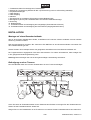
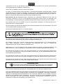
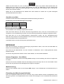
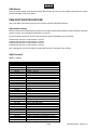
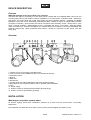
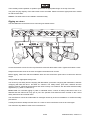
BEDIENUNGSANLEITUNG
USER MANUAL
LED QDF-Bar
with Soft Bag
Für weiteren Gebrauch aufbewahren!
Keep this manual for future needs!
© Copyright
Nachdruck verboten!
Reproduction prohibited!
MULTI-LANGUAGE-INSTRUCTIONS
Inhaltsverzeichnis / Table of contents
EINFÜHRUNG .................................................................................................................................................................... 3
Lieferumfang ................................................................................................................................................................... 3
SICHERHEITSHINWEISE .................................................................................................................................................. 3
BESTIMMUNGSGEMÄßE VERWENDUNG....................................................................................................................... 5
GERÄTEBESCHREIBUNG ................................................................................................................................................ 6
Features .......................................................................................................................................................................... 6
Geräteübersicht............................................................................................................................................................... 6
INSTALLATION .................................................................................................................................................................. 7
Montage auf einem Boxenhochständer........................................................................................................................... 7
Befestigung an einer Traverse ........................................................................................................................................ 7
DMX512-Ansteuerung..................................................................................................................................................... 9
Master/Slave-Betrieb....................................................................................................................................................... 9
Anschluss ans Netz....................................................................................................................................................... 10
BEDIENUNG..................................................................................................................................................................... 10
Internes Programm – Auto Modus ................................................................................................................................ 10
Musiksteuerung............................................................................................................................................................. 10
Einstellung der Mikrofonempfindlichkeit ........................................................................................................................ 10
DMX Modus .................................................................................................................................................................. 11
DMX-GESTEUERTER BETRIEB ..................................................................................................................................... 11
Spot Adressierung......................................................................................................................................................... 11
DMX-Protokoll ............................................................................................................................................................... 11
BETRIEB ÜBER FERNBEDIENUNG RC-2 (nicht im Lieferumfang enthalten)................................................................. 15
Fernbedienung über RC-2 Controller ............................................................................................................................ 15
REINIGUNG UND WARTUNG ......................................................................................................................................... 15
Sicherungswechsel ....................................................................................................................................................... 16
TECHNISCHE DATEN...................................................................................................................................................... 16
INTRODUCTION............................................................................................................................................................... 17
Delivery includes ........................................................................................................................................................... 17
SAFETY INSTRUCTIONS ................................................................................................................................................ 17
OPERATING DETERMINATIONS.................................................................................................................................... 19
DEVICE DESCRIPTION ................................................................................................................................................... 20
Features ........................................................................................................................................................................ 20
Overview ....................................................................................................................................................................... 20
INSTALLATION ................................................................................................................................................................ 20
Mounting on a speaker system stand............................................................................................................................ 20
Rigging on a truss ......................................................................................................................................................... 21
DMX512 control ............................................................................................................................................................ 22
Master/Slave operation ................................................................................................................................................. 23
Connection with the mains ............................................................................................................................................ 23
OPERATION..................................................................................................................................................................... 24
Internal Program – Auto Mode ...................................................................................................................................... 24
Sound control ................................................................................................................................................................ 24
Setting the Sound Sensitivity......................................................................................................................................... 24
DMX Mode .................................................................................................................................................................... 24
DMX-CONTROLLED OPERATION .................................................................................................................................. 24
Spot Addressing............................................................................................................................................................ 24
DMX-protocol ................................................................................................................................................................ 25
OPERATION VIA REMOTE CONTROL (not included in delivery) ................................................................................... 28
Remote control via RC-2 controller ............................................................................................................................... 28
CLEANING AND MAINTENANCE ................................................................................................................................... 28
Replacing the fuse ........................................................................................................................................................ 29
TECHNICAL SPECIFICATIONS....................................................................................................................................... 29
Diese Bedienungsanleitung gilt für die Artikelnummern: / This user manual is valid for the article numbers:
51918571, 51918572
Das neueste Update dieser Bedienungsanleitung finden Sie im Internet unter:
You can find the latest update of this user manual in the Internet under:
www.eurolite.de
2/29
00054291.DOC, Version 1.2
BEDIENUNGSANLEITUNG
LED QDF-Bar mit Tasche
ACHTUNG!
Gerät vor Feuchtigkeit und Nässe schützen!
Niemals das Gerät öffnen!
Lesen Sie vor der ersten Inbetriebnahme zur eigenen Sicherheit diese Bedienungsanleitung sorgfältig durch!
Alle Personen, die mit der Aufstellung, Inbetriebnahme, Bedienung, Wartung und Instandhaltung dieses
Gerätes zu tun haben, müssen
- entsprechend qualifiziert sein
- diese Bedienungsanleitung genau beachten
- die Bedienungsanleitung als Teil des Produkts betrachten
- die Bedienungsanleitung während der Lebensdauer des Produkts behalten
- die Bedienungsanleitung an jeden nachfolgenden Besitzer oder Benutzer des Produkts weitergeben
- sich die letzte Version der Anleitung im Internet herunter laden
EINFÜHRUNG
Wir freuen uns, dass Sie sich für einen EUROLITE LED QDF-Bar entschieden haben. Wenn Sie
nachfolgende Hinweise beachten, sind wir sicher, dass Sie lange Zeit Freude an Ihrem Kauf haben werden.
Lieferumfang
1
1
1
1
Gerät
Kaltgerätenetzleitung
Bedienungsanleitung
Tragetasche
Nehmen Sie den LED QDF-Bar aus der Verpackung.
SICHERHEITSHINWEISE
ACHTUNG!
Seien Sie besonders vorsichtig beim Umgang mit gefährlicher Netzspannung. Bei dieser Spannung können Sie einen lebensgefährlichen elektrischen Schlag erhalten!
Dieses Gerät hat das Werk in sicherheitstechnisch einwandfreiem Zustand verlassen. Um diesen Zustand zu
erhalten und einen gefahrlosen Betrieb sicherzustellen, muss der Anwender die Sicherheitshinweise und die
Warnvermerke unbedingt beachten, die in dieser Bedienungsanleitung enthalten sind.
3/29
00054291.DOC, Version 1.2
Unbedingt lesen:
Bei Schäden, die durch Nichtbeachtung der Anleitung verursacht werden, erlischt der Garantieanspruch. Für daraus resultierende Folgeschäden übernimmt der Hersteller keine Haftung.
Das Gerät darf nicht in Betrieb genommen werden, nachdem es von einem kalten in einen warmen Raum
gebracht wurde. Das dabei entstehende Kondenswasser kann unter Umständen Ihr Gerät zerstören. Lassen
Sie das Gerät solange uneingeschaltet, bis es Zimmertemperatur erreicht hat!
Bitte überprüfen Sie vor der ersten Inbetriebnahme, ob kein offensichtlicher Transportschaden vorliegt.
Sollten Sie Schäden an der Netzleitung oder am Gehäuse entdecken, nehmen Sie das Gerät nicht in Betrieb
und setzen sich bitte mit Ihrem Fachhändler in Verbindung.
Der Aufbau entspricht der Schutzklasse I. Der Netzstecker darf nur an eine Schutzkontakt-Steckdose
angeschlossen werden, deren Spannung und Frequenz mit dem Typenschild des Gerätes genau
übereinstimmt. Ungeeignete Spannungen und ungeeignete Steckdosen können zur Zerstörung des Gerätes
und zu tödlichen Stromschlägen führen.
Den Netzstecker immer als letztes einstecken. Der Netzstecker muss dabei gewaltfrei eingesetzt werden.
Achten Sie auf einen festen Sitz des Netzsteckers.
Lassen Sie die Netzleitung nicht mit anderen Kabeln in Kontakt kommen! Seien Sie vorsichtig beim Umgang
mit Netzleitungen und -anschlüssen. Fassen Sie diese Teile nie mit feuchten Händen an! Feuchte Hände
können tödliche Stromschläge zu Folge haben.
Netzleitungen nicht verändern, knicken, mechanisch belasten, durch Druck belasten, ziehen, erhitzen und
nicht in die Nähe von Hitze- oder Kältequellen bringen. Bei Missachtung kann es zu Beschädigungen der
Netzleitung, zu Brand oder zu tödlichen Stromschlägen kommen.
Die Kabeleinführung oder die Kupplung am Gerät dürfen nicht durch Zug belastet werden. Es muss stets
eine ausreichende Kabellänge zum Gerät hin vorhanden sein. Andernfalls kann das Kabel beschädigt
werden, was zu tödlichen Stromschlägen führen kann.
Achten Sie darauf, dass die Netzleitung nicht gequetscht oder durch scharfe Kanten beschädigt werden
kann. Überprüfen Sie das Gerät und die Netzleitung in regelmäßigen Abständen auf Beschädigungen.
Werden Verlängerungsleitungen verwendet muss sichergestellt werden, dass der Adernquerschnitt für die
benötigte Stromzufuhr des Gerätes zugelassen ist. Alle Warnhinweise für die Netzleitung gelten auch für
evtl. Verlängerungsleitungen.
Gerät bei Nichtbenutzung und vor jeder Reinigung vom Netz trennen! Fassen Sie dazu den Netzstecker an
der Griffläche an und ziehen Sie niemals an der Netzleitung! Ansonsten kann das Kabel und der Stecker
beschädigt werden was zu tödlichen Stromschlägen führen kann. Sind Stecker oder Geräteschalter, z. B.
durch Einbau nicht erreichbar, so muss netzseitig eine allpolige Abschaltung vorgenommen werden.
Wenn der Netzstecker oder das Gerät staubig ist, dann muss es außer Betrieb genommen werden, der
Stromkreis muss allpolig unterbrochen werden und das Gerät mit einem trockenen Tuch gereinigt werden.
Staub kann die Isolation reduzieren, was zu tödlichen Stromschlägen führen kann. Stärkere Verschmutzungen im und am Gerät dürfen nur von einem Fachmann beseitigt werden.
Es dürfen unter keinen Umständen Flüssigkeiten aller Art in Steckdosen, Steckverbindungen oder in
irgendwelche Geräteöffnungen oder Geräteritzen eindringen. Besteht der Verdacht, dass - auch nur
minimale - Flüssigkeit in das Gerät eingedrungen sein könnte, muss das Gerät sofort allpolig vom Netz
getrennt werden. Dies gilt auch, wenn das Gerät hoher Luftfeuchtigkeit ausgesetzt war. Auch wenn das
Gerät scheinbar noch funktioniert, muss es von einen Fachmann überprüft werden ob durch den Flüssigkeitseintritt eventuell Isolationen beeinträchtigt wurden. Reduzierte Isolationen können tödliche Stromschläge hervorrufen.
In das Gerät dürfen keine fremden Gegenstände gelangen. Dies gilt insbesondere für Metallteile. Sollten
auch nur kleinste Metallteile wie Heft- und Büroklammern oder gröbere Metallspäne in das Gerät gelangen,
so ist das Gerät sofort außer Betrieb zu nehmen und allpolig vom Netz zu trennen. Durch Metallteile
hervorgerufene Fehlfunktionen und Kurzschlüsse können tödliche Verletzungen zur Folge haben.
4/29
00054291.DOC, Version 1.2
GESUNDHEITSRISIKO!
Blicken Sie niemals direkt in die Lichtquelle, da bei empfindlichen Menschen u. U.
epileptische Anfälle ausgelöst werden können (gilt besonders für Epileptiker)!
Kinder und Laien vom Gerät fern halten!
Das Gerät darf niemals unbeaufsichtigt betrieben werden!
BESTIMMUNGSGEMÄßE VERWENDUNG
Bei diesem Gerät handelt es sich um einen Effektstrahler, mit dem sich dekorative Lichteffekte erzeugen
lassen. Dieses Produkt ist nur für den Anschluss an 230 V, 50 Hz Wechselspannung zugelassen und wurde
ausschließlich zur Verwendung in Innenräumen konzipiert.
Dieses Gerät ist für professionelle Anwendungen, z. B. auf Bühnen, in Diskotheken, Theatern etc.
vorgesehen.
Lichteffekte sind nicht für den Dauerbetrieb konzipiert. Denken Sie daran, dass konsequente Betriebspausen
die Lebensdauer des Gerätes erhöhen.
Vermeiden Sie Erschütterungen und jegliche Gewaltanwendung bei der Installation oder Inbetriebnahme des
Gerätes.
Achten Sie bei der Wahl des Installationsortes darauf, dass das Gerät nicht zu großer Hitze, Feuchtigkeit
und Staub ausgesetzt wird. Vergewissern Sie sich, dass keine Kabel frei herumliegen. Sie gefährden Ihre
eigene und die Sicherheit Dritter!
Das Gerät darf nicht in einer Umgebung eingesetzt oder gelagert werden, in der mit Spritzwasser, Regen,
Feuchtigkeit oder Nebel zu rechnen ist. Feuchtigkeit oder sehr hohe Luftfeuchtigkeit kann die Isolation
reduzieren und zu tödlichen Stromschlägen führen. Beim Einsatz von Nebelgeräten ist zu beachten, dass
das Gerät nie direkt dem Nebelstrahl ausgesetzt ist und mindestens 0,5 m von einem Nebelgerät entfernt
betrieben wird. Der Raum darf nur so stark mit Nebel gesättigt sein, dass eine gute Sichtweite von
mindestens 10 m besteht.
Die Umgebungstemperatur muss zwischen -5° C und +45° C liegen. Halten Sie das Gerät von direkter
Sonneneinstrahlung (auch beim Transport in geschlossenen Wägen) und Heizkörpern fern.
Die relative Luftfeuchte darf 50 % bei einer Umgebungstemperatur von 45° C nicht überschreiten.
Dieses Gerät darf nur in einer Höhenlage zwischen -20 und 2000 m über NN betrieben werden.
Verwenden Sie das Gerät nicht bei Gewitter. Überspannung könnte das Gerät zerstören. Das Gerät bei
Gewitter allpolig vom Netz trennen (Netzstecker ziehen).
- - -m
bezeichnet den Mindestabstand zu beleuchteten Gegenständen. Der Abstand
Das Bildzeichen
zwischen Lichtaustritt und der zu beleuchteten Fläche darf 0,1 Meter nicht unterschreiten!
Das Gerät darf nur über den Montagebügel installiert werden. Um eine gute Luftzirkulation zu gewährleisten,
muss um das Gerät ein Freiraum von mindestens 50 cm eingehalten werden.
Das Gehäuse darf niemals umliegende Gegenstände oder Flächen berühren!
Achten Sie bei der Montage, beim Abbau und bei der Durchführung von Servicearbeiten darauf, dass der
Bereich unterhalb des Montageortes abgesperrt ist.
Der Projektor ist immer mit einem geeigneten Sicherheitsfangseil zu sichern.
Die maximale Umgebungstemperatur Ta = 45° C darf niemals überschritten werden.
5/29
00054291.DOC, Version 1.2
Nehmen Sie das Gerät erst in Betrieb, nachdem Sie sich mit seinen Funktionen vertraut gemacht haben.
Lassen Sie das Gerät nicht von Personen bedienen, die sich nicht mit dem Gerät auskennen. Wenn Geräte
nicht mehr korrekt funktionieren, ist das meist das Ergebnis von unsachgemäßer Bedienung!
Reinigen Sie das Gerät niemals mit Lösungsmitteln oder scharfen Reinigungsmitteln, sondern verwenden
Sie ein weiches und angefeuchtetes Tuch.
Soll das Gerät transportiert werden, verwenden Sie bitte die Originalverpackung, um Transportschäden zu
vermeiden. Achten Sie bitte unbedingt darauf, dass das Gerät im Lieferzustand verpackt wird.
Beachten Sie bitte, dass eigenmächtige Veränderungen an dem Gerät aus Sicherheitsgründen verboten
sind.
Wird das Gerät anders verwendet als in dieser Bedienungsanleitung beschrieben, kann dies zu Schäden am
Produkt führen und der Garantieanspruch erlischt. Außerdem ist jede andere Verwendung mit Gefahren, wie
z. B. Kurzschluss, Brand, elektrischem Schlag, Abstürzen etc. verbunden.
GERÄTEBESCHREIBUNG
Features
DMX-LED-Scheinwerferset für einfache mobile Farbgestaltung!
Komplette Lichtanlage bestehend aus 4 LED-Spots und einem Querträger mit integrierter DMX-Steuereinheit
und Montageloch (36 mm) mit Feststellschraube zur Montage auf einem Trussing-System bzw. auf einem
Boxenhochständer • Adressierung und Einstellungen über Steuereinheit mit 4-stelliger LED-Anzeige und drei
Bedienknöpfe • Scheinwerfer schwenk- und neigbar • Per DMX kann jeder Spot einzeln angesteuert werden
• DMX-512 Steuerung über jeden handelsüblichen DMX-Controller möglich (belegt 6 Kanäle) • Musiksteuerung über eingebautes Mikrofon mit Empfindlichkeitsregler • Strobe Effekt • Auto Mode • Interne
Programme • Master/Slave Funktion • Bestückung mit 228 x 5 mm LEDs • Absolutes Leichtgewicht bestens
geeignet für mobilen Einsatz • Geeignet zur Montage auf einem Boxenhochständer (nicht inkl.) • Lieferung
erfolgt vormontiert in praktischer Tragetasche • Schwarz lackierte Metallausführung • Anschlussfertig über
Kaltgerätenetzleitung mit Schutzkontaktstecker
Geräteübersicht
1
2
3
5
6
7
8
DMX occupation:
1: Ground
2: Signal (-)
3: Signal (+)
Type: LED QDF-Bar with Soft Bag
Power supply: 230 V AC, 50 Hz ~
Power consumption: 50 W
Fuse: F 2 A, 250 V
LEDs: 228
0.1 m
4
9
10
Fuse: F 2 A, 250 V
F
Ta= 45° C TB= 60° C
MADE IN CHINA
www.eurolite.de
Remote control
Sensitivity
DMX IN
DMX OUT Microphone
MODE UP DOWN
1
Vor Gebrauch Anleitung lesen. Niemals direkt in die
Lichtquelle blicken (gilt speziell für Epileptiker)! Gerät vor
Feuchtigkeit und Nässe schützen! Vor dem
Sicherungswechsel allpolig vom Netz trennen! Wartungs
und Servicearbeiten nur durch autorisierten Fachhandel!
Read user manual before use. Never look directly into the
light source (especially meant for epileptics)! Keep away
from rain and moisture! Isolate luminaire from all poles of
the mains supply before opening the housing or repla-
Power supply: 230 V AC, 50 Hz ~
11
12
6/29
00054291.DOC, Version 1.2
1. Feststellschrauben für Montage über Theaterhaken
2. Buchse für Fernsteuerung EUROLITE RC-2 (Fernsteuerung nicht im Lieferumfang enthalten)
3. Empfindlichkeitsregler
4. DMX Eingang
5. DMX Ausgang
6. Mikrofon
7. Steuereinheit mit 4-stelliger LED-Anzeige und drei Bedienknöpfe
8. Montageloch (36 mm) mit Feststellschraube zur Boxenhochständer-Montage
9. Sicherung
10. Netzanschluss
11. Feststellschrauben zur Befestigung der Hängebügel (Schwenkbereich fixieren)
12. Feststellschrauben zur Befestigung der Scheinwerfer (Neigungswinkel fixieren)
INSTALLATION
Montage auf einem Boxenhochständer
Alle an einem Stativ angebrachten Geräte, Lichteffekte und Traversen müssen zusätzlich mit einer zweiten
Sicherung versehen werden!
Über den Montageloch montieren Sie zuerst den LED QDF-Bar an den Boxenhochständer und ziehen Sie
die Feststellschraube gut fest.
Setzen Sie dann eine Lautsprecherbox mit geeignetem Anbauflansch auf den Boxenhochständer auf.
Die Traglast darf den angegebenen Wert nicht überschreiten. Für weitere Informationen, bitte schlagen Sie
in der geeigneten Bedienungsanleitung nach.
Achtung: Beim Aufbringen der Last ist eine gleichmäßige Lastverteilung erforderlich.
Befestigung an einer Traverse
Der LED QDF-Bar lässt sich mit zwei Theaterhaken an einer Traverse befestigen.
DMX occupation:
1: Ground
2: Signal (-)
3: Signal (+)
Type: LED QDF-Bar with Soft Bag
Power supply: 230 V AC, 50 Hz ~
Power consumption: 30 W
Fuse: F 2 A, 250 V
LEDs: 228
0.1 m
Fuse: F 2 A, 250 V
F
Vor Gebrauch Anleitung lesen. Niemals direkt in die Lichtquelle
blicken (gilt speziell
für Epileptiker)! Gerät vor Feuchtigkeit und Nässe schützen!
Vor dem
Sicherungswechsel allpolig vom Netz trennen! Wartungs und
Servicearbeiten nur
durch autorisierten Fachhandel!
Read user
manual before use. Never look directly into the light source (especially
meant for
epileptics)! Keep away from rain and moisture! Isolate luminaire
from all poles of the
mains supply before opening the housing or repla-cing the fuse.
Maintenance and
service operations only by authorized dealers.
Ta= 45° C TB= 60° C
MADE IN CHINA
www.eurolite.de
Remote control
Sensitivity
DMX IN
DMX OUT
Microphone
MODE UP DOWN
Power supply: 230 V AC, 50 Hz ~
Lösen Sie dazu die Feststellschrauben an der Oberseite des Gerätes und bringen Sie die Theaterhaken an.
Ziehen Sie die Feststellschrauben wieder fest.
Hängen Sie nun die Theaterhaken in die Traverse ein und ziehen Sie die Feststellschrauben der Haken fest.
7/29
00054291.DOC, Version 1.2
Vergewissern Sie sich vor der Montage, dass die Montagefläche mindestens die 10-fache Punktbelastung
des Eigengewichtes der Installation aushalten kann.
Sichern Sie die Installation immer mit einem Sicherungsseil.
Es dürfen nur Sicherungsseile gemäß DIN 56927, Schnellverbindungsglieder gemäß DIN 56927, Schäkel
gemäß DIN EN 1677-1 und BGV C1 Kettbiner eingesetzt werden. Die Fangseile, Schnellverbindungsglieder,
Schäkel und Kettbiner müssen auf Grundlage der aktuellsten Arbeitsschutzbestimmungen (z. B. BGV C1,
BGI 810-3) ausreichend dimensioniert sein und korrekt angewendet werden.
Bitte beachten Sie: Bei Überkopfmontage in öffentlichen bzw. gewerblichen Bereichen ist eine Fülle von
Vorschriften zu beachten, die hier nur auszugsweise wiedergegeben werden können. Der Betreiber muss
sich selbständig um die Beschaffung der geltenden Sicherheitsvorschriften bemühen und diese einhalten!
Der Hersteller haftet nicht für Schäden, die durch unsachgemäße Installation und unzureichende Sicherheitsvorkehrungen verursacht werden!
Ein Sicherungsseil, das einmal der Belastung durch Absturz ausgesetzt war oder beschädigt ist, darf nicht
mehr als Sicherungsseil eingesetzt werden.
Der maximale Fallabstand darf 20 cm nicht überschreiten.
Die Aufhängevorrichtungen des Gerätes muss so gebaut und bemessen sein, dass sie 1 Stunde lang ohne
dauernde schädliche Deformierung das 10-fache der Nutzlast aushalten kann.
Die Installation muss immer mit einem zweiten geeigneten Sicherungselement (z. B. Stahlseil) erfolgen.
Diese zweite Aufhängung muss so beschaffen und angebracht sein, dass im Fehlerfall der
Hauptaufhängung kein Teil der Installation herabfallen kann.
Während des Auf-, Um- und Abbaus ist der unnötige Aufenthalt im Bereich von Bewegungsflächen, auf
Beleuchterbrücken, unter hochgelegenen Arbeitsplätzen sowie an sonstigen Gefahrbereichen verboten.
Der Unternehmer hat dafür zu sorgen, dass sicherheitstechnische und maschinentechnische Einrichtungen
vor der ersten Inbetriebnahme und nach wesentlichen Änderungen vor der Wiederinbetriebnahme durch
Sachverständige geprüft werden.
Der Unternehmer hat dafür zu sorgen, dass sicherheitstechnische und maschinentechnische Einrichtungen
mindestens alle vier Jahre durch einen Sachverständigen im Umfang der Abnahmeprüfung geprüft werden.
Der Unternehmer hat dafür zu sorgen, dass sicherheitstechnische und maschinentechnische Einrichtungen
mindestens einmal jährlich durch einen Sachkundigen geprüft werden.
BRANDGEFAHR!
Achten Sie bei der Installation des Gerätes bitte darauf, dass sich im Abstand
von mind. 0,5 m keine leicht entflammbaren Materialien (Deko, etc.) befinden.
Das Gerät sollte idealerweise außerhalb des Aufenthaltsbereiches von Personen installiert werden.
WICHTIG! ÜBERKOPFMONTAGE ERFORDERT EIN HOHES MAß AN ERFAHRUNG. Dies beinhaltet (aber
beschränkt sich nicht allein auf) Berechnungen zur Definition der Tragfähigkeit, verwendetes Installationsmaterial und regelmäßige Sicherheitsinspektionen des verwendeten Materials und des Gerätes. Versuchen
Sie niemals, die Installation selbst vorzunehmen, wenn Sie nicht über eine solche Qualifikation verfügen,
sondern beauftragen Sie einen professionellen Installateur. Unsachgemäße Installationen können zu
Verletzungen und/oder zur Beschädigung von Eigentum führen.
8/29
00054291.DOC, Version 1.2
Wenn das Gerät von der Decke oder hochliegenden Trägern etc. abgehängt werden soll, muss immer mit
Traversensystemen gearbeitet werden. Das Gerät darf niemals frei schwingend im Raum befestigt werden.
Achtung: Hängend installierte Geräte können beim Herabstürzen erhebliche Verletzungen verursachen!
Wenn Sie Zweifel an der Sicherheit einer möglichen Installationsform haben, installieren Sie das Gerät
NICHT!
LEBENSGEFAHR!
Vor der ersten Inbetriebnahme muss die Einrichtung durch einen Sachverständigen geprüft werden!
DMX512-Ansteuerung
Achten Sie darauf, dass die Adern der Datenleitung an keiner
Stelle miteinander in Kontakt treten. Die Geräte werden
ansonsten nicht bzw. nicht korrekt funktionieren.
Beachten Sie, dass die Startadresse abhängig vom verwendeten Controller ist.
Unbedingt Bedienungsanleitung des verwendeten Controllers beachten.
Die Verbindung zwischen Controller und Gerät sowie zwischen den einzelnen Geräten sollte mit einem
DMX-Kabel erfolgen. Die Steckverbindung geht über 3-polige XLR-Stecker und -Kupplungen.
Belegung der XLR-Verbindung:
Wenn Sie Controller mit dieser XLR-Belegung verwenden, können Sie den DMX-Ausgang des Controllers
direkt mit dem DMX-Eingang des ersten Gerätes der DMX-Kette verbinden. Sollen DMX-Controller mit
anderen XLR-Ausgängen angeschlossen werden, müssen Adapterkabel verwendet werden.
Aufbau einer seriellen DMX-Kette:
Schließen Sie den DMX-Ausgang des ersten Gerätes der Kette an den DMX-Eingang des nächsten Gerätes
an. Verbinden Sie immer einen Ausgang mit dem Eingang des nächsten Gerätes bis alle Geräte angeschlossen sind.
Achtung: Am letzten Gerät muss das DMX-Kabel durch einen Abschlusswiderstand abgeschlossen werden.
Dazu wird ein XLR-Stecker in den DMX-Ausgang am letzten Gerät gesteckt, bei dem zwischen Signal (–)
und Signal (+) ein 120- -Widerstand eingelötet ist.
Master/Slave-Betrieb
Im Master/Slave-Betrieb lassen sich mehrere Geräte synchronisieren, die dann von einem Mastergerät
gesteuert werden.
An der Rückseite des Gerätes befindet sich eine XLR-Einbaubuchse und ein XLR-Einbaustecker, über die
sich mehrere Geräte miteinander verbinden lassen.
9/29
00054291.DOC, Version 1.2
Wählen Sie das Gerät aus, das zur Steuerung der Effekte dienen soll. Dieses Gerät arbeitet dann als
Master-Gerät und steuert alle weiteren Slave-Geräte, die über ein DMX-Kabel mit dem Master-Gerät
verbunden werden. Stecken Sie das DMX-Kabel in die OUT-Buchse und verbinden Sie es mit dem INStecker des nächsten Gerätes.
Stellen Sie nun am Mastergerät den SOUND oder AUTO Modus ein. Stellen Sie an jedem Slavegerät
dieselbe DMX Adresse ein (001).
Anschluss ans Netz
Schließen Sie das Gerät über die beiliegende Netzanschlussleitung ans Netz an.
Die Belegung der Anschlussleitungen ist wie folgt:
Leitung
Braun
Blau
Gelb/Grün
Pin
Außenleiter
Neutralleiter
Schutzleiter
International
L
N
Der Schutzleiter muss unbedingt angeschlossen werden!
Wenn das Gerät direkt an das örtliche Stromnetz angeschlossen wird, muss eine Trennvorrichtung mit
mindestens 3 mm Kontaktöffnung an jedem Pol in die festverlegte elektrische Installation eingebaut werden.
Das Gerät darf nur an eine Elektroinstallation angeschlossen werden, die den VDE-Bestimmungen
DIN VDE 0100 entspricht. Die Hausinstallation muss mit einem Fehlerstromschutzschalter (RCD) mit 30 mA
Bemessungsdifferenzstrom ausgestattet sein.
Lichteffekte dürfen nicht über Dimmerpacks geschaltet werden.
BEDIENUNG
Wenn Sie das Gerät an die Spannungsversorgung angeschlossen haben, nimmt der LED QDF-BAR den
Betrieb auf und das Display leuchtet auf.
Das Gerät hat zwei Betriebsarten. Es kann entweder im Standalone- oder im DMX-gesteuerten Modus
betrieben werden.
Sie können den gewünschten Modus mit den Tasten MODE, UP oder DOWN auswählen:
Internes Programm – Auto Modus
Drücken Sie die MODE Taste bis das Display AUTO anzeigt um die Einstellung des internen Programmes
zu wählen.
Drücken Sie nochmal die MODE Taste bis das Display einen S—anzeigt. Über die UP oder DOWN Tasten
können Sie die gewünschte Geschwindigkeit des Programms eingeben.
Musiksteuerung
Drücken Sie die MODE Taste bis das Display SND anzeigt, um die Einstellungen der Musiksteuerung zu
wählen.
Einstellung der Mikrofonempfindlichkeit
Dank des eingebauten Mikrofones ist kein Controller nötig, und die Strahlen werden musikgesteuert durch
den Raum geworfen. Die Empfindlichkeit kann mit Hilfe des Drehreglers an der Geräterückseite beeinflusst
werden.
10/29
00054291.DOC, Version 1.2
DMX Modus
Drücken Sie die MODE Taste bis das Display 512 anzeigt. Über die UP oder DOWN Tasten können Sie die
gewünschte DMX Adresse eingeben.
DMX-GESTEUERTER BETRIEB
Über Ihren DMX-Controller können Sie die einzelnen Geräte individuell ansteuern.
Spot Adressierung
Dieses Gerät ist mit 4 Scheinwerfern bestückt, die jeweils mit den DIP-Schalter auf der Rückseite adressiert
werden müssen, um einwandfrei funktionieren zu können.
Die DIP-Schalter wurden ab Werk korrekt eingestellt. Anbei die Einstellungen als Hinweis:
Scheinwerfer Nummer 1: DIP-Schalter 1 auf ON.
Scheinwerfer Nummer 2: DIP-Schalter 2 auf ON.
Scheinwerfer Nummer 3: DIP-Schalter 3 auf ON.
Scheinwerfer Nummer 4: DIP-Schalter 4 auf ON.
Eine Verdoppelung der DIP-Schalter Einstellungen führt zur Fehlfunktion des Gerätes.
DMX-Protokoll
Kanal 1 – Spot 1
Wert:
0-10
11-16
17-22
23-28
29-34
35-40
41-46
47-52
53-58
59-64
65-70
71-76
77-82
83-88
89-94
95-100
101-106
107-112
113-118
119-124
125-130
131-136
137-142
143-148
149-154
155-160
161-172
167-172
173-178
179-184
185-190
Funktion:
Aus
Gruppe 1 von weiß
Gruppe 2 von weiß
Gruppe 3 von weiß
Gruppe 1 von rot
Gruppe 2 von rot
Gruppe 3 von rot
Gruppe 1 von grün
Gruppe 2 von grün
Gruppe 3 von grün
Gruppe 1 von blau
Gruppe 2 von blau
Gruppe 3 von blau
alles weiß
alles rot
alles grün
alles blau
alles rot und alles grün
alles rot und alles blau
alles grün und alles blau
alles rot, alles grün und alles blau
alles rot und alles weiß
alles grün und alles weiß
alles blau und alles weiß
Gruppe 1 von blau und alles weiß
Gruppe 2 von blau und alles rot
Gruppe 3 von blau und grün
Gruppe 1 von blau und Gruppe 3 von rot
Gruppe 2 von blau und Gruppe 2 von rot
Gruppe 3 von blau und Gruppe 1 von rot
Gruppe 1 von grün und Gruppe 3 von weiß
11/29
00054291.DOC, Version 1.2
191-196
197-202
203-208
209-214
215-220
221-255
Gruppe 2 von grün und Gruppe 2 von weiß
Gruppe 3 von grün und Gruppe 1 von weiß
Gruppe 1 von blau, Gruppe 3 von grün,
Gruppe 1 von rot, und Gruppe 3 von weiß
Gruppe 2 blau, Gruppe 2 von grün, Gruppe
2 von rot, und Gruppe 2 von weiß
Gruppe 3 von blau, Gruppe 1 von grün,
Gruppe 3 von rot, Gruppe 1 von weiß
alles weiß, alles rot, alles grün und alles blau
Kanal 2 – Spot 2
Wert:
0-10
11-16
17-22
23-28
29-34
35-40
41-46
47-52
53-58
59-64
65-70
71-76
77-82
83-88
89-94
95-100
101-106
107-112
113-118
119-124
125-130
131-136
137-142
143-148
149-154
155-160
161-172
167-172
173-178
179-184
185-190
191-196
197-202
203-208
209-214
215-220
221-255
Funktion:
Aus
Gruppe 1 von weiß
Gruppe 2 von weiß
Gruppe 3 von weiß
Gruppe 1 von rot
Gruppe 2 von rot
Gruppe 3 von rot
Gruppe 1 von grün
Gruppe 2 von grün
Gruppe 3 von grün
Gruppe 1 von blau
Gruppe 2 von blau
Gruppe 3 von blau
alles weiß
alles rot
alles grün
alles blau
alles rot und alles grün
alles rot und alles blau
alles grün und alles blau
alles rot, alles grün und alles blau
alles rot und alles weiß
alles grün und alles weiß
alles blau und alles weiß
Gruppe 1 von blau und alles weiß
Gruppe 2 von blau und alles rot
Gruppe 3 von blau und grün
Gruppe 1 von blau und Gruppe 3 von rot
Gruppe 2 von blau und Gruppe 2 von rot
Gruppe 3 von blau und Gruppe 1 von rot
Gruppe 1 von grün und Gruppe 3 von weiß
Gruppe 2 von grün und Gruppe 2 von weiß
Gruppe 3 von grün und Gruppe 1 von weiß
Gruppe 1 von blau, Gruppe 3 von grün,
Gruppe 1 von rot, und Gruppe 3 von weiß
Gruppe 2 blau, Gruppe 2 von grün, Gruppe
2 von rot, und Gruppe 2 von weiß
Gruppe 3 von blau, Gruppe 1 von grün,
Gruppe 3 von rot, Gruppe 1 von weiß
alles weiß, alles rot, alles grün und alles blau
12/29
00054291.DOC, Version 1.2
Kanal 3 – Spot 3
Wert:
0-10
11-16
17-22
23-28
29-34
35-40
41-46
47-52
53-58
59-64
65-70
71-76
77-82
83-88
89-94
95-100
101-106
107-112
113-118
119-124
125-130
131-136
137-142
143-148
149-154
155-160
161-172
167-172
173-178
179-184
185-190
191-196
197-202
203-208
209-214
215-220
221-255
Funktion:
Aus
Gruppe 1 von weiß
Gruppe 2 von weiß
Gruppe 3 von weiß
Gruppe 1 von rot
Gruppe 2 von rot
Gruppe 3 von rot
Gruppe 1 von grün
Gruppe 2 von grün
Gruppe 3 von grün
Gruppe 1 von blau
Gruppe 2 von blau
Gruppe 3 von blau
alles weiß
alles rot
alles grün
alles blau
alles rot und alles grün
alles rot und alles blau
alles grün und alles blau
alles rot, alles grün und alles blau
alles rot und alles weiß
alles grün und alles weiß
alles blau und alles weiß
Gruppe 1 von blau und alles weiß
Gruppe 2 von blau und alles rot
Gruppe 3 von blau und grün
Gruppe 1 von blau und Gruppe 3 von rot
Gruppe 2 von blau und Gruppe 2 von rot
Gruppe 3 von blau und Gruppe 1 von rot
Gruppe 1 von grün und Gruppe 3 von weiß
Gruppe 2 von grün und Gruppe 2 von weiß
Gruppe 3 von grün und Gruppe 1 von weiß
Gruppe 1 von blau, Gruppe 3 von grün,
Gruppe 1 von rot, und Gruppe 3 von weiß
Gruppe 2 blau, Gruppe 2 von grün, Gruppe
2 von rot, und Gruppe 2 von weiß
Gruppe 3 von blau, Gruppe 1 von grün,
Gruppe 3 von rot, Gruppe 1 von weiß
alles weiß, alles rot, alles grün und alles blau
Kanal 4 – Spot 4
Wert:
0-10
11-16
17-22
23-28
29-34
35-40
41-46
47-52
53-58
59-64
65-70
71-76
Funktion:
Aus
Gruppe 1 von weiß
Gruppe 2 von weiß
Gruppe 3 von weiß
Gruppe 1 von rot
Gruppe 2 von rot
Gruppe 3 von rot
Gruppe 1 von grün
Gruppe 2 von grün
Gruppe 3 von grün
Gruppe 1 von blau
Gruppe 2 von blau
13/29
00054291.DOC, Version 1.2
77-82
83-88
89-94
95-100
101-106
107-112
113-118
119-124
125-130
131-136
137-142
143-148
149-154
155-160
161-172
167-172
173-178
179-184
185-190
191-196
197-202
203-208
209-214
215-220
221-255
Gruppe 3 von blau
alles weiß
alles rot
alles grün
alles blau
alles rot und alles grün
alles rot und alles blau
alles grün und alles blau
alles rot, alles grün und alles blau
alles rot und alles weiß
alles grün und alles weiß
alles blau und alles weiß
Gruppe 1 von blau und alles weiß
Gruppe 2 von blau und alles rot
Gruppe 3 von blau und grün
Gruppe 1 von blau und Gruppe 3 von rot
Gruppe 2 von blau und Gruppe 2 von rot
Gruppe 3 von blau und Gruppe 1 von rot
Gruppe 1 von grün und Gruppe 3 von weiß
Gruppe 2 von grün und Gruppe 2 von weiß
Gruppe 3 von grün und Gruppe 1 von weiß
Gruppe 1 von blau, Gruppe 3 von grün,
Gruppe 1 von rot, und Gruppe 3 von weiß
Gruppe 2 blau, Gruppe 2 von grün, Gruppe
2 von rot, und Gruppe 2 von weiß
Gruppe 3 von blau, Gruppe 1 von grün,
Gruppe 3 von rot, Gruppe 1 von weiß
alles weiß, alles rot, alles grün und alles blau
Kanal 5 – Strobe
Wert:
000 – 010
011 - 255
Funktion:
Aus
Flash, mit zunehmender Geschwindigkeit
Kanal 6 – Interne Programme, Auto Modus, Musikgesteuerter Modus
Wert:
000 – 010
011 – 036
037 – 062
063 – 088
098 – 114
115 – 130
131 – 156
157 – 182
183 – 208
209 – 250
251 – 255
Funktion:
Aus
Programm 1
Programm 2
Programm 3
Programm 4
Programm 5
Programm 6
Programm 7
Programm 8
Auto Modus: Interne Programme
Musikgesteuert
14/29
00054291.DOC, Version 1.2
BETRIEB ÜBER FERNBEDIENUNG RC-2 (nicht im Lieferumfang enthalten)
Schließen Sie die Fernbedienung mit der LED QDF-Bar über die Verbindungsleitung mit StereoKlinkenstecker an.
Fernbedienung über RC-2 Controller
Nach dem Anschließen schaltet das Gerät in den musikgesteuerten Modus, unabhängig von dem was am
Display angezeigt wird.
1. Drücken Sie die SPEED-Taste, um die gewünschte Reaktionszeit der Musiksteuerung einzustellen:
- Wenn die entsprechende LED blinkt, ist die Reaktionszeit der Musiksteuerung schnell.
- Wenn die entsprechende LED leuchtet, ist die Reaktionszeit mittelschnell.
- Wenn die entsprechende LED aus ist, ist die Reaktionszeit langsam.
2. Drücken Sie die PROGRAMS/STROBE-Taste, um die Muster der internen Programme zu wechseln.
Die Strobe Funktion ist bei diesem Gerät nicht vorhanden.
3. Drücken Sie die BLACKOUT-Taste, um den Blackout einzustellen
Im Blackout Modus leuchtet die entsprechende LED.
REINIGUNG UND WARTUNG
Der Unternehmer hat dafür zu sorgen, dass sicherheitstechnische und maschinentechnische Einrichtungen
mindestens alle vier Jahre durch einen Sachverständigen im Umfang der Abnahmeprüfung geprüft werden.
Der Unternehmer hat dafür zu sorgen, dass sicherheitstechnische und maschinentechnische Einrichtungen
mindestens einmal jährlich durch einen Sachkundigen geprüft werden.
Dabei muss unter anderem auf folgende Punkte besonders geachtet werden:
1) Alle Schrauben, mit denen das Gerät oder Geräteteile montiert sind, müssen fest sitzen und dürfen nicht
korrodiert sein.
2) An Gehäuse, Befestigungen und Montageort (Decke, Abhängung, Traverse) dürfen keine Verformungen
sichtbar sein.
3) Die elektrischen Anschlussleitungen dürfen keinerlei Beschädigungen, Materialalterung (z.B. poröse
Leitungen) oder Ablagerungen aufweisen. Weitere, auf den jeweiligen Einsatzort und die Nutzung
abgestimmte Vorschriften werden vom sachkundigen Installateur beachtet und Sicherheitsmängel
behoben.
LEBENSGEFAHR!
Vor Wartungsarbeiten unbedingt allpolig vom Netz trennen!
Das Gerät sollte regelmäßig von Verunreinigungen wie Staub usw. gereinigt werden. Verwenden Sie zur
Reinigung ein fusselfreies, angefeuchtetes Tuch. Auf keinen Fall Alkohol oder irgendwelche Lösungsmittel
zur Reinigung verwenden!
Im Geräteinneren befinden sich außer der Sicherung keine zu wartenden Teile. Wartungs- und Servicearbeiten sind ausschließlich dem autorisierten Fachhandel vorbehalten!
15/29
00054291.DOC, Version 1.2
Sicherungswechsel
Wenn die Feinsicherung des Gerätes defekt ist, darf diese nur durch eine Sicherung gleichen Typs ersetzt
werden.
Vor dem Sicherungswechsel ist das Gerät allpolig von der Netzspannung zu trennen (Netzstecker
ziehen).
Vorgehensweise:
Schritt 1: Öffnen Sie den Sicherungshalter an der Geräterückseite mit einem passenden Schraubendreher.
Schritt 2: Entfernen Sie die defekte Sicherung aus dem Sicherungshalter.
Schritt 3: Setzen Sie die neue Sicherung in den Sicherungshalter ein.
Schritt 4: Setzen Sie den Sicherungshalter wieder im Gehäuse ein.
Sollten einmal Ersatzteile benötigt werden, verwenden Sie bitte nur Originalersatzteile.
Wenn die Anschlussleitung dieses Gerätes beschädigt wird, muss sie durch eine besondere Anschlussleitung ersetzt werden, die von Ihrem Fachhändler erhältlich ist.
Sollten Sie noch weitere Fragen haben, steht Ihnen Ihr Fachhändler jederzeit gerne zur Verfügung.
TECHNISCHE DATEN
Spannungsversorgung:
Gesamtanschlusswert:
Anzahl der Kanäle:
DMX 512-Anschluss:
Musiksteuerung:
Maximale Umgebungstemperatur Ta:
Max. Leuchtentemperatur im Beharrungszustand TB:
Mindestabstand zu enflammbaren Oberflächen:
Mindestabstand zum angestrahlten Objekt:
Sicherung:
LED-Typ:
Anzahl der LEDs:
Abstrahlwinkel:
Maße (LxBxH):
Gewicht:
230 V AC, 50 Hz ~
50 W
6
3-pol. XLR
über eingebautes Mikrofon
45° C
60° C
0,50 m
0,10 m
F 2 A, 250V
5 mm
228
23°
860 x 210 x 260 mm
5 kg
Zubehör:
EUROLITE RC-2 Fernsteuerung 10m
EUROLITE TH-50 Theaterhaken, silber
EUROLITE TH-50S Theaterhaken, schwarz
Best.-Nr.:
51918558
58000650
58000651
Bitte beachten Sie: Technische Änderungen ohne vorherige Ankündigung und Irrtum vorbehalten.
01.03.2011 ©
16/29
00054291.DOC, Version 1.2
USER MANUAL
LED QDF-Bar with Soft Bag
CAUTION!
Keep this device away from rain and moisture!
Never open the housing!
For your own safety, please read this user manual carefully before you initially start-up.
Every person involved with the installation, operation and maintenance of this device has to
- be qualilfied
- follow the instructions of this manual
- consider this manual to be part of the total product
- keep this manual for the entire service life of the product
- pass this manual on to every further owner or user of the product
- download the latest version of the user manual from the Internet
INTRODUCTION
Thank you for having chosen a EUROLITE LED QDF-Bar. If you follow the instructions given in this manual,
we are sure that you will enjoy this device for a long period of time.
Delivery includes
1
1
1
1
Device
IEC Power cable
User manual
Transport bag
Unpack your LED QDF-Bar.
SAFETY INSTRUCTIONS
CAUTION!
Be careful with your operations. With a dangerous voltage you can suffer a dangerous
electric shock when touching the wires!
This device has left our premises in absolutely perfect condition. In order to maintain this condition and to
ensure a safe operation, it is absolutely necessary for the user to follow the safety instructions and warning
notes written in this user manual.
Important:
Damages caused by the disregard of this user manual are not subject to warranty. The dealer
will not accept liability for any resulting defects or problems.
17/29
00054291.DOC, Version 1.2
If the device has been exposed to drastic temperature fluctuation (e.g. after transportation), do not switch it
on immediately. The arising condensation water might damage your device. Leave the device switched off
until it has reached room temperature.
Please make sure that there are no obvious transport damages. Should you notice any damages on the A/C
connection cable or on the casing, do not take the device into operation and immediately consult your local
dealer.
This device falls under protection-class I. The power plug must only be plugged into a protection class I
outlet. The voltage and frequency must exactly be the same as stated on the device. Wrong voltages or
power outlets can lead to the destruction of the device and to mortal electrical shock.
Always plug in the power plug last. The power plug must always be inserted without force. Make sure that
the plug is tightly connected with the outlet.
Never let the power-cord come into contact with other cables! Handle the power-cord and all connections
with the mains with particular caution! Never touch them with wet hands, as this could lead to mortal
electrical shock.
Never modify, bend, strain mechanically, put pressure on, pull or heat up the power cord. Never operate next
to sources of heat or cold. Disregard can lead to power cord damages, fire or mortal electrical shock.
The cable insert or the female part in the device must never be strained. There must always be sufficient
cable to the device. Otherwise, the cable may be damaged which may lead to mortal damage.
Make sure that the power-cord is never crimped or damaged by sharp edges. Check the device and the
power-cord from time to time.
If extension cords are used, make sure that the core diameter is sufficient for the required power
consumption of the device. All warnings concerning the power cords are also valid for possible extension
cords.
Always disconnect from the mains, when the device is not in use or before cleaning it. Only handle the
power-cord by the plug. Never pull out the plug by tugging the power-cord. Otherwise, the cable or plug can
be damaged leading to mortal electrical shock. If the power plug or the power switch is not accessible, the
device must be disconnected via the mains.
If the power plug or the device is dusty, the device must be taken out of operation, disconnected and then be
cleaned with a dry cloth. Dust can reduce the insulation which may lead to mortal electrical shock. More
severe dirt in and at the device should only be removed by a specialist.
There must never enter any liquid into power outlets, extension cords or any holes in the housing of the
device. If you suppose that also a minimal amount of liquid may have entered the device, it must immediately
be disconnected. This is also valid, if the device was exposed to high humidity. Also if the device is still
running, the device must be checked by a specialist if the liquid has reduced any insulation. Reduced
insulation can cause mortal electrical shock.
There must never be any objects entering into the device. This is especially valid for metal parts. If any metal
parts like staples or coarse metal chips enter into the device, the device must be taken out of operation and
disconnected immediately. Malfunction or short-circuits caused by metal parts may cause mortal injuries.
HEALTH HAZARD!
Never look directly into the light source, as sensitive persons may suffer an
epileptic shock (especially meant for epileptics)!
Keep away children and amateurs!
Never leave this device running unattended.
18/29
00054291.DOC, Version 1.2
OPERATING DETERMINATIONS
This device is a lighting effect for creating decorative effects. This product is only allowed to be operated with
an alternating voltage of 230 V, 50 Hz and was designed for indoor use only.
This device is designed for professional use, e.g. on stages, in discotheques, theatres etc.
Lighting effects are not designed for permanent operation. Consistent operation breaks will ensure that the
device will serve you for a long time without defects.
Do not shake the device. Avoid brute force when installing or operating the device.
When choosing the installation-spot, please make sure that the device is not exposed to extreme heat,
moisture or dust. There should not be any cables lying around. You endanger your own and the safety of
others!
This device must never be operated or stockpiled in sourroundings where splash water, rain, moisture or fog
may harm the device. Moisture or very high humidity can reduce the insulation and lead to mortal electrical
shocks. When using smoke machines, make sure that the device is never exposed to the direct smoke jet
and is installed in a distance of 0.5 meters between smoke machine and device. The room must only be
saturated with an amount of smoke that the visibility will always be more than 10 meters.
The ambient temperature must always be between -5° C and +45° C. Keep away from direct insulation
(particularly in cars) and heaters.
The relative humidity must not exceed 50 % with an ambient temperature of 45° C.
This device must only be operated in an altitude between -20 and 2000 m over NN.
Never use the device during thunderstorms. Over voltage could destroy the device. Always disconnect the
device during thunderstorms.
- - -m
determines the minimum distance from lighted objects. The minimum distance
The symbol
between light-output and the illuminated surface must be more than 0.1 meters.
This device is only allowed for an installation via the mounting bracket. In order to safeguard sufficient
ventilation, leave 50 cm of free space around the device.
The housing must never touch surrounding surfaces or objects.
Make sure that the area below the installation place is blocked when rigging, derigging or servicing the
fixture.
Always fix the fixture with an appropriate safety bond.
The maximum ambient temperature Ta = 45° C must never be exceeded.
Operate the device only after having become familiarized with its functions. Do not permit operation by
persons not qualified for operating the device. Most damages are the result of unprofessional operation!
Never use solvents or aggressive detergents in order to clean the device! Rather use a soft and damp cloth.
Please use the original packaging if the device is to be transported. Make sure that you pack the device in
the original state.
Please consider that unauthorized modifications on the device are forbidden due to safety reasons!
If this device will be operated in any way different to the one described in this manual, the product may suffer
damages and the guarantee becomes void. Furthermore, any other operation may lead to dangers like shortcircuit, burns, electric shock, crash etc.
19/29
00054291.DOC, Version 1.2
DEVICE DESCRIPTION
Features
DMX LED spotlight set for easy mobile color creativity!
Complete LED light set consisting of 4 LED spots and a crossbar with an integrated DMX control unit and
mounting hole (36 mm) with fixation screw for installation on a truss system or speaker stand • Addressing
and setting via control panel with 4-digit LED display and three operating buttons • Pivotable and tiltable
spotlights • Each spot can be individually controlled via DMX • DMX-512 control via regular DMX-controller
(occupies 6 channels) • Sound-control via built-in microphone with sensitivity control • Strobe effect • Auto
mode • Internal programs • Master/Slave function • Equipped with 228 x 5 mm LEDs • Ultra-light ideally
suited for mobile use • Suited for installation on a speaker stand (not included) • Comes pre-assembled with
practical transport bag • Black lacquered metal version • Ready for connection via IEC power cord with
safety plug
Overview
1
2
3
5
6
7
8
DMX occupation:
1: Ground
2: Signal (-)
3: Signal (+)
Type: LED QDF-Bar with Soft Bag
Power supply: 230 V AC, 50 Hz ~
Power consumption: 50 W
Fuse: F 2 A, 250 V
LEDs: 228
0.1 m
4
9
10
Fuse: F 2 A, 250 V
F
Ta= 45° C TB= 60° C
MADE IN CHINA
www.eurolite.de
Remote control
Sensitivity
DMX IN
DMX OUT Microphone
MODE UP DOWN
1
Vor Gebrauch Anleitung lesen. Niemals direkt in die
Lichtquelle blicken (gilt speziell für Epileptiker)! Gerät vor
Feuchtigkeit und Nässe schützen! Vor dem
Sicherungswechsel allpolig vom Netz trennen! Wartungs
und Servicearbeiten nur durch autorisierten Fachhandel!
Read user manual before use. Never look directly into the
light source (especially meant for epileptics)! Keep away
from rain and moisture! Isolate luminaire from all poles of
the mains supply before opening the housing or repla-
Power supply: 230 V AC, 50 Hz ~
11
12
1. Fixation screws for mounting via theatre hooks
2. Jack for remote control EUROLITE RC-2 (not included in delivery)
3. Sensitivity control
4. DMX In
5. DMX Out
6. Microphone
7. Control panel with 4-digit LED display and three operating buttons
8. Mounting hole (36 mm) with fixation screw for speaker stand installation
9. Fuse
10. Power supply
11. Fixation screws for hanging bracket fixation (pivoting range)
12. Fixation screws for spot fixation (tilt angle)
INSTALLATION
Mounting on a speaker system stand
All devices, lighting effects and crossbeams attached on a stand must be secured with a secondary
attachment!
First install the LED QDF-Bar on the tube via the mounting hole and tighten the fixation screw.
20/29
00054291.DOC, Version 1.2
Then carefully install a speaker or speaker-system with an appropriate flange on the top of the tube.
The given carrying capacity of the stand must not be exceeded. Please consult the appropriate user manual
for further information.
Caution: The loads have to be installed in a balanced way.
Rigging on a truss
The LED QDF-Bar can be fixed onto a truss using two theatre hooks.
DMX occupation:
1: Ground
2: Signal (-)
3: Signal (+)
Type: LED QDF-Bar with Soft Bag
Power supply: 230 V AC, 50 Hz ~
Power consumption: 30 W
Fuse: F 2 A, 250 V
LEDs: 228
0.1 m
Fuse: F 2 A, 250 V
F
Vor Gebrauch Anleitung lesen. Niemals direkt in die Lichtquelle
blicken (gilt speziell
für Epileptiker)! Gerät vor Feuchtigkeit und Nässe schützen!
Vor dem
Sicherungswechsel allpolig vom Netz trennen! Wartungs und
Servicearbeiten nur
durch autorisierten Fachhandel!
Read user
manual before use. Never look directly into the light source (especially
meant for
epileptics)! Keep away from rain and moisture! Isolate luminaire
from all poles of the
mains supply before opening the housing or repla-cing the fuse.
Maintenance and
service operations only by authorized dealers.
Ta= 45° C TB= 60° C
MADE IN CHINA
www.eurolite.de
Remote control
Sensitivity
DMX IN
DMX OUT
Microphone
MODE
UP DOWN
Power supply: 230 V AC, 50 Hz ~
Loosen the fixation screws from the top of the device and afix the theatre hooks. Tighten the fixation screws
Suspend the theatre hooks in the truss and tighten the theatre hook screws.
Before rigging, make sure that the installation area can hold a minimum point load of 10 times the device's
weight.
Always install an appropriate safety bond.
You must only use safety bonds complying with DIN 56927, quick links complying with DIN 56927, shackles
complying with DIN EN 1677-1 and BGV C1 carbines. The safety bonds, quick links, shackles and the
carbines must be sufficiently dimensioned and used correctly in accordance with the latest industrial safety
regulations (e. g. BGV C1, BGI 810-3).
Please note: for overhead rigging in public or industrial areas, a series of safety instructions have to be
followed that this manual can only give in part. The operator must therefore inform himself on the current
safety instructions and consider them.
The manufacturer cannot be made liable for damages caused by incorrect installations or insufficient safety
precautions!
A safety bond which already held the strain of a crash or which is defective must not be used again.
The maximum drop distance must never exceed 20 cm.
21/29
00054291.DOC, Version 1.2
DANGER TO LIFE!
Please consider the EN 60598-2-17and the respective national standards during the installation!
The installation must only be carried out by an authorized dealer!
The installation of the device has to be built and constructed in a way that it can hold 10 times the weight for
1 hour without any harming deformation.
The installation must always be secured with an appropriate secondary safety element (e.g. steel rope). This
secondary safety attachment must be constructed in a way that no part of the installation can fall down if the
main attachment fails.
When rigging, derigging or servicing the device staying in the area below the installation place, on bridges,
under high working places and other endangered areas is forbidden.
The operator has to make sure that safety-relating and machine-technical installations are approved by an
expert before taking into operation for the first time and after changes before taking into operation another
time.
The operator has to make sure that safety-relating and machine-technical installations are approved by an
expert after every four year in the course of an acceptance test.
The operator has to make sure that safety-relating and machine-technical installations are approved by a
skilled person once a year.
DANGER OF FIRE!
When installing the device, make sure there is no highly-inflammable
material (decoration articles, etc.) within a distance of min. 0.5 m.
The device should be installed outside areas where persons may walk by or be seated.
IMPORTANT! OVERHEAD RIGGING REQUIRES EXTENSIVE EXPERIENCE, including (but not limited to)
calculating working load limits, installation material being used, and periodic safety inspection of all
installation material and the device. If you lack these qualifications, do not attempt the installation yourself,
but instead use a professional structural rigger. Improper installation can result in bodily injury and or
damage to property.
If the device shall be lowered from the ceiling or high joists, professional trussing systems have to be used.
The device must never be fixed swinging freely in the room.
Caution: Devices in hanging installations may cause severe injuries when crashing down! If you have
doubts concerning the safety of a possible installation, do NOT install the device!
DANGER TO LIFE!
Before taking into operation for the first time, the installation has to be approved by an expert!
DMX512 control
The wires must not come into contact with each other, otherwise
the devices will not work at all, or will not work properly.
Please note, the starting address depends upon which controller is being used.
22/29
00054291.DOC, Version 1.2
Only use a DMX cable and 3-pin XLR plugs and connectors in order to connect the controller with the fixture
or one fixture with another.
Occupation of the XLR connection:
If you are using controllers with this occupation, you can connect the DMX output of the controller directly
with the DMX input of the first device in the DMX chain. If you wish to connect DMX controllers with other
XLR outputs, you need to use adapter cables.
Building a serial DMX chain:
Connect the DMX output of the first device in the DMX chain with the DMX input of the next device. Always
connect one output with the input of the next device until all devices are connected.
Caution: At the last fixture, the DMX cable has to be terminated. Plug the terminator with a 120
between Signal (–) and Signal (+) in the DMX output of the last fixture.
resistor
Master/Slave operation
The master/slave operation enables that several devices can be synchronized and controlled by one master
device.
On the rear panel of the device you can find an XLR jack and an XLR plug, which can be used for
connecting several devices.
Choose the device which is to control the effects. This device then works as master device and controls all
other slave devices, which are to be connected to the master device via a DMX-cable. Connect the OUT jack
with the IN plug of the next device.
Set the Master device to SOUND or AUTO mode and set each Slave device to the same DMX address
(001).
Connection with the mains
Connect the device to the mains with the enclosed power supply cable.
The occupation of the connection-cables is as follows:
Cable
Brown
Blue
Yellow/Green
Pin
Live
Neutral
Earth
International
L
N
The earth has to be connected!
If the device will be directly connected with the local power supply network, a disconnection switch with a
minimum opening of 3 mm at every pole has to be included in the permanent electrical installation.
The device must only be connected with an electric installation carried out in compliance with the IECstandards. The electric installation must be equipped with a Residual Current Device (RCD) with a maximum
fault current of 30 mA.
23/29
00054291.DOC, Version 1.2
Lighting effects must not be connected to dimming-packs.
OPERATION
After you connected the spot to the mains, the EUROLITE LED QDF-Bar starts running and the display lights
up.
The device has two operating modes. It can be operated in Stand-Alone or in DMX-controlled mode.
You can choose the desired mode via the buttons MENU, UP and DOWN:
Internal Program – Auto Mode
Press the MODE button until the display shows AUTO to set the internal program.
Press the MODE button again until the display shows an S—. Via the UP or DOWN buttons you can set the
desired speed of the program.
Sound control
Press the MODE button until the display shows SND to set the Sound Control Mode.
Setting the Sound Sensitivity
You can do without a controller as the device features a built-in microphone, which provides automatic sound
control. You can adjust the sensitivity with the rotary-control on the rearpanel.
DMX Mode
Press the MODE button until the display shows 512. Via the UP or DOWN buttons you can set the desired
DMX address.
DMX-CONTROLLED OPERATION
You can control the spots individually via your DMX-controller.
Spot Addressing
This devices comes with 4 spots, which must be addressed individually with the DIP-switches on the rear, in
order to ensure proper functioning.
The DIP-switches were pre-addressed in the factory. Below the settings for future reference:
Spot Number 1: DIP-switch 1 on ON.
Spot Number 2: DIP-switch 2 on ON.
Spot Number 3: DIP-switch 3 on ON.
Spot Number 4: DIP-switch 4 on ON.
A duplication will cause malfunction of the device.
24/29
00054291.DOC, Version 1.2
DMX-protocol
Channel 1 – Spot 1
Value:
0-10
11-16
17-22
23-28
29-34
35-40
41-46
47-52
53-58
59-64
65-70
71-76
77-82
83-88
89-94
95-100
101-106
107-112
113-118
119-124
125-130
131-136
137-142
143-148
149-154
155-160
161-172
167-172
173-178
179-184
185-190
191-196
197-202
203-208
209-214
215-220
221-255
Function:
No function
group 1 of white
group 2 of white
group 3 of white
group 1 of red
group 2 of red
group 3 of red
group 1 of green
group 2 of green
group 3 of green
group 1 of blue
group 2 of blue
group 3 of blue
all white
all red
all green
all blue
all red and all green
all red and all blue
all green and all blue
all red, all green and all blue
all red and all white
all green and all white
all blue and all white
group 1 of blue and all white
group 2 of blue and all red
group 3 of blue and green
group 1 of blue and group 3 of red
group 2 of blue and group 2 of red
group 3 of blue and group 1 of red
group 1 of green and group 3 of white
group 2 of green and group 2 of white
group 3 of green and group 1 of white
group 1 of blue, group 3 of green, group 1
of red, and group 3 of white
group 2 blue, group 2 of green, group 2 of
red, and group 2 of white
group 3 of blue, group 1 of green, group 3
of red, group 1 of white
all white, all red, all green and all blue
Channel 2 – Spot 2
Value:
0-10
11-16
17-22
23-28
29-34
35-40
41-46
47-52
53-58
59-64
65-70
71-76
77-82
83-88
89-94
95-100
101-106
Function:
No function
group 1 of white
group 2 of white
group 3 of white
group 1 of red
group 2 of red
group 3 of red
group 1 of green
group 2 of green
group 3 of green
group 1 of blue
group 2 of blue
group 3 of blue
all white
all red
all green
all blue
25/29
00054291.DOC, Version 1.2
107-112
113-118
119-124
125-130
131-136
137-142
143-148
149-154
155-160
161-172
167-172
173-178
179-184
185-190
191-196
197-202
203-208
209-214
215-220
221-255
all red and all green
all red and all blue
all green and all blue
all red, all green and all blue
all red and all white
all green and all white
all blue and all white
group 1 of blue and all white
group 2 of blue and all red
group 3 of blue and green
group 1 of blue and group 3 of red
group 2 of blue and group 2 of red
group 3 of blue and group 1 of red
group 1 of green and group 3 of white
group 2 of green and group 2 of white
group 3 of green and group 1 of white
group 1 of blue, group 3 of green, group 1
of red, and group 3 of white
group 2 blue, group 2 of green, group 2 of
red, and group 2 of white
group 3 of blue, group 1 of green, group 3
of red, group 1 of white
all white, all red, all green and all blue
Channel 3 – Spot 3
Value:
0-10
11-16
17-22
23-28
29-34
35-40
41-46
47-52
53-58
59-64
65-70
71-76
77-82
83-88
89-94
95-100
101-106
107-112
113-118
119-124
125-130
131-136
137-142
143-148
149-154
155-160
161-172
167-172
173-178
179-184
185-190
191-196
197-202
203-208
209-214
215-220
221-255
Function:
No function
group 1 of white
group 2 of white
group 3 of white
group 1 of red
group 2 of red
group 3 of red
group 1 of green
group 2 of green
group 3 of green
group 1 of blue
group 2 of blue
group 3 of blue
all white
all red
all green
all blue
all red and all green
all red and all blue
all green and all blue
all red, all green and all blue
all red and all white
all green and all white
all blue and all white
group 1 of blue and all white
group 2 of blue and all red
group 3 of blue and green
group 1 of blue and group 3 of red
group 2 of blue and group 2 of red
group 3 of blue and group 1 of red
group 1 of green and group 3 of white
group 2 of green and group 2 of white
group 3 of green and group 1 of white
group 1 of blue, group 3 of green, group 1
of red, and group 3 of white
group 2 blue, group 2 of green, group 2 of
red, and group 2 of white
group 3 of blue, group 1 of green, group 3
of red, group 1 of white
all white, all red, all green and all blue
26/29
00054291.DOC, Version 1.2
Channel 4 – Spot 4
Value:
0-10
11-16
17-22
23-28
29-34
35-40
41-46
47-52
53-58
59-64
65-70
71-76
77-82
83-88
89-94
95-100
101-106
107-112
113-118
119-124
125-130
131-136
137-142
143-148
149-154
155-160
161-172
167-172
173-178
179-184
185-190
191-196
197-202
203-208
209-214
215-220
221-255
Function:
No function
group 1 of white
group 2 of white
group 3 of white
group 1 of red
group 2 of red
group 3 of red
group 1 of green
group 2 of green
group 3 of green
group 1 of blue
group 2 of blue
group 3 of blue
all white
all red
all green
all blue
all red and all green
all red and all blue
all green and all blue
all red, all green and all blue
all red and all white
all green and all white
all blue and all white
group 1 of blue and all white
group 2 of blue and all red
group 3 of blue and green
group 1 of blue and group 3 of red
group 2 of blue and group 2 of red
group 3 of blue and group 1 of red
group 1 of green and group 3 of white
group 2 of green and group 2 of white
group 3 of green and group 1 of white
group 1 of blue, group 3 of green, group 1
of red, and group 3 of white
group 2 blue, group 2 of green, group 2 of
red, and group 2 of white
group 3 of blue, group 1 of green, group 3
of red, group 1 of white
all white, all red, all green and all blue
Channel 5 – Strobe
Value:
000 – 010
011 - 255
Function:
Off
Flash, with increasing speed
Channel 6 – Internal Programs, Auto Mode, Sound Controlled Mode
Value:
000 – 010
011 – 036
037 – 062
063 – 088
098 – 114
115 – 130
131 – 156
157 – 182
183 – 208
209 – 250
251 – 255
Function:
Off
Program 1
Program 2
Program 3
Program 4
Program 5
Program 6
Program 7
Program 8
Auto Mode: Internal programs
Sound Controlled Mode
27/29
00054291.DOC, Version 1.2
OPERATION VIA REMOTE CONTROL (not included in delivery)
Connect the remote control with the LED QDF-Bar device via the connection cable with stereo jack.
Remote control via RC-2 controller
After connection, the device switches into sound control mode, irrespective of what is shown on the display.
1.Press the SPEED-button in order to adjust the desired reaction time for sound control:
- When the corresponding LED flashes, it is in fast mode
- When the corresponding LED is permanently on, it is in mid mode
- When the corresponding LED stays off, it is in slow mode
2. Press the PROGRAMS/STROBE-button in order to change the patterns of the internal programs.
The Strobe function is not available.
3. Press the BLACKOUT-button, in order to set Blackout.
The corresponding LED is permanently on in Blackout mode.
CLEANING AND MAINTENANCE
The operator has to make sure that safety-relating and machine-technical installations are inspected by an
expert after every four years in the course of an acceptance test.
The operator has to make sure that safety-relating and machine-technical installations are inspected by a
skilled person once a year.
The following points have to be considered during the inspection:
1) All screws used for installing the devices or parts of the device have to be tightly connected and must not
be corroded.
2) There must not be any deformations on housings, fixations and installation spots (ceiling, suspension,
trussing).
3) The electric power supply cables must not show any damages, material fatigue (e.g. porous cables) or
sediments. Further instructions depending on the installation spot and usage have to be adhered by a
skilled installer and any safety problems have to be removed.
DANGER TO LIFE!
Disconnect from mains before starting maintenance operation!
We recommend a frequent cleaning of the device. Please use a soft lint-free and moistened cloth. Never use
alcohol or solvents!
There are no serviceable parts inside the device except for the fuse. Maintenance and service operations are
only to be carried out by authorized dealers.
28/29
00054291.DOC, Version 1.2
Replacing the fuse
If the fine-wire fuse of the device fuses, only replace the fuse by a fuse of same type and rating.
Before replacing the fuse, unplug mains lead.
Procedure:
Step 1: Open the fuseholder on the rear panel with a fitting screwdriver.
Step 2: Remove the old fuse from the fuseholder.
Step 3: Install the new fuse in the fuseholder.
Step 4: Replace the fuseholder in the housing.
Should you need any spare parts, please use genuine parts.
If the power supply cable of this device becomes damaged, it has to be replaced by a special power supply
cable available at your dealer.
Should you have further questions, please contact your dealer.
TECHNICAL SPECIFICATIONS
Power supply:
Power consumption:
Number of DMX channels:
DMX-512 connection:
Sound-control:
Maximum ambient temperature Ta:
Maximum housing temperature TB (steady state):
Min.distance from flammable surfaces:
Min.distance to lighted object:
Fuse:
LED-Type:
Number of LEDs:
Beam angle:
Dimensions (LxWxH):
Weight:
230 V AC, 50 Hz ~
50 W
6
3-pin XLR
via built-in microphone
45° C
60° C
0.50 m
0.10 m
F 2 A, 250V
5 mm
228
23°
860 x 210 x 260 mm
5 kg
Accessories:
EUROLITE RC-2 remote control 10m
EUROLITE TH-50 Theatre hook, silver
EUROLITE TH-50S Theatre hook, black
No.
51918558
58000650
58000651
Please note: Every information is subject to change without prior notice. 01.03.2011 ©
29/29
00054291.DOC, Version 1.2