1
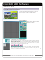
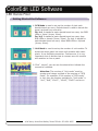
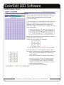
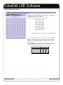
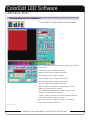
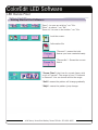
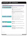
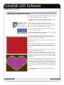
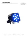
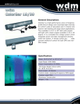
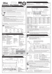
wdmlighting.com
ColorEdit LED Software
LED Dance Floor
Color Edit Software
USER MANUAL
WDM LIGHTING 2603 OAK LAWN AVE., STE. 120, DALLAS, TX 75219
PAGE 01
4016 Harry Hines Blvd Dallas, Texas 75219 • 972-650-1855
wdmlighting.com
ColorEdit LED Software
LED Dance Floor
Installing Software:
Set up the color edit software
1. Double click on the Color Edit Set-up .exe file to
begin installation.
2. Follow the steps in the Installation window to
install the Color Edit Software.
3. After successful installation, find the Color Edit
Shortcut icon the desktop and double click to
start the software.
WDM LIGHTING 2603 OAK LAWN AVE., STE. 120, DALLAS, TX 75219
PAGE 02
4016 Harry Hines Blvd Dallas, Texas 75219 • 972-650-1855
wdmlighting.com
ColorEdit LED Software
LED Dance Floor
Getting Started the Software:
1. When first starting the software, a new window will appear. Click the “NEW” button.
2. Main Window:
After clicking “New” the Main
Window will apper.
3. Setting the “Grid” of the dance floor:
One grid represents one pixel. You can choose the number of grids by editing the
number of “Col” and “Sel”.
“Col” represents the number of rows in horizontal while the “Sel” represents the
number of lines in vertical. The range for both “Col” and “Sel” are from “1~20”, which
means that the max total pixels can be 20x20=400.
Once confirmed the number of “Col” and “Sel”, click “Select”. Then the operational
area is chosen as white color area. If you need to re-choose the area, just click
“Clear” and re-do above-mentioned steps.
PAGE 03
4016 Harry Hines Blvd Dallas, Texas 75219 • 972-650-1855
wdmlighting.com
ColorEdit LED Software
LED Dance Floor
Getting Started the Software:
4. PCB Mode is used to set up the number of pixel each
decode board can carry. Decode board is used to decode the
signal received from controller.
For 1x1, it stands for each decode board can carry 1pc RGB
LEDs or 1pixel (1rows, 1lines).
For 2x2, it stands for each decode board can carry 4pcs
RGB LEDs or 4pixels (2rows, 2lines). For 4x4, it stands for
each decode board can carry 16pcs RGB LEDs or 16pixels
(4rows, 4lines).
5. Unit Mode is used to set up the number of unit module. To
divide the whole panel into some unit modules with same
pixels. It can facilitate connection. Furthermore, it is very
important since it decides how to connect one unit module
with another to form a panel.
6. Click “ Layout”, you can see the sheet which indicate the
connection methods.
Attention: The number of “Unit mode” must be
greater and integer multiple of the number of “PCB
mode”. For example: If the number of “PCB mode”
is 4x4, then the number available for “Unit mode” is
“4x4”, “8x8”, “12x12”, “16x16”, “20x20” and so on.
WDM LIGHTING 2603 OAK LAWN AVE., STE. 120, DALLAS, TX 75219
PAGE 04
4016 Harry Hines Blvd Dallas, Texas 75219 • 972-650-1855
wdmlighting.com
ColorEdit LED Software
LED Dance Floor
Getting Started the Software:
Given a LED panel with total 256pixels (16rows,
16lines), each decode board carry 16pixels
(PCB mode: 4x4)
A. If the number of “Unit mode” is “8*8”, then the
panel is divided into 4 unit modules with same
64pixels. 4pcs decode boards are required for
each unit module. The connection method of modules is as follow:
Within each Unit Module, the connection method
of decode board is as follow
(Take 1st Unit module for example):
b. If the number of “Unit mode” is “16*8”, then
the panel is divided into 2 unit modules with same
128pixels. 8pcs decode boards are required for
each unit module.
The connection method of modules is as follow:
Within each Unit Module, the connection method
of decode board is as follow
(Take 1st Unit module for example):
WDM LIGHTING 2603 OAK LAWN AVE., STE. 120, DALLAS, TX 75219
PAGE 05
4016 Harry Hines Blvd Dallas, Texas 75219 • 972-650-1855
wdmlighting.com
ColorEdit LED Software
LED Dance Floor
Getting Started the Software:
Within each Unit Module, the connection method
of decode board is as follow
(Take 1st Unit module for example):
C. If the number of “Unit mode” is “4*4”, then the
panel is divided into 16 unit modules with same
16pixels. 1pc decode board is required for each
unit module.
The connection method of Unit modules and the
decode boards is the same and as follow:
1st Unit Module
2nd
3rd
4th
5th
6th
7th
8th
9th
10th
11th
12th
th
th
16th
th
13
14
15
WDM LIGHTING 2603 OAK LAWN AVE., STE. 120, DALLAS, TX 75219
PAGE 06
4016 Harry Hines Blvd Dallas, Texas 75219 • 972-650-1855
wdmlighting.com
ColorEdit LED Software
LED Dance Floor
Getting Started the Software:
7. Press “Edit” to enter a New Product Window.
“Fill” and “Fill all” means fill the whole screen with one background color.
“Left” means move the pattern leftward.
“Right” means move the pattern rightward.
“UP” means move the pattern upward.
“Down” means move the pattern downward.
“Flip (H)” means flip the pattern horizontally.
“Flip (V)” means flip the pattern vertically.
“Col 1” stands for the position of initial row you could
choose for words, letters or number.
“Sel 1” stands for the position of initial lines you could
choose for words, letters or number.
“16x16”, “20x20”, “24x24” and “32x32” stand for font size.
“Text” can be letters, numbers or signs.
Click “Text” after you type the content, it can display.
“CHN” can be Chinese characters.
PAGE 07
4016 Harry Hines Blvd Dallas, Texas 75219 • 972-650-1855
wdmlighting.com
ColorEdit LED Software
LED Dance Floor
Getting Started the Software:
“Open”: to open an existing “.cor” file.
“Save”: to save a “.cor” file.
“Save As”: to save to be another “.cor” file.
Lock the screen.
Information file.
“Frames1”: means the total
frames you have created already.
“Frames No.”: Shows the current
frame.
“Frame Time”: the time for current frame, with
a unit of “second”. The range is from “0.1second
to 5second”. You can choose within the range.
“Soft”: means the pattern will change gradually.
“Skip”: means the pattern jump change.
PAGE 08
4016 Harry Hines Blvd Dallas, Texas 75219 • 972-650-1855
wdmlighting.com
ColorEdit LED Software
LED Dance Floor
Getting Started the Software:
“Goto”: means to return to one frame you would
like to review or edit.
“Back”: means to return to previous frame.
“Next”: means to go to next frame.
“Insert”: means to insert one new frame. If you
find you omit one frame between 5th and 6th
frame, go to the 6th frame, click “insert” to create
a new frame.
“Delete”: means to delete current frame.
“Copy”: copy the whole pattern in current frame.
“Paste”: paste the copied frame to any frames.
“Undo”: to cancel previous action.
“View”: to display the pattern of current frame.
“PCB Mode”: same as what described in the
fourth items.
“Unit Mode”: same as what described in the fifth
items.
“Layout”: you can check the connecting methods
of unit modules.
“Download”: Once you finish the programs,
click “Download” to download the programs to the
main controller.
PAGE 09
4016 Harry Hines Blvd Dallas, Texas 75219 • 972-650-1855
wdmlighting.com
ColorEdit LED Software
LED Dance Floor
Exporting a Programed Show:
Before you download the finished programs to main controller, some jobs require to do the follows:
1) Power the main controller with an AC18V power supply,
use USB wire to connect main controller with PC.
2) After step1, set up drivers of main controller.
For one PC, you are only required to set up once. To run
this driver, your PC configuration must be Windows 2000 or
Windows XP or more advanced systems edition.
3) Click “ Download” then “send”, you can download the
programs to main controller.
4) Connect main controller to panel with the wire, the panel
will run automatically with the program.
5) Please be noted that AC18V power supply is only required for main controller when download programs from
PC, unnecessary during work time.
6) If some mistakes occur, please seek help from below possible solutions:
A. Click “Download” first, then “send”, no “connect succeed”
but “linking…” and “please check connect and power”. It
may be caused by bad power connection or loose USB connection.
B. Click “Download” first, then “send”, it said “connect succeed”, but only download maybe
0.3% then failed. At the same time, the red light of main
controller turns on. It is certain that something is wrong
with the main controller. Maybe the AC18V power supply is
not well connected to main controller, or the power supply is
burned-out.
C. It also may cause mistakes if the program file is too big
to download. It always fails during download and the red
light of main controller also turn on at the same time. So if
the frames of the program are too many and the total pixels are large, user should be noted that the file size of the
“.cor” should be less than 512K, if not, download also will
fail.
If any problem, please contact your local distributors for
detail instructions.
PAGE 10
4016 Harry Hines Blvd Dallas, Texas 75219 • 972-650-1855