1
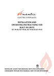
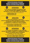
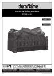
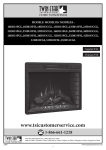
ELECTRIC BUILDERS BOX
Electric Builder Box
INSTALLATION GUIDE
MODEL NUMBERS:
36EB110-GRT, 36EB111-GRC
36EB220-GRT, 36EB221-GRC
CONSUMER SAFETY INFORMATION
PLEASE READ THIS MANUAL BEFORE USING THIS APPLIANCE
WARNING
IF THE INFORMATION IN THIS MANUAL IS NOT FOLLOWED,
AN ELECTRIC SHOCK OR FIRE MAY RESULT CAUSING PROPERTY
DAMAGE, PERSONAL INJURY OR LOSS OF LIFE.
DO NOT STORE OR USE GASOLINE OR OTHER FLAMMABLE
VAPORS AND LIQUIDS IN THE VICINITY OF THIS
OR ANY OTHER APPLIANCE.
Thank you and congratulations on your purchase of a Classic Flame electric
builder box. Please read the installation instructions before installing and
operating this appliance.
IMPORTANT: Read all instructions and warnings carefully before using.
Failure to follow these instructions may result in a possible electric shock,
fire hazard and/ or injury and will void the warranty.
For Customer Service:
www.tsicustomerservice.com
1-866-661-1218
E-1
Twin-Star International, Inc.
Delray Beach, FL 33445
U.S.A.
Made in China
Printed in China
©2013,Twin-Star International,Inc.
LISTINGS AND CODE APPROVALS
THE BUILDERS BOX SERIES HAS BEEN TESTED AND APPROVED IN ACCORDANCE WITH
CSA AND UL STANDARDS FOR FIXED AND LOCATION DEDICATED ELECTRIC ROOM HEATERS.
MODEL SPECIFICATIONS
VOLTAGE
MODEL NUMBER
DESCRIPTION
36EB110-GRT
36” TRADITIONAL
120
36EB220-GRT
36” TRADITIONAL
208/240
36EB111-GRC
36” CONTEMPORARY
120
36EB221-GRC
36” CONTEMPORARY
208/240
RATED POWER
WATTS
1440
2100/2800
1440
2100/2800
BTU
AMPS
4400
12
6700/8900 10.1/11.7
4400
12
6700/8900 10.1/11.7
WARNING
THE INSTALLATION OF THE BUILDER BOX MUST COMPLY WITH THE APPLICABLE
LOCAL AND / OR NATIONAL ELECTRICAL CODES AND UTILITY REQUIREMENTS.
THIS INSTALLATION SHOULD BE ENTRUSTED TO ONLY QUALIFIED
PERSONNNEL WHERE REQUIRED BY LAW.
INSTALLATION OVERVIEW
(Please read all instructions and user manual before installation)
Section 1.) Prepare product for installation.
Section 2.) Rough in framing following the recommended dimensions.
Section 3.) Recommended power supply wire specifications.
Section 4.) Mount the unit.
Section 5.) 120V wiring instructions.
Section 6.) 208/240V wiring instructions.
Section 7.) Install control box.
Section 8.) Check & test.
Section 9.) Electrical wiring diagram.
E-2
SECTION 1: PREPARATION
1.) Open the master carton, stone box , and wall mounted control box and make sure you have
all the parts listed. Remove the parts from the cartons and put them in a safe location
( see figure 1.)
Figure 1
3
Sign Wire
DOWN
UP
FLAME
TIMRER
Control Box with bracket
Remote Control
Power Cord
(Only for 36EB110-GRT)
36EB110-GRT
36EB220-GRT
Sign Wire
DOWN
UP
FLAME
TIMRER
DOWN
UP
LIGHT EFFECTS
Control Box with bracket
Remote Control
Stones
Fireglass
36EB111-GRC
36EB221-GRC
Power Cord
(Only for 36EB111-GRC)
E-3
2.) Unscrew 2 screws on the side edge of the frame (Fig. 2). Securely holding the frame lift up
and pull away from the unit to remove the frame. Do not remove the protective plastic
film at this time. Place the frame in a safe place( see figure 2.)
Figure 2
3
STEP 1
UNSCREW 2
SCREWS
STEP 2
LIFT FRONT PANEL
36EB110-GRT
36EB220-GRT
STEP 1
UNSCREW 2
SCREWS
36EB111-GRC
36EB221-GRC
E-4
STEP 2
LIFT FRONT PANEL
SECTION
2: FRAMING
Section 1: Framing
This fireplace is a zero clearance design. No combustibles can be placed on the top surface
of the fireplace. Combustibles may be installed to the edge of the unit. Insulation and vapor
barrier should be placed a minimum of 2 inches from the unit. Build the framing according
to the specifications shown in the below table & figure 3.
MODEL
36EB110-GRT
36EB220-GRT
36EB111-GRC
36EB221-GRC
A
B
8”
35”
C
23.8”
D
24”
E
18”
F
G
H
36”
33.5”
34.7”
I
J
23.6”
7.8”
K
L
M
51”
36”
36”
Framing Specification: Figure 3
H
L
D
E
G
I
K
F
J
Section 3: Recommended Power Supply Wire
Specifications
For 36EB110-GRT & 36EB111-GRC installations use three non-metallic
sheathed cables with ground wire for the power supply. Use the appropriate wires to
meet local and national electrical codes for rated power consumption.
For 36EB220-GRT & 36EB221-GRC installations use four non-metallic
sheathed cables with ground wire for the incoming power supply. Use the appropriate
wires to meet local and national electrical codes for rated power consumption.
Recommended Wire and Fusing Requirements
Use appropriate wire to meet local and national electrical codes for rated power
consumption. All wire gauges should be 12 gauge solid wires with a dedicated 15 amp
breaker for 120 volts. For 208/240 volts Builders Box models use two dedicated
15 amp breakers.
Allow at least 8 in of service cable for connecting power supply wire to junction box on
fireplace insert when installing before finishing wall. Allow up to 4 feet of service cable
for connecting power supply wire to junction box on fireplace insert after finishing wall.
The control box is supplied with a six meter long cable.
E-5
M
SECTION 4: MOUNTING
Install Method:
1.) Remove front frame (see figure 2).
2.) Remove the screws holding side panels and then remove the side panels (see figure 4 & 5).
3.) Insert the builders box into the opening in the framing.
Figure 4: Mounting Tab Location
36EB111-GRC
36EB221-GRC
36EB110-GRT
36EB220-GRT
Figure 5: Wall and Mounting Tabs
36EB110-GRT
36EB220-GRT
36EB111-GRC
36EB221-GRC
E-6
4.) Install the builders box using 4pcs screws from the inside of the builder box (see figure 6 & 7).
5.) Remount the side panels.
6.) Place the stones as desired.(Only for 36EB111-GRC & 36EB221-GRC )
7.) Remount the front frame.
Figure 6: Mounting Tab Location
Place sto
nes here.
36EB110-GRT
36EB220-GRT
36EB111-GRC
36EB221-GRC
Figure 7: Wall and Mounting Tabs
E-7
SECTION 5: 120V WIRING INSTRUCTIONS
1.) Loosen the screw securing the junction box cover and remove the cover.
2.) Pull the power supply wires through the hole in the cover.
3.) Pull out the 4 wires marked L, N, G, S from the junction box on the side of the
builder box.
4.) Connect the black L wire from the unit to the black L from the power supply.
5.) Connect the white N wire from the unit to the white N from power supply.
6.) Connect the green ground G wire from the unit to the ground from the power supply.
7.) Plug the S wire connector into the provided sign wire.
8.) Ensure that all connections are tight.
9.) Secure all the wiring with wire-caps, then insert into the junction box.
10.) Remount the junction box cover (see figure 8 & 9.)
Note: 36EB110-GRT & 36EB111-GRC will only run on 120 volt operation.
Figure 8
120 V
Configration
Min. 14AWG WIRE FROM
POWER SUPPLY (NOT SUPPLIED)
Min. 14AWG WIRE
FROM POWER SUPPLY
(NOT SUPPLIED)
CONTROL
E-8
SECTION 6: 208/240V WIRING INSTRUCTIONS
1.) Loosen the screw securing the junction box cover and remove the cover.
2.) Pull the power supply wires through the hole in the cover.
3.) Pull out the 5 wires marked L1, L2, N, G, S from the junction box on the side of the
builder box.
4.) Connect the black L1 wire and red L2 from the unit to the two dedicated 15 amp
lines from the power supply.
5.) Connect the white N wire from the unit to the white N from power supply.
6.) Connect the green ground G wire from the unit to the ground from the power supply.
7.) Plug the S wire connector into the provided sign wire.
8.) Ensure that all connections are tight.
9.) Secure all the wiring with wire-caps, then insert into the junction box.
10.) Remount the junction box cover (see figure 8 & 9.)
Note: 36EB220-GRT & 36EB221-GRC will only work with a two phase 208/240v
power supply. Single phase 208/240v is not supported and will void the warranty.
Figure 9
208/240 V
Configration
White W/Red
Min. 14AWG WIRE
FROM POWER SUPPLY
(NOT SUPPLIED)
Min. 14AWG WIRE
FROM POWER SUPPLY
(NOT SUPPLIED)
L2 White W/Red Stripe
L2 White W/Red Stripe
CONTROL
E-9
SECTION 7: INSTALL CONTROL BOX
1. Mount the control box bracket to the wall using provided screws.
2. Connect control panel wire to extension cable.
3. Insert the control box to the bracket and finish the control box installation.
Figure 10
1
2
3
E-10
SECTION 8: CHECK & TEST
1.) Recheck that all the wiring works. Check that all connections are tight and correct to the
manual.
2.) Switch on the power supply to the unit.
3.) Press the POWER button on the control box.
4.) Using the wall controls test all the functions to ensure they are working correctly.
If any functions do not work recheck the wiring using sections 4 and 5 of this guide.
5.) Use the remote control to operate the unit, check all the functions.
6.)Finish wall construction work.
Caution: When the wiring is complete a thorough
“testing cycle” must be performed to check the
operation of the unit PRIOR to the wall / area being
closed up, tiled, and/or bricked.
E-11
SECTION 9: WIRING SCHEMATIC
36EB110-GRT
E-12
36EB220-GRT
E-13
36EB111-GRC
E-14
36EB221-GRC
E-15
ELECTRIC BUILDERS BOX
USER’S GUIDE
MODEL NUMBERS:
36EB110-GRT, 36EB111-GRC
36EB220-GRT, 36EB221-GRC
CONSUMER SAFETY INFORMATION
PLEASE READ THIS MANUAL BEFORE USING THIS APPLIANCE
WARNING
IF THE INFORMATION IN THIS MANUAL IS NOT FOLLOWED,
AN ELECTRIC SHOCK OR FIRE MAY RESULT CAUSING PROPERTY
DAMAGE, PERSONAL INJURY OR LOSS OF LIFE.
DO NOT STORE OR USE GASOLINE OR OTHER FLAMMABLE
VAPORS AND LIQUIDS IN THE VICINITY OF THIS
OR ANY OTHER APPLIANCE.
Thank you and congratulations on your purchase of a Classic Flame electric
builder box. Please read the installation instructions before installing and
operating this appliance.
IMPORTANT: Read all instructions and warnings carefully before using.
Failure to follow these instructions may result in a possible electric shock,
fire hazard and/ or injury and will void the warranty.
For Customer Service:
Twin-Star International, Inc.
Delray Beach, FL 33445
U.S.A.
Made in China
Printed in China
©2013, Twin-Star International,Inc.
www.tsicustomerservice.com
866-661-1218
E-1
IMPORTANT INSTRUCTIONS
Please read and understand this entire manual before attempting to assemble, operate or install
the product.
When using electrical appliances, basic precautions should always be followed to reduce the risk of fire,
electrical shock, and injury to persons including the following:
1. Read all instructions before using this appliance.
2. The appliance is not to be used by children or persons with reduced physical, sensory or mental
capabilities, or lack of experience and knowledge, unless they have been given supervision or
instruction.
3. Any repairs to this builder box should be carried out by a qualified service person.
4. Do not use outdoors.
5. To cut the power to the unit, turn the on/ off on the wall mounted controls to the off position.
6. This appliance, when installed, must be electrically grounded in accordance with local codes or,
in the absence of local codes, with the current CSA C22.1 Canadian Electrical Code or for
U.S.A. installations, follow local codes and the National Electrical Code, ANSI/NFPA NO.70.
7. This appliance is hot when in use. To avoid burns, do not let bare skin touch hot surfaces. If
provided, use handles when moving this appliance. Keep combustible materials, such as furniture,
pillows, bedding, papers, clothes and curtains at least 3 feet (0.9 m) from the front of this appliance.
WARNING: In order to avoid overheating, do not cover the heater. It cannot be used in a closet.
8. There is a thermostat limiter inside the heater. When the inner temperature over heating or occurs
abnormal heating, the thermostat protective device would cut off power supply to avoid the fireplace
damaged or risk of fire.
9. The heaters must not be located immediately below a socket-outlet.
10. To prevent a possible fire, do not block air intakes or exhaust in any manner. Do not use on soft
surfaces, like a bed, where opening may become blocked.
11. Use this appliance only as described in the manual. Any other use not recommended by the
manufacturer may cause fire, electric shock or injury to persons.
SAVE THESE INSTRUCTIONS
PRODUCT ORIENTATION
Figure 1
Air Outlet
Main Power
Switch
Logs
Junction Box
36EB110-GRT
36EB220-GRT
E-2
PRODUCT ORIENTATION
Figure 2
Air Outlet
Main Power
Switch
Stones
Junction Box
36EB111-GRC
36EB221-GRC
PARTS LIST
36EB110-GRT
36EB220-GRT
Part Name
Logs
Stones
Heater
Blower Assembly
Main Power Switch
Main PCBA
Flame PCBA
Front Projection Screen
Flame Generator Drive Motor
Flame Generator/Spinner
Remote Control - 6 Buttons
Remote Control - 8 Buttons
Control Box - 7 Buttons
Control Box - 9 Buttons
E-3
36EB111-GRC
36EB221-GRC
OPERATION
The builders box can be operated by the wall mounted control box or remote control.
CONTROL FUNCTIONS
Note: Make sure the Main Power Switch is in the ON position
to operate the unit (Figure 3).
Figure 3
POWER
The power button will put the insert in standby mode. This will
turn off all functions and hold the settings in memory; pressing
the button again will turn on the unit to the previous setting.
COLOR (FLAME)
Changes the flame effect color. There are 3 color setting avaiable:
orange, blue, orange and blue.
LEVEL (FLAME)
Changes the brightness of the flame effect. There are 5 brightness
levels you can cycle through and the OFF setting.
UP (FLAME) (For model 36EB110-GRT & 36EB220-GRT)
Increases the flame intensity. There are 5 brightness levels and
OFF.
DOWN (FLAME) (For model 36EB110-GRT & 36EB220-GRT)
Decreases the flame intensity. There are 5 brightness levels
and OFF.
HEAT
Turns the heater on and off. The LED indicator light besides the
heat button will light up when on.
NOTE: Holding the POWER button on the control panel for
10 second will disable the heater function. To re-enable the heater
press and the hold the POWER button for 10 seconds.
Figure 4
Model #: 36EB111-GRC & 36EB221-GRC
COLOR LEVEL
FLAME
TIMER
UP
DOWN
LIGHT EFFECTS
TEMPERATURE DISPLAY
Displays the current ambient temperature, operational
range 60℉- 90℉.
TIMER
There are 10 timer setting (OFF -30 minutes - 1 hour - 2H-3H-4H5H-6H-7H-8H-9H) pressing the timer button will cycle through
the settings.
Figure 5
UP (LIGHT EFFECTS)
Pressing this button will change the uplight between the 6 settings:
white, red, green/red/green/blue, green/blue, white/blue/red,
blue and OFF.
Model #: 36EB110-GRT & 36EB220-GRT
DOWN
DOWN (LIGHT EFFECTS)
Pressing this button will change the downlight between 6 settings:
white, red, green/red/green/blue, green/blue, white/blue/red,
blue and OFF.
AUTO (LIGHT EFFECTS)
Turns on/off automatic cycling for the downlights and uplights.
EMBERS
Turns on/off undulating emberbed effect.
THERMOSTAT
The themostat sets the heater cut off level.
E-4
UP
FLAME
TIMER
NOTE: PLEASE OPERATE REMOTE TRANSMITTER
AT A SLOW MEASURED PACE. PRESS THE
REMOTE CONTROL BUTTONS WITH AN EVEN
MOTION AND GENTLE PRESSURE. REPEATEDLY
PRESSING BUTTONS IN RAPID SUCCESSION
MAY CAUSE THE TRANSMITTER TO MALFUNCTION.
Figure 6: Remote Control
36EB110-GRT
36EB220-GRT
36EB111-GRC
36EB221-GRC
Note: When a function is changed from the control
panel or remote control there will be a corresponding
indicator (see Figure 7) on the upper-right of the
projection screen. The indicator shows the function
changed and the level selected by the control panel or
remote control. When the function is turned off, the
corresponding indicator will flash 5 times and then
fade off.
REPLACING THE REMOTE CONTROL BATTERY
When the remote control stops operating or its range seems
reduced, it is time to replace the battery with a new one.
1. The battery compartment is located on the back end of the
remote.
2. Press and slide the battery door open and remove
the old battery.
3. Insert 2pcs AAA batteries, checking that the + and - sides
of the battery match inside the battery compartment.
4. Replace the battery compartment door.
Figure 7
NOTE: Do not mix old and new batteries.
Do not mix alkaline, standard (carbon zinc),
or rechargeable (nicad, nimh, etc.) batteries.
Do not ingest.
on the upper-right of front projection screen
DISPOSAL OF USED BATTERIES
Battery may contain hazardous substances which could endanger the environment
and human health.
This symbol marked on the battery and/ or packaging indicates that used battery shall not be treated
as municipal waste. Batteries should be disposed of at an appropriate collection point for
recycling.
By ensuring the used batteries are disposed of correctly, you will help prevent potential
negative consequences for the environment and human health. The recycling of materials
will help to converse natural resources.
For more information about recycling of used batteries, please contact your local municipality waste
disposal service.
As an important safety feature, the heating element is designed with a delayed activation sequence.
Therefore, when the heater is turned ON it will take several minutes for the unit to begin blowing hot air.
Subsequently, the fan blower will continue to run for several minutes after the heater is switched OFF.
If heater doesn’t work, but Power and Heater switches are in the “ON” position and thermostat is set
on “HI”, the product is on the protected status, then turn all switches to the “OFF” position and
unplug the unit from the wall outlet for 30 minutes. After 30 minutes plug the unit back into wall outlet,
and operate as normal.
E-5
TWO YEAR LIMITED WARRANTY
(PROFESSIONALLY INSTALLED AND/OR BUILT IN ELECTRIC INSERTS)
Twin-Star International, Inc. (the “Company”) warrants to
the original purchaser of a new professionally installed
and/or built in ClassicFlame Electric Fireplace Insert
(the “Fireplace Insert”) is free from manufacturing defects
in materials and workmanship for a period of two (2)
years from the date of original retail purchase from a
qualified/authorized Twin-Star dealer, subject to the
following terms, conditions and limitations. This warranty
is for the USA and Canada only.
I. What this limited warranty covers and for
how long
The Company warrants the Fireplace Insert to be free
from defects in material and workmanship for a period
of two (2) years from the date of original retail purchase,
as follows: replacement of defective products or parts
(with no in-home services) as further described in Part
IV below.
II. What this limited warranty does not cover
This limited warranty does not apply to
(a) replacement of Fireplace Insert light bulbs,
(b) Fireplace Insert components that have been repaired
(except by the Company or its authorized service
representatives) or otherwise altered or modified,
(c) damage, malfunction or defects resulting from
shipping or transit, misuse, abuse, accident, neglect,
incorrect installation, improper maintenance or handling,
or operation with an incorrect power source,
(d) damage from fire, water, lightning, power surges,
abnormal environmental conditions or other acts of
nature, and
(e) normal wear and tear.
The Company reserves the right to assess all warranty
claims and to determine if the claimed defects or
damages are covered by this limited warranty.
This limited warranty applies only to the original
purchaser of the Fireplace Insert from a qualified/
authorized Twin-Star dealer in the USA or Canada,
and is not transferable.
phone at 1-866-661-1218, or by mail at 1690 S.
Congress Ave., Suite 210, Delray Beach, FL 33445, USA.
Please have proof of purchase, catalogue/model,
manufacturer’s date code and serial numbers available when
calling. Proof of purchase showing the original purchase
date and location is required to obtain warranty service.
IV. What the Company will do in the event of
a covered warranty claim
For valid warranty claims made prior to the second
anniversary of the date of original retail purchase, the
Company will elect in its sole discretion to either repair or
replace the covered defective product or part without charge.
If the Company is unable to repair or replace the covered
defective product or part, or if repair or replacement is not c
ommercially practicable or cannot be timely made, the
Company may elect in its sole discretion, in lieu of
replacement, to refund the purchase price for the defective
product or part. Warranty services under this paragraph do
not include on-site or in-home warranty services, and you will
be solely responsible for all expenses incurred for the removal
of the defective product or part and installation of the
replacement product or part, including, without limitation,
all labor costs and all shipping and transportation costs to
and from the Company and/or its authorized dealer or
service agent.
All warranty services will be performed solely by the
Company’s authorized dealers or service agents. On-site
or in-home services not covered by this limited warranty
may be performed at your specific request and expense,
at the Company’s customary rates for such services.
V. DISCLAIMER OF WARRANTIES AND LIABILITY
LIMITATIONS
THERE ARE NO EXPRESS WARRANTIES MADE BY THE
COMPANY OTHER THAN THOSE LIMITED WARRANTIES
DESCRIBED ABOVE. THE COMPANY DISCLAIMS ALL IMPLIED
WARRANTIES, INCLUDING, WITHOUT LIMITATION, ANY
IMPLIED WARRANTIES OF MERCHANTABILITY AND FITNESS
FOR A PARTICULAR PURPOSE. TO THE EXTENT THAT ANY
APPLICABLE JURISDICTION PROHIBITS DISCLAIMER OF
IMPLIED WARRANTIES, SUCH IMPLIED WARRANTIES
SHALL BE LIMITED IN DURATION TO THE APPLICABLE
PERIODS OF TIME SET FORTH IN THE EXPRESS LIMITED
WARRANTIES DESCRIBED ABOVE.
III. What you must do to get service under this
limited warranty
For warranty service, please contact the Company by
E-6
IN NO EVENT WILL THE COMPANY, OR ANY OF ITS
DIRECTORS, OFFICERS OR AGENTS, BE LIABLE TO ANY
PURCHASER, OWNER, OR USER OF THE FIREPLACE INSERT,
OR TO ANY THIRD PARTY, WHETHER IN CONTRACT, IN
TORT, OR ON ANY OTHER BASIS, FOR ANY INDIRECT,
SPECIAL, PUNITIVE, EXEMPLARY, CONSEQUENTIAL, OR
INCIDENTAL LOSS, COST, OR DAMAGE ARISING OUT OF
OR IN CONNECTION WITH THE SALE, MAINTENANCE,
USE, OR INABILITY TO USE THE FIREPLACE INSERT, EVEN
IF THE COMPANY OR ITS DIRECTORS, OFFICERS OR
AGENTS HAVE BEEN ADVISED OF THE POSSIBILITY OF
SUCH LOSSES, COSTS OR DAMAGES, OR IF SUCH LOSSES,
COSTS, OR DAMAGES ARE FORESEEABLE. IN NO EVENT
WILL THE COMPANY, OR ANY OF ITS DIRECTORS,
OFFICERS OR AGENTS, BE LIABLE FOR ANY DIRECT
LOSSES, COSTS, OR DAMAGES THAT EXCEED THE
PURCHASE PRICE OF THE FIREPLACE INSERT.
SOME JURISDICTIONS DO NOT ALLOW LIMITATIONS
ON HOW LONG AN IMPLIED WARRANTY LASTS OR
THE EXCLUSION OR LIMITATION OF INCIDENTAL OR
CONSEQUENTIAL DAMAGES, SO THE ABOVE
LIMITATIONS OR EXCLUSIONS MAY NOT APPLY TO
YOU.
ANY AND ALL SERVICE OR REPAIR WORK DEEMED
NECESSARY MUST BE PERFORMED BY A REPAIR
SPECIALIST. DO NOT ATTEMPT TO DO ANY SERVICE
OR REPAIR WORK YOURSELF. IMPROPER SERVICE OR
REPAIR MAY RESULT IN PROPERTY DAMAGE, PERSONAL
INJURY OR DEATH.
This limited warranty gives you specific legal rights, and
you may also have other rights which vary from
jurisdiction to jurisdiction. The provisions of the United
Nations Convention on Contracts for the Sale of Goods
shall not apply to this limited warranty or the sale of
products covered by this limited warranty.
RESULT IN PROPERTY DAMAGE, PERSONAL INJURY OR
DEATH.
For product warranty registration please visit:
www.tsicustomerservice.com/registration
Before setting up this product please record the model number and
serial number of this product in the spaces below for in registration
and warranty reference.
Model Number
Serial Number
Twin-Star International, Inc.
Delray Beach, FL 33445
Made in China
Printed in China
E-7
© 2013, Twin-Star International, Inc.