1
LED STRIP COLOR DIMMER
VM161
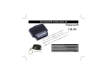
LED strip colour dimmer
Kleurendimmer voor LEDstrips
for use with remote: VM118R
4
7
Graduateur couleur flexibles LED
10
Farbdimmer für LED-module
13
Dimmer color para módulos LED flexibles
16
OPEN
2
3
-
1
4
-
-
COMMON +
5
6
Remote VM118R is not included
Description
-1-2-3-4-5-6-
12V DC input
RED output (3A DC max.)
GREEN output (3A DC max.)
BLUE output (3A DC max.)
Antenna
Colour preview
Beschrijving
-1-2-3-4-5-6-
Descripción
Beschreibung
-1-2-3-4-5-6-
12VDC-Eingang
ROTER Ausgang (3A DC max.)
GRÜNER Ausgang (3A DC max.)
BLAUER Ausgang (3A DC max.)
Antenne
Wiedergabe der Farbe
12 VDC ingang
RODE uitgang (3A DC max.)
Groene uitgang (3A DC max.)
blauwe uitgang (3A DC max.)
Antenne
Kleuraanduiding
-1-2-3-4-5-6-
Entrada 12VCC
Salida ROJA (3A CC máx.)
Salida VERDE (3A CC máx.)
Salida AZUL (3A CC máx.)
Antena
visualización del color
Description
-1-2-3-4-5-6-
Entrée 12 VCC
Sortie ROUGE (3A CC max.)
Sortie VERT (3A CC max.)
Sortie BLEU (3A CC max.)
Antenne
rendu des couleurs
Velleman hereby certifies that the device
VM161 meets the essential requirements
and all other relevant stipulations of
directive ETS 300-220
For the complete conformity declaration
check out :
http://www.velleman.be/downloads/doc/ce_vm161.pdf
Do not mount the unit in the proximity of other electronic devices or metal objects. Straighten the antenna !
Monteer de ontvanger niet in de omgeving van andere electronische toestellen of metalen objecten. Recht de antenne !
N’installer pas l’appareil à proximité d’autres appareils électroniques ou d’objets métalliques. Rajustez l’antenne.
Montieren Sie das Gerät nicht in der Nähe von anderen elektronischen Geräten oder Metallgegenständen. Ziehen Sie die Antenne gerade!
No instale el aparato cerca de otros aparatos electrónicos u objetos metálicos. ¡Enderece la antena!
3
Specifications - features - mounting
Specifications and features
For use with optional VM118R full size remote
Ideal for use with common anode led strips e.g. CHLS4RGB / LDB1-HS3027AC
SPECIFICATIONS
easy remote control operation
Hi power MOSFET outputs
ideal for use with common anode led strips
7 colours
10 dimming steps
FEATURES
LED PWM frequency: ± 300Hz
3x 12V/3A outputs
TX/RX: 433MHz operation
power supply: max. 12V/9A
dimensions: ± 80x70x23mm/3.15x2.75x0.9"
Mounting
WARRANTY
This product is guaranteed against defects in components and construction from the moment it is purchased and for a period of TWO YEAR starting from the date of sale. This guarantee is only
valid if the unit is submitted together with the original purchase invoice. VELLEMAN components Ltd limits its responsibility to the reparation of defects or, as VELLEMAN components Ltd
deems necessary, to the replacement or reparation of defective components. Costs and risks connected to the transport, removal or placement of the product, or any other costs directly or
indirectly connected to the repair, will not be reimbursed by VELLEMAN components Ltd. VELLEMAN components Ltd will not be held responsible for any damages caused by the malfunctioning
of a unit.
4
Operation
VM118R remote control setup
1.
2.
First connect the RGB led-strip to the controller VM161, see page 2.
Place 3 AAA battery's in the remote control
Insert the batteries in the battery
compartment as indicated in figure
and close the compartment.
Remark : Respect your
national and local laws
when disposing of empty
batteries.
LED
1
3
5
7
2
4
6
8
On / Off
Note: All settings remain in memory after battery replacement
3.
First-time configuration of the remote control for use with the VM161 controller
keep button 'on/off' pressed until the led lights
briefly press button ‘1’
briefly press button ’8’ (the led will blink once)
press button 'on/off' twice to confirm the setting (the led will turn off)
5
Operation
4.
Learning the remote to the VM161 controller
make sure that all VM161 controllers that need to respond to the remote are turned on (turn off all others if
necessary)
keep button 'on/off' pressed until the led lights
briefly press button ‘3’ (the led wil blink 3x times)
choose an address between 1 and 8 by pressing the corresponding button briefly
press button 'on/off' twice to confirm the setting (the led will turn off)
Operation
Press button 1 ... 7 to choose the colour.
1 : red
2 : green
3 : blue
4 : yellow
5 : light blue
6 : pink
7 : white
Press and hold button 8 to dim the output.
Dimming direction changes at release.
6
Specificaties – eigenschappen - Montage
Specificaties en eigenschappen
Geschikt voor gebruik met de optionele VM118R afstandsbediening.
Ideaal voor gebruik met ledstrips met gemeenschappelijke anode zoals CHLS4RGB / LDB1-HS3027AC
SPECIFICATIES
gemakkelijk aan te sturen via de afstandsbediening
hi-power MOSFET-uitgangen
ideaal voor gebruik met ledstrips met gemeenschappelijke anode
7 kleurschakeringen
10 dimstanden
EIGENSCHAPPEN
PWM-frequentie van de led: ± 300Hz
3x 12V/3A-uitgangen
zend-/ontvangstfrequentie: 433MHz
voeding: max. 12V/9A
afmetingen: ± 80x70x23mm
Montage
WAARBORG
Dit produkt is gewaarborgd wat betreft gebreken in materialen en vakmanschap op het ogenblik van de aankoop en dit gedurende een periode van TWEE JAAR vanaf de aankoop. De waarborg
geldt enkel indien het produkt voorgelegd wordt samen met het origineel aankoop bewijs. De verplichtingen van VELLEMAN COMPONENTS N.V. beperken zich tot het herstellen van defecten
of, naar vrije keuze van VELLEMAN COMPONENTS N.V., tot het vervangen of herstellen van defecte onderdelen. Kosten en risico’s van transport; het wegnemen en terugplaatsen van het
produkt, evenals om het even welke andere kosten die rechtstreeks of onrechtstreeks verband houden met de herstelling, worden niet door VELLEMAN COMPONENTS N.V. vergoed.
VELLEMAN COMPONENTS N.V. is niet verantwoordelijk voor schade van gelijk welke aard, veroorzaakt door het falen van een product.
7
configuratie van de afstandsbediening
Configuratie van de afstandsbediening
1.
2.
Sluit eerst de RGB ledstrip aan de controller VM161 (zie pagina 2).
Plaats 3 x AAA-batterijen in de afstandsbediening.
LED
Plaats de batterijen in het batterijvak
zoals afgebeeld en sluit het
batterijvak.
Opmerking: Respecteer de
plaatselijke milieuwetgeving
betreffende de verwijdering
van batterijen.
1
3
5
7
Opmerking: De instellingen blijven na de verwijdering van de batterijen in de afstandsbediening bewaard.
3.
Eerst configuratie van de afstandsbediening oor gebruik met de VM161 controller.
Houd de aan-uitknop ingedrukt tot de led oplicht.
Druk kort op knop 1.
Druk kort op knop 8. De led zal kort oplichten.
Druk tweemaal op de aan-uitknop om de instellingen te bevestigen. De led dooft.
8
2
4
6
8
aan / uit
Gebruik
4.
De afstandsbediening in de VM161 controller programmeren
Schakel alle VM161 controllers in die moeten reageren op de afstandsbediening. Schakel alle andere
controllers uit.
Houd de aan-uitknop ingedrukt tot de led oplicht.
Druk kort op knop 3. De led knippert 3 keer.
Kies een adres tussen 1 en 8. Druk daarvoor kort op de overeenkomende knop.
Druk tweemaal op de aan-uitknop om de instellingen te bevestigen. De led dooft.
Gebruik
Selecteer de kleur met knop 1…7.
1: rood
2: groen
3: blauw
4: geel
5: lichtblauw
6: roze
7: wit
Houd knop 8 ingedrukt om de uitgang te dimmen.
De dimrichting verandert van zodra u de knop
loslaat.
9
Spécifications – Caractéristiques – Montage
Spécifications et caractéristiques
Convient pour usage avec la télécommande optionnelle VM118R.
Idéal pour utilisation avec des flexibles à LED à anode commune comme le CHLS4RGB / LDB1-HS3027AC
SPECIFICATIONS
facile à piloter depuis la télécommande
sorties MOSFET de puissance
idéal pour utilisation avec des flexibles à LED à anode commune
7 nuances de couleur
10 réglages de variation
DONNEE TECHNIQUES
fréquence MLI de la LED: ± 300Hz
3 sorties 12V/3A
fréquence de transmission/réception: 433MHz
alimentation: max. 12V/9A
dimensions: ± 80x70x23mm
Montage
GARANTIE
Ce produit est garanti contre les défauts des composantes et de fabrication au moment de l’achat, et ce pour une période de DEUX ANS à partir de la date d’achat. Cette garantie est
uniquement valable si le produit est accompagné de la preuve d’achat originale. Les obligations de VELLEMAN COMPONENTS S.A. . se limitent à la réparation des défauts ou, sur seule
décision de VELLEMAN COMPONENTS S.A. au remplacement ou à la réparation des pièces défectueuses. Les frais et les risques de transport, l’enlèvement et le renvoi du produit, ainsi que
tous autres frais liés directement ou indirectement à la réparation, ne sont pas pris en charge par VELLEMAN COMPONENTS S.A. VELLEMAN COMPONENTS S.A. n’est pas responsable des
dégâts, quels qu’ils soient, provoqués par le mauvais fonctionnement d’un produit.
10
Configuration de la télécommande
Configuration de la télécommande
1.
2.
Connectez d’abord le flexible RGB au contrôleur VM161. Voyez en page 2.
Insérez 3 piles R03 dans la télécommande.
Insérez les piles dans la télécommande comme illustré et refermez le
compartiment des piles.
Remarque : Il convient de
respecter la réglementation
locale relative à la protection
de l’environnement lors de la
mise au rebut de piles usa-
LED
1
3
5
7
gées.
2
4
6
8
On / Off
Remarque : La configuration reste en mémoire après avoir retiré les piles.
3.
Première configuration de la télécommande pour emploi avec le contrôleur VM161.
Maintenez enfoncé le bouton marche/arrêt jusqu’à la LED s’allume.
Enfoncez brièvement le bouton 1.
Enfoncez brièvement le bouton 8. La LED clignote 1 fois.
Enfoncez le bouton marche/arrêt à deux reprises pour confirmer la configuration. La LED s’éteint.
11
Emploi
4.
Programmation de la télécommande dans le contrôleur VM161.
Veillez à ce que tous les contrôleurs VM161 devant réagir à la télécommande soient allumés. Éteignez ceux qui
ne doivent pas réagir.
Maintenez enfoncé le bouton marche/arrêt jusqu’à la LED s’allume.
Enfoncez brièvement le bouton 3. La LED clignote 3 fois.
Sélectionnez une adresse entre 1 et 8 en enfonçant le bouton correspondant.
Enfoncez le bouton marche/arrêt à deux reprises pour confirmer la configuration. La LED s’éteint.
Emploi
Sélectionnez la couleur en enfonçant le bouton 1...7.
1 : rouge
2 : vert
3 : bleu
4 : jaune
5 : bleu clair
6 : rose
7 : blanc
Maintenez enfoncé le bouton 8 pour faire varier la
sortie.
La direction de variation est inversée lors du relâchement du bouton.
12
Technische Daten – Eigenschaften - Montieren
Technische Daten und Eigenschaften
Eignet sich für den Gebrauch mit der VM118R Fernbedienung (Option).
Ideal für die Anwendung mit LED-Streifen mit gemeinsamer Anode wie CHLS4RGB / LDB1-HS3027AC
TECHNISCHE DATEN
einfach über Fernbedienung zu steuern
Hi-Power MOSFET-Ausgänge
ideal ideal für den Gebrauch mit LED-Modulen mit gemeinsamer Anode
7 Farbtöne
10 Dimmereinstellungen
EIGENSCHAFTEN
PWM-Frequenz der LED: ± 300Hz
3x 12V/3A-Ausgänge
Sende-/Empfangsfrequenz: 433MHz
Stromversorgung: max. 12V/9A
Abmessungen: ± 80x70x23mm
Montieren
GARANTIE
Dieses Produkt trägt eine Garantie für fehlerhaftes Material oder Verarbeitungsschäden im Moment des Ankaufs. Sie ist ZWEI JAHRE gültig ab Ankaufsdatum. Die Garantie kann nur
beansprucht werden, wenn das Produtk mit der Originalrechnung abgegeben wird. Die Verpflichtungen der VELLEMAN COMPONENTS AG beschränken sich auf die Aufhebung der Fehler,
oder, nach freier Wahl der VELLEMAN COMPONENTS AG , auf den Austausch oder die Reparation der fehlerhaften Teile. Kosten und Risiken des Transports; das Entfernen und
Wiedereinsetzen des Produkts, sowie alle anderen Kosten die direkt oder indirekt mit der Reparation in Verbindung gebracht werden können, werden durch die VELLEMAN COMPONENTS AG
nicht zurückerstattet. VELLEMAN COMPONENTS AG ist nicht für Schäden gleich welcher Art, entstanden aus der fehlerhaften Funktion des Produkt, haftbar.
13
Die Fernbedienung konfigurieren
Die Fernbedienung konfigurieren
1.
2.
Verbinden Sie zuerst den RGB LED-Streifen mit dem Controller VM161 (siehe Seite 2).
Legen Sie 3 x AAA-Batterien in die Fernbedienung.
LED
Legen Sie die Batterien in das
Batteriefach ein (siehe Abb.) und schließ
Sie das Batteriefach.
Bemerkung: Respektieren Sie
die örtlichen
Umweltvorschriften
hinsichtlich der Entsorgung von
1
3
5
7
Bemerkung: Die Einstellungen bleiben nach Entfernung der Batterien in der Fernbedienung gespeichert.
3.
Erste Konfiguration der Fernbedienung für Anwendung mit dem VM161 Controller.
Halten Sie den EIN/AUS-Schalter gedrückt bis die LED leuchtet.
Drücken Sie kurz Taste 1.
Drücken Sie kurz Taste 8. Die LED leuchtet kurz.
Drücken Sie zwei Mal den EIN/AUS-Schalter, um die Einstellungen zu bestätigen. Die LED erlischt.
14
2
4
6
8
Ein / aus
Anwendung
4.
Die Fernbedienung in VM161 Controller programmieren
Schalten Sie alle VM161 Controller, die auf die Fernbedienung reagieren müssen, ein. Schalten Sie alle
anderen Controller aus.
Halten Sie den EIN/AUS-Schalter gedrückt bis die LED leuchtet.
Drücken Sie kurz Taste 3. Die LED blinkt 3 Mal.
Wählen Sie eine Adresse zwischen 1 und 8. Drücken Sie dafür kurz die entsprechende Taste.
Drücken Sie zwei Mal den EIN/AUS-Schalter, um die Einstellungen zu bestätigen. Die LED erlischt.
Anwendung
Wählen Sie die Farbe mit Taste 1…7 aus.
1: rot
2: grün
3: blau
4: gelb
5: hellblau
6: rosa
7: weiß
Halten Sie Taste 8 gedrückt, um den Ausgang zu
dimmen.
Die Dimmrichtung ändert sich, sobald Sie die Taste
loslassen.
15
Especificaciones – Características – Montaje
Especificaciones y características
Apto para el uso con el mando a distacia opcional VM118R.
Ideal para el uso con módulos LED flexibles con ánodo común como el CHLS4RGB / LDB1-HS3027AC
ESPECIFICACIONES
fácil de manejar con el mando a distancia
acceso directo a 7 ajustes de color
ideal para el uso con módulos LED flexibles con ánodo común
7 matices
10 ajustes del dimmer
CARACTERÍSTICAS
frecuencia PWM del LED: ± 300Hz
3x salida 12V/3A
frecuencia de transmisión/recepción: 433MHz
alimentación: máx. 12V/9A
dimensiones: ± 80x70x23mm
Montaje
GARANTÍA
Este producto está garantizado contra defectos de componentes y construcción a partir de su adquisición y durante un período de TRES AÑO a partir de la fecha de venta. Esta garantía sólo es
válida si la unidad se entrega junto con la factura de compra original. VELLEMAN COMPONENTS Ltd. limita su responsabilidad a la reparación de los defectos o, si VELLEMAN
COMPONENTS Ltd. lo estima necesario, a la sustitución o reparación de los componentes defectuosos. Los gastos y riesgos con respecto al transporte, el desmontaje o la instalación del
dispositivo, o cualquier otro gasto directa o indirectamente vinculado con la reparación, no será reembolsado por VELLEMAN COMPONENTS Ltd. VELLEMAN COMPONENTS Ltd no
responderá de ningún daño causado por el mal funcionamiento de la unidad.
16
Configurar el mando a distancia
Configurar el mando a distancia
1.
2.
Primero, conecte el módulo LED RGB flexible al controlador VM161. Véase página 2.
Introduzca 3 pilas AAA en el mando a distancia.
Introduzca las pilas en el mando a
distancia (véase fig.) y vuelva a cerrar
el compartimiento de pilas.
Nota: Respete las leyes
locales en relación con el
medio ambiente concerniente al tirar las pilas agotadas.
1
3
5
7
LED
2
4
6
8
On / Off
Nota: La configuración se guarda en la memoria después de haber sacado las pilas.
3.
Primera configuración del mando a distancia para uso con el controlador VM161.
Mantenga pulsado el botón ON/OFF hasta que el LED se ilumine.
Pulse brevemente el botón 1.
Pulse brevemente el botón 8. El LED parpadea 1 vez.
Pulse el botón ON/OFF dos veces para confirmar la configuración. El LED se apaga.
17
Uso
4.
Programar el mando a distancia en el controlador VM161.
Active todos los controladores VM161 que deben reaccionar al mando a distancia. Desactive los controladores
que no deben reaccionar.
Mantenga pulsado el botón ON/OFF hasta que el LED se ilumine.
Pulse brevemente el botón 3. El LED parpadea 3 veces.
Seleccione una dirección entre 1 y 8 al pulsar el botón correspondiente.
Pulse el botón ON/OFF dos veces para confirmar la configuración. El LED se apaga.
Uso
Seleccione el color al pulsar el botón 1...7.
1 : rojo
2 : verde
3 : azul
4 : amarillo
5 : azul claro
6 : rosa
7 : blanco
Mantenga pulsado el botón 8 para ajustar la intensidad de luz.
La dirección de ajuste de la intensidad de luz se
invierte al soltar el botón.
18
All repairs should be executed by qualified technicians.
Avoid the installation of the module in locations with standing or running water or excessive humidity. Indoor use only !
Handle the module gently and carefully. Dropping it can damage the circuit board.
Never exceed the protection limit values indicated in the specifications.
As safety requirement vary, please check with your local authorities.
Facilitate the operation of the device by familiarising yourself with its adjustments and indications.
Velleman modules are not suitable for use or as part of life support systems, or systems that might create hazardous situations of kind.
SAFETY INSTRUCTIONS
Reparaties mogen uitsluitend uitgevoerd worden door vakkundige personen.
VEILIGHEIDSAANWIJZINGEN
Installeer de module niet op plaatsen met staand of stromend water of in ruimtes met een te hoge vochtigheidsgraad. Binnengebruik enkel!
Vermijd een ruwe behandeling. Stoten of laten vallen kunnen ernstige schade aanbrengen.
Overschrijdt nooit de opgegeven veiligheidswaarden in de specificaties.
Vermits de veiligheid vereisten verschillen van plaats tot plaats, dient U ervoor te zorgen dat Uw montage voldoet aan de plaatselijke geldende vereisten.
Zorgt ervoor dat u met alle bedieningselementen vertrouwd raakt, wanneer U met het toestel zal werken.
Velleman modules zijn niet geschikt voor gebruik in of als gedeelte van systemen welke levensfuncties in stand houden of systemen welke gevaarlijke situaties van gelijk welke aard kunnen veroorzaken.
CONSIGNES DE SÉCURITÉ
All repairs should be executed by qualified technicians. Toute réparation doit être exécutée par du personnel qualifié.
Évitez l’installation de ce module à proximité d’eau courante ou dormante ou à une endroit avec un taux d’humidité trop élevé.
Evitez les manipulations brutales. Un chute pourrait endommager le boîtier ou les plaque et pourrait causer des défauts.
Ne jamais excéder les valeurs limites de protection indiquées dans les spécifications.
Etant donné que les exigences en matière de sécurité varient d’un lieu à l’autre, vous devez vous assurer que votre montage satisfait aux exigences.
Familiarisez-vous avec tous les réglages et indications de l'appareil afin de faciliter l'opération.
Les modules Velleman ne conviennent pas pour une utilisation dans ou comme parties de systèmes servant à assurer des fonctions de survie ou des systèmes pouvant entraîner des situations
dangereuses, de quelque nature qu‘elles soient.
Lassen Sie Reparaturen durch Fachleute erfolgen
SICHERHEITSHINWEISE
Installieren Sie das Modul nicht in einer Umgebung mit stehendem oder fließendem Wasser oder in einer sehr feuchten Umgebung
Gehen Sie behutsam mit dem Modul um. Es fallen lassen, kann die Leiterplatte und das Gehäuse beschädigen.
Überschreiten Sie nie die in den technischen Daten erwähnten Eingangsgrößen.
Sicherheitsvorschriften können sich ändern, bitte beachten Sie die lokalen Vorschriften Ihres Landes.
Machen Sie sich mit allen Bedienungselement vertraut, wenn Sie mit diesem Gerät arbeiten.
Der von Ihnen gekaufte Bausatz ist aber für den Privatgebrauch konzipiert und nich für den Einsatz in Lebenserhaltenden oder Lebensrettenden Systemen oder unter außergewöhnlichen
Umweltbedingungen (Ex-systeme) geeinet.
El servicio debe ser realizado por personal especializado
LAS MEDIDAS DE SEGURIDAD
No instale el módulo en un lugar con agua estancada o agua corriente, ni en lugares excesivamente húmedos.
Manéjese con cuidado. Dejar caer el dispositivo puede dañar el circuito impreso y la caja.
Nunca exceda los valores límites indicados en las especificaciones.
Las exigencias en materia de seguridad varían de un lugar a otro. Asegúrese que el montaje realizado sea conforme a las exigencias en vigor de su localidad.
Siga cuidadosamente todas las instrucciones y familiarícese con los ajustes al operar este dispositivo.
Los modulo Velleman no son adecuados para una utilización dentro o corno sistema destinado a garantizar funciones para sobrevivir o sistemas conllevando situaciones peligrosas sea cual su naturaleza.
VM161
LED dimmer with RF remote control
USER MANUAL
Belgium [Head office]
Velleman Components
+32(0)9 384 36 11
France
Velleman Electronique
+33(0)3 20 15 86 15
Netherlands
Velleman Components
+31(0)76 514 7563
USA
Velleman Inc.
+1(817)284-7785
Spain
Velleman Components
+32(0)9 384 36 11
Modifications and typographical errors reserved - © Velleman Components nv - HVM161G - 2010- ED2_rev.1
5 410329 419738