1
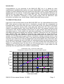
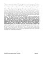
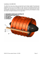
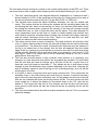
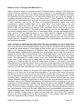
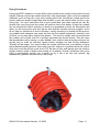
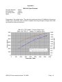
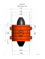
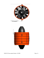
STUMAX AIRCRAFT
27 Wolfe Rd
East Ryde
NSW 2113
Australia
+61 2 8819 4330
www.stumaxaircraft.com
SM110-52 User manual Version 1.0-2008
Page 1
Safety Warning!
Flying R/C aircraft can be dangerous. Use this product at your own risk. If you are not
willing to accept this risk, please return the unit to the vendor. Electric ducted fans may
seem somewhat safer than propellers, however be warned that misuse of this product may
result in serious injury. Always wear eye protection when you are close to a running fan,
hearing protection is also advisable. Never touch any moving part, never throw anything
into the fan when it is running. Always inspect the fan before and after a day's flying for
any damage which may have occurred due to stone chips etc. Please do not continue to
operate this EDF unit if there is visible damage to any part of it. Replacement rotors are
available, please contact your vendor or StumaxAircraft if you require one.
Please Note:
The rotor blades are quite small so some care is required when handling the rotor. Any
carbon fibre filled material will be stiff right up to the point at which it breaks – this is called
brittle failure. The rotor blades are perfectly strong enough for the task they are intended,
however, they will not stand up to inquisitive fingers seeing just how stiff they are. Nor will
they stand up to being gripped whilst undoing/doing up the rotor nut. If, for any reason, you
need to remove the rotor, please hold the rotor by wrapping your thumb and first finger
around the spinner, being careful not to place any load on the rotor blades themselves.
The rotor nut is an M8 so you'll need a 13mm socket. Remember the orientation of the
rotor and replace it in the same orientation.
The rotor and shroud are both polycarbonate based. The rotor is long carbon fibre filled
polycarbonate and the shroud is glass fibre filled polycarbonate. Both materials are perfect
for the job they are doing. Polycarbonate reacts badly to hydrocarbon solvents such as
acetone, lacquer thinners etc as well as CA. Please avoid exposure of these parts to such
solvents.
SM110-52 User manual Version 1.0-2008
Page 2
Introduction
Congratulations on your purchase of the SM110-52 EDF unit. It is, based on other
manufacturer's published test results, the most efficient EDF unit available. It also has a
number of unique features which set it apart from other EDF units. These features will be
detailed later in this manual. Combine the unique features and unbeatable efficiency, the
SM110-52 is the class leader in the 3-4kW EDF field. This manual will provide the user
with all the information necessary to enjoy great success with his SM110-52, with
information on battery care, model design, system setup and flying covered.
The SM110-52 Described
Let's have a look at what makes up the SM110-52 EDF unit. It's a little different from most
EDF units around so take some time to familiarise yourself with the components as
illustrated below. You'll notice that the rotor is at the rear of the unit (called an inlet guide
vane/rotor or IGV/rotor layout) unlike most other fans which have the rotor at the front
(called a rotor/stator layout). Why is the SM110-52 like this? Two reasons: efficiency and
convenience. Ask 100 fan designers which layout is more efficient and most will say the
rotor/stator layout is. That's correct, but with some qualification. For ultimate efficiency, the
rotor/stator layout will be slightly more efficient. However, that will be at a very low power
level. Modern EDF units operate at extremely high power levels for their size, this is
referred to as a high work coefficient. At the high work coefficients that modern EDF units
operate, the IGV/rotor layout is more efficient, yet harder to design correctly (which is why
we don't see many IGV/rotor EDF units). If you were to plot a graph of thrust vs power, for
most fans you would see an almost straight line for the lower power side of the scale, then
as the power increases the curve will flatten off, indicating that we are getting less and less
thrust for every extra Watt of power we put in. The rate at which the curve flattens off is
greater for a rotor/stator layout fan than for an IGV/rotor layout fan. For a 110mm fan, this
“flattening off” of the thrust curve begins at around 3kW, which is right where we are
operating. See the graph below for a better understanding.
110mm EDF unit - Thrust vs Power input
Comparison between IGV/rotor and rotor/stator layouts
7000
6000
Thrust - grams
5000
4000
3000
2000
IGV/rotor
Rotor/stator
1000
0
0
500
1000
1500
2000
2500
Power Input - Watts
SM110-52 User manual Version 1.0-2008
3000
3500
4000
Page 3
The second reason for using an IGV/rotor layout fan is one of convenience. This layout
allows the motor to face forward, shortening the motor wires considerably. No longer do
the motor wires need to undergo a 180 degree bend just to get in front of the fan to
connect to the esc. Some manufacturers place the esc in the fairing behind the motor to
avoid this problem, however all they do is create the need for longer battery leads. Long
wires and high voltages lead to very high voltage spikes which can destroy an esc in
seconds. A rotor/stator layout fan will require the battery be kept very close to the fan to
keep battery leads short enough for the esc to survive, with the requirement that you have
to use their special batteries which saddle the fan unit in order to keep battery leads short.
IGV/rotor fans don't have this problem. The motor wires face forward, which allows the fan
to be placed further aft in the aircraft so that the battery may be placed on or close to the
CG. The benefits of this are twofold: the longer inlet ducting will work better, and it allows
you to try different capacity batteries without affecting the CG.
Looking at the SM110-52 you'll notice the IGV stage is cast and machined from
aluminium. This serves two functions: it provides a massive amount of heatsinking for the
motor, as well as being mechanically very rigid and strong to support the motor and rotor
within the shroud. The motor is a precision fit inside the IGV tube for maximum thermal
efficiency. The carbon fibre nosecone smooths the air entering the IGV stage and provides
an aerodynamic fairing for the motor wires. At the tip of the nosecone there is a small hole
to allow some air to pass in for additional motor cooling (this hole is not necessary if
operating below 3kW). This air passes through the motor and exits in the small gap
between the motor and the rotor. The rotor is injection moulded from carbon fibre filled
polycarbonate. This material is very rigid, almost as rigid as hand laid carbon fibre. The
rotor has 12 blades which is one of the reasons the SM110-52 has such a unique sound.
The spinner is hand laid carbon fibre, made using a male and female mould, which
ensures a uniform wall thickness. The shroud is injection moulded from glass fibre filled
polycarbonate. This material is very stiff and tough, and should survive any unfortunate
encounters your aircraft has with terra firma.
SM110-52 User manual Version 1.0-2008
Page 4
SM110-52 User manual Version 1.0-2008
Page 5
Installation of the SM110-52.
The SM110-52 comes with rubber grommets with crush bushes installed. This allows soft
mounting of the unit to the mounting rails. Use 3mm or 4-40 machine screws with flat
washers to fix the unit in your aircraft. In order to provide a hard surface for the crush
bushes, glue flat washers to the mounting rails. This way, the rubber grommets will be
sandwiched by the flat washers, with the crush bushes providing crush resistance to allow
the screws to be tightened properly. See image below.
SM110-52 User manual Version 1.0-2008
Page 6
Inlet and Exhaust Ducting
In order to function properly, ducted fans need to be fed smooth, turbulence free air. Most
kits will provide some sort of inlet ducting, however if you are scratch building you need to
provide ducting to direct air from outside the model to the fan. This ducting needs to
connect to the front of the fan and be flush with the inside surface. This means you will
need to provide a step in the end of the duct so that it wraps around the outside of the front
of the shroud, yet is flush with the inside surface. See image below. A simple lip can be
created by wrapping some 2mm balsa, 12mm wide around the outside of the inlet duct,
then wrapping some 20mm wide 0.4mm ply around that so that the extra ply is effectively
wrapping around the front of the fan shroud. Simply wrapping the duct around the outside
of the shroud will work, however there will be a small loss due to turbulence created by the
edge of the shroud. It is important to seal the inlet ducting at the fan connection. This is to
allow build up of dynamic pressure in flight, which will improve performance. Similarly, the
exhaust needs to be ducted out of the model. This is simpler than the inlets, and less
critical. The exhaust tube may be simply wrapped out of mylar or similar plastic sheet,
fixed to the shroud by wrapping it around the rear edge and fastening with tape. The small
step created here doesn't seem to affect the performance at all. The exhaust duct also
needs to be sealed to prevent pressure loss occurring.
SM110-52 User manual Version 1.0-2008
Page 7
The inlet and exhaust ducting are critical to the overall performance of the EDF unit. There
are some simple rules to apply when designing inlet and exhaust ducting for your model:
1. The inlet “catchment area” (see diagram below for explanation of “catchment area”)
should ideally be 100% of the swept area of the fan unit. Swept area is the area of
the shroud minus the area of the hub. For the SM110-52 it is 7380 mm².
2. The exhaust area should be about 86-90mm diameter, but can be outside this
range. This means that the air leaving the exhaust will be traveling faster than the
air entering the inlet, which is how we get our thrust. You will lose a little static thrust
by closing the exhaust down, however the velocity of the flow will increase enough
to offset this loss, so that in flight the thrust will be higher. This ratio depends on
many parameters such as the style of model (ie faster models may benefit from
even smaller exhausts, whereas slower models may do better with larger exhausts)
and the actual catchment area of the inlet. There is no hard and fast rule, best
results are achieved with some experimentation.
3. The inlets need to have a nicely rounded lip. The ideal profile for the inlet lip is half
of a 2:1 ellipse. Most models for a fan this size will do best with an inlet lip thickness
of at least 6mm. The faster the model, the smaller this thickness may be, however if
the lip is too sharp there is the danger that the flow will separate from the inside
edge of the lip, causing very turbulent air to enter the duct with the result that thrust
will be severely affected. On aircraft which had a very sharp lip, such as the F-100
and Mig-21, there is no choice but to use a reasonably sharp lip, but try to avoid
going thinner than say 3mm.
4. The inlet duct should remain a fairly constant cross section or if necessary, any
changes in cross sectional area should be as gradual as possible. It's most likely
that the inlet duct will need to diverge up to the face of the fan. A good rule is to
keep the cone half angle at less than 5°. This allows the air to slow down slowly
enough so that the boundary layer remains attached to the duct wall. Allowing the
duct to suddenly expand is one of the big no-no's of ducting design, as it will act like
a blockage in the duct.
5. It is better to have a long inlet duct and a short exhaust duct. This is because the
boundary layer in the inlet ducting will most likely be laminar. A laminar boundary
layer has much less drag than a turbulent one, so the greater the amount of laminar
flow we can maintain the lower the ducting losses will be. This also works well with
most models as it allows the battery to be placed close to the CG, with the fan
behind it. The longer the inlet duct is, the chances are that the duct will also have
more gentle curves which will also be of benefit as the air meeting the fan will be
smoother
6. The inlet and exhaust ducts should be sealed around the shroud. This is to prevent
pressure leakage.
SM110-52 User manual Version 1.0-2008
Page 8
SM110-52 User manual Version 1.0-2008
Page 9
Battery Choice, Charging and Maintenance.
Battery choice is always a contentious issue. Customer loyalty is strong in this field, with
many customers swearing by a single brand, unwilling to try anything else. Whatever
brand is your favourite, you must ensure that the battery chosen is suitable for the task.
The SM110-52 will draw 80-90A on 11S lipo. This means your cells must be capable of
supplying 80-90A continuous. Using cells which have a “burst” capability of 80-90A is
asking for very short battery life, and given the cost of an 11S pack this size, this makes for
a very expensive way to fly. Be wary of manufacturer's claims about their cell's
performance, always de-rate them by at least 20%. This means that if the cell
manufacturer claims that their cells are capable of 25C continuous, take 80% of that,
which is 20C, and use that as a maximum. Also, remember that for long cell life you can
only use 80% of the capacity of the pack at the discharge rate you are operating at. Lipo
cell have a capacity which is rated for a 1C discharge. When you start discharging at high
rates, such as 15C the capacity drops, so your actual capacity is based on the capacity
available at your discharge rate, and then you should only use 80% of that capacity.
Remember that cell manufacturers will hype their product and get away with it as not many
people have the capability or technical knowledge to test their product in accordance with
the correct test methods.
When selecting a battery always think about how long you want to fly on a given pack.
Sure, you can get cells which will deliver 30C constant discharge, but do you really only
want 2 minutes of full throttle flight? Models large enough for the SM110-52 should be able
to handle the extra weight of a pack large enough to give you 3-4 minutes of full throttle
flight. A 16C discharge equates to 3.75minutes. With an 80A current draw, 16C means
5000mAh usable capacity will be required. You will probably use at least 30 seconds for
takeoff, so there's only 3.25minutes left. With careful flight tactics you should be able to
achieve 6-8 minute flights using a pack this size. Efficient flying is the key, don't waste
power. The Neumotors 19 series motors used in the SM110-52 throttle very efficiently,
unlike most 2 pole motors which rapidly heat up when operated at part throttle. When
pulling out of loops or split S's bring the throttle back to about ¼ and apply it smoothly
when pulling out to maintain speed. If you've just done a fast pass there's no need to keep
it fast when it's past your viewpoint – you can't really see how fast it's going as it flies away
anyway. All these little tricks add up to quite a saving in energy which means longer flights.
For long battery life, always let the pack cool down before recharging it. A good rule of
thumb is to let them cool to around body temperature. The cells in the centre of the pack
will always be warmer than the cells on the outside, so take this into account. Cell voltage
is very dependent on temperature, so having all the cells at the same temperature is very
important when recharging as it helps ensure that the individual cells all have the same
voltage. Balance charging is a good way to keep your pack in good shape, however, if the
individual cells are at different temperatures the balancer will be struggling to get it all
balanced out. Some brands of modern lipos claim to be able to be charged at higher rates
than what we are used to for lipos. The cell manufacturers rarely provide any information
as the to effect of faster recharging with regards to cell life. Don't forget that they want to
sell more batteries. At the end of a day's flying don't leave your batteries lying around in a
highly discharged state, bring them up to about 50% capacity. Some chargers have what is
called a “storage” charge mode for lipos, this will bring them up to about 50% capacity,
which is the level recognised to be best for longevity. If your charger can't do it for you,
then fully charge them then perform a timed discharge.
SM110-52 User manual Version 1.0-2008
Page 10
Flying Techniques
Flying large EDF models is no more difficult than a prop driven model of the same size and
weight, however ducted fan models have their own peculiarities which must be respected
otherwise you'll end up with a very sorry looking pile of bits. Ducted fan models tend to be
heavier and have smaller wings than most models, so you will need to allow for this in your
flying style. You can't treat them like a sport model and yank them around the sky. Be
smooth with your flying and the model will perform that much better. Ducted fan models
rely on airspeed for control authority, as there is no propwash over the tail. Remember this
when you are flying slow, and don't get so slow that the controls become sluggish, as it's
all too easy to overcontrol in such a situation, usually resulting in a tipstall into the ground.
Any sudden pitch changes may upset the flow into the intakes temporarily, causing a loss
of thrust, so no snap pylon racing turns please. The thrust to weight ratio of most ducted
fan models will be lower than for a similarly powered prop driven aircraft. This will mean
that acceleration will be slower, so plan ahead if you need to abort a landing and give the
aircraft time to build up sufficient speed before climbing out and turning downwind.
Takeoffs will be longer, you need to allow the model sufficient time to accelerate to flying
speed before breaking ground. Some jets have their intakes in a position which will tend to
suck them onto the ground, such as an F18. Be wary of this, and always give the model a
slightly positive angle of attack when sitting on its wheels. Overall, remember that you're
flying a performance aircraft, not a trainer, so fly it like a jet, fast and smooth, big
manoeuvres, graceful rolls and lots of fast fly-bys.
SM110-52 User manual Version 1.0-2008
Page 11
Appendix I
SM110-52 Specifications:
Nominal diameter:
Hub Diameter:
Fan Swept Area:
Mass:
110mm
52mm
7380mm²
700g.
Performance: See graph below. This test was performed using 11S 4900mAh Neuenergy
25/50C lipos. Later cells, such as 30/60C capable cells will give higher voltage under load,
and therefore higher performance.
SM110-52 User manual Version 1.0-2008
Page 12
Appendix II
SM110-52 Dimensions
SM110-52 User manual Version 1.0-2008
Page 13
SM110-52 User manual Version 1.0-2008
Page 14
Copyright 2008 StumaxAircraft. This manual may not be reproduced wholly or in part
without the written permission of StumaxAircraft.
SM110-52 User manual Version 1.0-2008
Page 15