1
CPU JUMPER TABLE
CPU*
Version
Ga me
LaserWars
Secret Service
Torpedo Ailey
Time Machine
Playboy
Vert
Ver2
Ver2
Ver2
Ver2
• Ver 2
ROM
Location
sc
sc
SB,SC
58,5C
58,5C
58,5C
Jumpers
lnstalled
Removed
J1b,J3,J4,J6a,J7a,&J8
J1 b,J3,J4,J5a,J6a,J7b,&J8
J1 b,J3,J4,J5b,J6b,J7b,&J8
J1 b,J3,J4,J5b,J6b,J7b,&J8
J1b,J3,J4,J5b,J6b,J7b,&J8
J1b,J3,J4,J5b,J6b,J7b,&J8
J1 a,J2,J5,J6,&J7b
J1a,J2,J5,J5b,J6b,&J7a
Jt a,J2,J5,J5a,J6a,&J7a
J1 a,J2,J5,J5a,J6a,&J7a
J1 a,J2,J5,J5a,J6a,&J7a
J1 a,J2,JS,J5a,J6a,&J7a
*Version 1 has a 2K RAM whlch ls a 24-pln IC at location 50.
*Version 2 has an BK RAM which is a 28-pln IC at location 50.
Power-up CPU Self Tests
Upon power-up, the CPU board performs a series of self tests of major components. Turn the game on while
observlng the LEDS on the CPU board. Tests of the PIAs, RAM, and EPROMs are performed automatlcally and
results of the test are lndicated by the PIA LED.
Wlth ali tests passed, the LEOs lllumlnate ln the followlng sequence at power turn-on. The PIA and + SV LEOs
llluminate immediately. Approximately 1/2-second later the PIA LED goes out and the Blanking LED llluminates;
the + SV and Blanklng LEDs remaln llluminated untll the game is turned off. Test fallures are lndlcated with the PIA
LED:
PIA LED
SUSPECT COMPONENT
Stays On
Flashes 1 Tlme
Flashes 2 Times
Flashes 3 Times
One of the 6821 PIAs
6064 RAM at location os.
EPROM at location 85.
EPROM at location cs.
QUICK REFERENCE FUSE CHART
PPB BOARD
POWER SUPPLY BOARD
Ft SA Slo-Bio G.I. 6.3VAC
F2 SA Slo-Bio G.I. 6.3VAC
F3 SA Slo-Bio G.I. 6.3VAC
F4 SA Slo-Bio G.I. 6.3VAC
F5 SA Slo-Bio Flipper Power 48VAC
F6 3A Slo-Bio PPB Solenoids/Fiash Lamps (34VDC}
F1 7A Slo-Bio + SVDC Regulator Input (9VAC)
F2 7A Slo-Bio + SVDC Regulator Input {9VAC}
F3 0.25A Slo-Bio Dlsplay Reg. Input (90VAC)
F4 8A Slo-Bio Swltched Illumination Buss (18VDC)
F5 4A Slo-Bio Solenoid Buss (34VDC)
F6 SA Slo-Bio Solenoid Buss {34VDC)
PLAVBOV
TABLE OF CONTENTS
GAME SPECIFICATIONS .................................................................................................... 1
Power Requlrements ................................................................................................................................... 1
Major Assembly and Fuse Locations........................................................................................................... 1
Circuit Board PROM Locations .................................................................................................................... 1
Transportation .............................................................................................................................................. 1
ASSEMBLY PROCEDURES ................................................................................................ 1
GAME OPERATION ............................................................................................................ 3
Standard Features ........................................................................................................................................ 3
Automatlc Bali Tlme Averaglng .................................................................................................................... 3
Manual Percentaging ...................................................................................................................................4
Game Specifie Features ........................................................:...................................................................... 4
AUDIT FUNCTIONS .............................................................................................................. 5
General ..........................................................................................................................................................5
'Qulck Look' Functlons .................................................................................................................................5
Expanded Functlons .....................................................................................................................................7
Game Specifie Funetlons ............................................................................................................................. 7
GAME ADJUSTMENTS ...................................................................................................... 9
General .......................................................................................................................................................... 9
Replay and Generic Features........................................................................................................................9
Slngle-Function Difflculty Adjustments ...................................................................................................... 11
Novelty/5-Baii/Add-A-Ball Rules ................................................................................................................. 11
Ga me Priclng .............................................................................................................................................. 12
Addltional Generic Features........................................................................................................................ 14
Ga me Specifie Features ............................................................................................................................. 16
DIAGNOSTIC PROCEDURES ........................................................................................... 19
Entering Diagnostics .................................................................................................................................. 19
Sound Tests ................................................................................................................................................ 19
Digital Display Tests .................................................................................................................................... 21
Switch Tests .................................................................................................................................................22
Lamp Tests .................................................................................................................................................. 24
Coll/Flash Lamp Tests .................................................................................................................,......
26
Return to Game Over .................................................................................................................................. 26
v .......
SERVICING DIAGRAMS .................................................................................................... 28
Power Wirlng Diagram ...............................................................................................................................28
Cabinet Wlrlng Diagram ............................................................................................................................. 29
Comblned Display Connections ................................................................................................................ 30
Backbox Wlrlng Diagram ............................................................................................................................ 31
Playfleld Coll/Rash Lamp Wlrlng Dlagram ................................................................................................. 32
Playfleld Special Coll and Flipper Wiring Diagram .................................................................................... 33
Playfield Switch Wiring Diagram ................................................................................................................ 34
Playfleld Lamp Wlrlng Dlagram .................................................................................................................. 35
CPU Board .................................................................................................................................................. 36
Power Supply Board ..................................................................................................................................41
Digital Stereo Sound Board ....................................................................................................................... 42
Display Board ............................................................................................................................................. 44
PPB Board ..................................................................................................................................................46
PARTS IDENTIFICATION ................................................................................................... 47
Playfleld Top Parts ....................................................................................................................................... 47
Playfleld Rubbers ........................................................................................................................................ 48
Baekbox Parts ............................................................................................................................................. 48
Playfield Bottom Parts ................................................................................................................................. 49
Cabinet Parts ...............................................................................................................................................50
UNIQUE PARTS ................................................................................................................... 51
© Copyright Data East Pinball,lnc. 1989
ii
DATA EAST LIMITED WARRANTY
Data East USA, lnc., C'Seller'1} warrants only to the Initial purchaser of lts products that the Items llsted below are
free from defects ln materlaJ and workmanshlp under normal use and service for the warranty perlod speclfled:
PRINTED CIRCUIT BOARDS (GAME LOGIC) 60 DAYS
No ether parts of Seller's product are warranted.
Warranty periods are effective from the Initial date of shlpment from Seller to lts authorlzed dlstrlbutors.
Seller's sole llablllty shall be, at lts option, to repalr or replace products whlch are retumed to Seller durlng the
warranty perlods speclfled, provlded:
1. Seller is notlfied promptly upon dlscovery by purchaser that stated products are defective.
2. Such products are property packaged and then retumed frelght prepald, to Seller's plant.
This warranty does not apply to any parts damaged durlng shlpment and/or due to lmproper handllng, or due to
improper installation or usage, or alteration. ln no event shaJI the Seller be Hable for any anticlpated profits, Joss
of profits, Joss of use, accidentai or consequentiaJ damages or any ether tosses lncurred by the customer ln
connectlon with the purchase of a Data East USA, product.
WARRANTY DISCLAIMER
EXCEPT AS SPECIFICALLY PROVIDED IN A WRITIEN CONTRACT BETWEEN SELLER AND PURCHASER,
THERE ARE NO OTHER WARRANTIES, EXPRESS OR IMPLIED, INCLUDING ANY IMPUED WARRANTIES OF
MERCHANTABILITY OR FITNESS FOR A PARTICULAR PURPOSE.
.
WARNING-This equlpment generales, uses, and can radiale radio frequency energy, and If not lnstalled and used
ln accordance wlth the Instructions manual, may cause Interference to radio communications. lt has been tested
and found to comply with the llmlts for a Class A computing deviee pursuant to Subpart J of Part 15 of FCC Rules,
whlch are deslgned to provlde reasonable protection agalnst such Interference when operated ln a commercial
envlronment. Operation of this equlpment ln a resk:lentlal area ls llkely to cause Interference ln whlch case the
user at his own expanse will be requlred to take whatever measures may be requlred to correct the Interference.
iii
GAME SPECIFICATIONS
POWER REQUIREMENTS
This game is provlded with a 3-prong plug and must be connected to a properly grounded outlet to reduce
shock hazard and Insu re proper ga me operation. Refer to AC Power Wiring Dlagram for transformer connections
requlred for normal, hlgh, and low fine conditions.
Normal Une: 109 to 129 Vac (211 to 225 Vac)
Hlgh Une: (226 to 235 Vac)
Low Une: 95 to 108 Vac (200 to 210 Vac)
MAJOR ASSEMBLY AND FUSE LOCATIONS
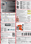
Aefer to the Ga me Illustration (page 2) to identify locations of the major assernblles, and fuse values and locations.
PROM SUMMARY
CPU Board: Location SB, SC
Sound Board: Locations 6F (Volee ROM 1), 4F (Volee ROM 2), and 7F (Sound ROM)
TRANSPORTATION
To reduce the posslbllity of damage, observe the following precautions whenever transportlng the game. Lower
the backbox and secure it to the cabinet. Aemove the legs and secure the gama wlthln the transportlng vehlcle.
GAME ASSEMBLY PROCEDURES
(Refer to the Game Illustration on page 2)
1. Open the top of the carton and lay it on lts side with the bottom of the cabinet down. Uslng the plastic baoding
strip as a handle, slide the game out of the carton.
2. Aemove ali packing materlal. Locate cabinet legs ln fUler packlng lnserts and assembly parts package ln the
cashbox. There should be four leg levelers, elght leg bolts, two head bolts with washers, and three.plnballs.
3. Attach leg leveler from the parts package to each leg, make sure that each Javeler ls threaded through a hex
nut before threading it lnto the leg.
4. Support rear of cabinet and attach rear legs uslng two leg bolts for each leg.
5. Support front of cabinet and attach front legs uslng two leg bolts for each leg.
6. White assuring that no cables are belng plnched, carefully ralse the backbox and temporarily secure lt ln 1ts
upright position with the clamps provlded on the rear of the cabinet.
WARNING
Do not attempt to move the game with the backbox secured ln this temporary manner. If moved, the backbox
could come unclamped and suddenly fall to the lowered position resultlng in possible lnjury to personnel and
equlpment damage.
1
Backbo)( Layaut
Ill
lll·-~·
~"'-~,....;-...,c;;
•
Co l b
FIOsh Lamps
t/-12
voc
•5VOC
,,. .....
GAME ILLUSTRATION
7. Remove the backbox keys from the clip on the lnslde of the coin door and unlock and carefully remove the
backglass. Set the backglass aslde.
8. Carefully remove the playfleld glass and set lt aslde.
9. Obtaln the two bolts and washers from the parts package and open the backbox lnsert board. Secure the
backbox to the cabinet pedestal with the two bolts and washers.
10. Check ali connectors ln the backbox for loose wlre termlnatlons. Reseat any loose wlre by pushing ln on the
terminal.
11. Push on ali connectors plugged lnto the CPU board, Sound Board, Power Supply Boards, and (on lnsert board)
Olsplay board to check that they are proper1y seated.
12. Check that the fuses on the Power Supply board, PPB board and fuse panel are seated properly.
13. Ralse the playfleld and the support bar on the rlght slde of the cabinet; support the playfleld by lnsertlng the
support bar lnto the countersunk notch on the bottom slde.
14. Check ali cabinet cable and playfleld lamp board connecter termlnatlons.
2
t 5. Remove the Plumb tUt from the parts package and lnstall on the panel on the lnslde left of the cabinet. Note
that this game ls not equlpped wlth a bali roll tUt.
16. Lower the playfleld and level the playfleld slde-tcrsk:le by adjustlng leg levalers.
17. The playfleld front-to-back Incline ls factory set at approxlmately 6 degrees.If a pltch lndlcatlng meter ls not
avallable, adjust the front and rear levelers to the lowest position for the proper pitch. Readjust slde-to-slde levet
as requlred.
NOTE
The playfleld Incline affects dtfflculty of play. Use the recommended Incline; game dlfflculty Js best varled uslng
game adjustments.
18. Check the plumb tilt and adjust as requlred.
19. If deslred, perform any self tests at this tlme. With the lnsert door closed, carefully relnstall and lock the backglass.
..
20. Place the three plnballs on the playfield near the outhole and carefully relnstall the playfleld glass.
21. If deslred, make game prlclng and Add-A-Bali, Novelty, or 5-Ball Play adjustments at this tlme.
GAME OPERATION
STANDARD FEATURES
lnsert coln(s). the game ''Wolf whlstles"1 for the flrst credit and plays the Playboy Theme for each subsequent coin
and the Player 4 dlsplay lndlcates the number of credits posted. Depress the credit button and a start-up sound ls
produced( the posted credits are reduced by one, Player 1 dlsplay flashes. Player 4 dlsplay lndlcates BALL1 , and
a bali is served to the plunger trough. Addltlonal players may be added by depresslng the Credit button before the
end of h"ll1.
The second closure {adjustable) of the plumb bob tilt switch tilts the ballin play. Closure of the siam tilt switch ln
the coin door ends the current game{s).
At the end of each bali, earned bonuses are collected. At the end of the last bali for the last player and after bonuses
are collected, the system produces a random 2-dlgit number {a multiple of 10; 00 to 90) for a Match feature
(ad]u5table). Matching the last two digits of a player score wlth this number awards a credit. Players exceedlng
high score levels receiVe free credits (ad]ustable) and are able to enter thelr Initiais wlth the new Hlgh Score
achieved. The gama then proceeds into the game-over mode and then to the anract mode. A custom message
(adjustable) can be dlsplayed during the anract mode.
AUTOMATIC BALL TIME AVERAGING
c
A bali tlme averager feature ls provided which can make automatlc adjustments affectlng player appeal.Thls feature
is provided by 'qulck look' adjustment Ad 15 and ls enabled as the factory settlng. Perlodlcally a check ls made of
the average bali time and adjustments are made to maintain approximately 65-second bali tlme. This check ls
made at the same lime that hlghest scores are reset {expanded ADJUSTMENT E Ad 36) so make sure that E Ad
36 is not set to OFF. (Note that the other highest score adjustments may be dlsabled If deslred.) Refer to Game
Adjustments for additJonal details.
3
MANUAL PERCENTAGING
This gama ls equlpped wlth Manual Percentage Adjustment.
As prevlously wlth our games, you can either set operator adjustments for a replay percent or you can set a flxed
replay score.
• •
If you set operator adjustments for a partlcular replay percent, the gama will compute a recommended score to
keep the game at that replay percentage.lf a change Js recommended and the gama coin door ls opened, the
dlsplays will lndlcate a recommended replay score to beat and knock the Knocker to alert the operator. By pressing
the start butten, the score to beat wUI be changed to the recommended level. If you close the coin door or go lnto
audit or adjustment mode, no score change will be made.
You may choose to Ignore the recommended change; for example, you may not think fast week's players were
the usual crowd . Just close the door and the message will dlsapear wlthout alterlng the existing levet. Or you may
choose to make a different score to beat adjustment; this ls dona by utllizlng adjustment AD02.
GAME SPECIFIC FEATURES
Top La ne• Completlng H-M-H steps up the Bonus Multiplier to 2X,3x,4x,& 5x .Upon the 5th complet ion the Splnner
Extra Balllamp llghts.Every completion of the the Top Lanes spots a latter on the PLAYBOY Targets.
PLAYBOY- Spell P-l-A-Y-B-0-Y by hlttlng each of the targets and receive the flashlng award dlsplayed ln the pool
patio.
PINBALL- Extra Baii·Every ramp shot made durlng Multi-ballllghts a letter ln P-1-N-B-A-l-l on the speaker panel.
Completlng PINBAll llghts the Spinner Extra Bali Lamp.
Bunny Hop- Shoot the left and right ramps to re-light the Bunny Hop Klcker (Laser Kick) .
Mansion Million Countdown-Any ramp shot spots a letter ln the word MANSION shown on the dlsplays and back
panei.Spelllng the word MANSION lnltiates the Million countdown tlmer.As the tlmer tlcks away the Mansion bonus
points dlmlnlsh quickly. the faster you make another ramp shot the hlgher the bonus you collect.
Photo Shoot Speclai-Each time the drop targets are completed the center Photo Shoot feature increments by
one.After five "Photo Shoots" the Special Lamp llghts.When the Drop Targets are completed again the Speclalls
awarded.
Mansion Zoo- Complete the animal targets ln the mansion zoo to start a countdown tlmer. Du ring countdown the
points awarded by ali playfleld swltches will Double,Triple, Quadruple etc. dependlng how many times the animal
targets were completed.
Mufti-Bali & Super Ramp Jackpots--lock 2 Balls ln the Grotte to enable the multlball feature.Shooting elther ramp
shot releases the locked baUs.WhUe ln Multlball any ramp shot will award the Jackpot.
Refer to the Gama Specifie Adjustments on page1B for addltional Information.
4
AUDIT FUNCTIONS
GENERAL
There are 69 audit functlons provlded for accountlng purposes and for evaluation of game dlfflculty adjustments.
Audit functlons are split into two groups. There are el even most-usecl audits {AU01 through AU11) ln a 'quick look'
group and 571ess-usecl audits (E AU13 through E AU69), ln an 'expandecl' group. The varlous auditing functions
are summarizecl in the AU DITI NG FEATU RES TABLE and, wh en accessed, are shown on the player score displays.
The Audit Number is shown in the Player 3 Dlsplay, the Description in the Player 1 and 2 Displays, and the Audit
Total ln the Player 4 Display. Access and controlls provlded from swltches located on the inside of the coin door.
To access audit functlons,open the coin door and make sure that the FORWARD/REVERSE swltch is ln the
FORWARD (up} position. Oepress the STEP swltch and the game name ls shown ln the Player 1 and 2 dlspiays,
the Player 3 display is blank, and the PROM revision levet ls shown ln the Player 4 dlsplay. This indicates access
to audit functions.
..
With the FORWARD/REVERSE push-button switch still in the FORWARD (up) position, depresslng the STEP
push-button switch advances through the audit functlons one at a tlme. To review lower-numbered tunctlons, set
the forward/reverse push-button switch to the REVERSE (down) position and operate the STEP push-button switch.
To access expanded audits, operate the step push-button untll AU12, EXPAND AUDITS is dlsplayed. Set the cholce
to ON as lndlcated ln the Player 4 dlsplay by depresslng the Game Start push-button and then depress the step
push-button. The request ls lnstalled andE AU131s dlsplayed. When you exit audits and adjustments, the AU12
setting ls returned to off for the next tlme that a revlew of audits are requlred.
Audit totals may be reset to zero using Game Adjustment Ad17, Audits Reset. Game adjustments (Ad01 to Ad19
and E Ad20 to E Ad59) begin after the last audit function (AU12 or E AU69 ). Once audits functions have been
recorded, and If no adju~tments are required, you may return the game to the attract mode. If adjustments are
required, continue pressing the STEP button untll the game adjustments are reached. See Game Adjustments for
details.
'QUICK LOOK' FUNCTIONS
Total Paid Credits (AU01)- the total number of paid credits ls displayed.
Free Percent (AU02) ls Free Total (E AU14) dlvided by Plays Total (E AU13).
Bali Time Average (in seconds) (AU03) ls Total Play Time (in minutes) (E AU20) dlvlded by Total Balls Played (E
AU21) wlth the result multlplied by 60.
Coins (AU04, 05, and 06) - These three audit totals are provided to show the amount of coins reglstered for the
left, right, and center coin chutes, respectively.
Replay Percentage (AU07) is the Replay Total awards for exceeding replay score levels (E AU15) dlvided by Plays
Total (E AU13).
High Score Percentage (AU08) ls High Score Total (E AU19) divided by Plays Total (E AU13).
:.
Extra Bali Total (AU09) is the total number of extra balls awarded.
Extra Bali Percentage (AU10) ls AU09 dlvlded by Balls Total (E AU21).
Cycles Burn ln (AU11) provldes the number of diagnostic burn-in cycles (factory use).
Expand Audits (AU12) permits viewing of expanded audits.
5
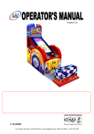
Playboy
Audit Table
6
Audit Number
(Piayer 3 Display)
AU01
AU02
AU03
AU04
AU05
AU06
AU07
AU08
AU09
AU10
AU 11
AU 12
EAU 13
EAU 14
EAU 15
EAU 16
EAU 17
EAU 18
EAU Hl
EAU20
EAU21
EAU22
EAU23
EAU24
EAU25
EAU26
EAU27
EAU28
EAU29
EAU30
EAU31
EAU32
EAU33
EAU34
EAU35
E AU36
EAU37
EAU36
EAU3Q
E AU40
EAU41
EAU42
EAU43
E AU44
EAU 45
EAU46
EAU47
E AU48
EAU49
EAU 50
EAU 51
EAU 52
EAU 53
EAU 54
EAU 55
EAU 56
EAU 57
EAU 58
EAU 59
EAU60
EAU61
EAU 62
EAU63
E AU64
E AU65
EAU66
E AU67
EAU66
EAU6Q
Audit DeectlpUon
(Piayers 1 & 2 Displays;
4.ïl'f:
Playboy PROM ID
Total Pald Credits
Free Peroent
Bali Tlme Average
Coins Left
Coins Aight
Coins Center
Replay Percent
High Score Peroent
Ex1ra Bali Total
Ex1ra Bali Percent
Cycles Burn ln
Expand Audits (ON/OFF)
Playa Total
Free Total
Replay Total
Special Total
Special Percent
Match Total
Hlgh Score Wins
Play Tlme (Minutes)
Balla Total
1 Replay Awards
2 Replay Awards
3 Replay Awards
4 Replay Awards
Games 1 Player
Games 2 Player
Games 3 Player
Gamea 4 Player
Cycles Attract Mode
Cycles Reset Hlgh Score
Enter 3 Bali
Unused
Percent Multlball
Lock Bail 1
Lock Ball2
Percent Lock Bali
Laser Kick Scored
Laser Kick Relit
Left Ramp
Rlgh1 Ramp
1 l_t~
91
9# _
Mansion Ut
Mansion Soored
Pinball Ut
Pinball Scored
Special Soored
Playboy 50K
Playboy 100k
Playboy Outlane
Bonus Hold
Playboy Extra Bali
Playboy Million
2x Bonus
3x Bonus
4x Bonus
5x Bonus
Lane Extra Bail
2x Scores
3x Scores
4x Scores
5x Scores
Jackpot Shots
Jackpot Average
Ramp Average
Drain Left
Drain Center
DrainRight
Buytn Gamea
Average Game Tlme
EXPANDED FUNCTIONS
c
Playa Total (E AU13) ls the sum of Total Pald Credits (AU01) and Free Total (E AU14). Note that free credits are
not recorded in the audits until they are actually used.
Free Total (E AU14} is the total free credits for replays, hlgh-score-to-date, speclals, and match.
Replay Total (E AU15) ls the total awards (credits, extra balls, or audit only) for exceeding replay score levels.
Special Total (E AU16) is the total awards (credits, extra balls, or scores) for making specials.
Special Percentage (E AU17) ls Specla: Total (E AU16) dlvided by Plays total (E AU13).
Match Total (E AU18) ls the total credits awarded for matching the last two digits of the score with the
system-generated Match Number at the end of the gama. Percentage of match credits will be approxlmately 8%,
If enabled.
.
'
.
High Score Wlns (E AU19) ls the total credits awarded for exceedlng the hlgh-score-to-date scores.
Play Time (E AU20} is the cumulative time of balls ln play (ln minutes).
Balls Total (E AU21) ls the total of regular and extra balls.
Replay Awards (E AU22 through 25) provide the total awards (credit, extra bali, or audit) for replay Javels 1 through
4, respectively.
Ga mes - Player (E AU26 through 29) provide individuel totals of 1· player, 2-player, 3-player, and 4-player games,
respectively.
Cycles Attract Mode {E AU30) provides the number of cycles through the anract mode (factory use).
Cycles High Score Reset {E AU31} provides the number of times that the hlgh score levels have been automatlcally
reset (if ena bled).
GAME SPECIFIC FUNCTIONS
Enter 3 Bali (E AU32) provides the number of times three bali multl-ball was accompllshed.
Percent Lock Multiball (EAU 34) provides the percentage of games thal three bali multl-ball was accomplished.
Lock Bali 1 (E AU35) provldes the total number of times one bali was locked.
Lock Bali 2 (E AU36) provides the total number of times two balls were locked.
Percent Lock Bali (E AU37) provides the total percentage of times Lock Ball1 & Lock Ball2 were accompllshed
divided by the total games played.
Laser Kick Scored {E AU38) provides the number of times the Laser Kick was used.
Laser Kick Ut (E AU39) provldes the number of times the Laser Kick was re-qualifled.
Left Ramp (E AU40) provides the number of times the left ramp was made.
Rlght Ramp (E AU41) provides the number of times the right ramp was made.
Mansion Lit (E AU42) provides the number of times the Mansion feature is enabled by sponlng ali the leners ln the
word MANSION.
7
Mansion Scored (E AU43) provides the total number of times the Mansion feature was awarded by completlng
another ramp shot with-ln the countdown tlme frame.
Plnball Ut (E AU44) provides the number of times the PINBALL feature ls enabled by spotting ali the letters in the
word PINBALL
Pin bail Scored (E AU45) provides the total number of times the PINBALL feature was awarded by completing the
splnnerNUK shot when PINBALL was lit
Special Scored (E AU46) provides the number of times the special was scored.
Playboy SOk (E AU47) provides the number of times completlng the Playboy targets awarded 50,000 points.
Ptayboy 100k (E AU48) provides the number of times completlng the Playboy targets awarded 100,000 points.
Playboy Outlane (E AU49) provides the number of times completing the Playboy targets lit the outlane .
Playboy Bonus Hold (E AU50) provldes the number of times completing the Playboy targets awarded the bonus
hold feature.
Playboy Extra Bali (E AU51) provldes the number of times completlng the Playboy targets awarded an Extra Bali.
Playboy Million (E AU 52) provldes the number of times completing the Playboy targets awarded 1,000,000 points.
2X Bonus {E AU53} provides the number of times 2X bonus was made.
3X Bonus (E AU54) provldes the number of times 3x bonus was made.
4X Bonus (E AU55) provldes the number of times 4x bonus was made.
5X Bonus (E AU56) provides the number of times Sx bon•Js was made.
Lanes Extra Bali (E AU57) provldes the number of times the Lane Extra Bali Feature was awarded.
2X Scores (E AU58) provldes the number of times 2x playtield values feature was awarded.
3X Scores (E AU59} provides the number of times 3x playfield values feature was awarded.
4X Scores (E AU60) provides the number of times 4x playfleld values feature was awarded.
SX Scores (E AU61) provldes the number of times 5x playfield values feature was awarded.
Jackpot Shota (E AU62} provides the total ramp shots completed during mufti-bali.
Jackpot Average (E AU63) provldes the average number of Jackpot shots pergame.
Ramp Average (E AU64) provldes the average number of ramp shots pergame.
Drain Left (E AU65) provides the number of times the bali drained out the left drain.
Drain Center (E AU66) provides the number of times the bali dralned out the center drain.
Drain Right (E AU67) provides the number of times the bali drained out the right drain.
Buy in Ga mes (E AU68) provldes the number of times the Buy-ln feature was used.
Average Game Tlme (E AU69) provldes the average length of agame ln seconds.
8
GAME ADJUSTMENTS
GENERAL
There are 59 adjustable functions provided to vary difficulty of play and to periodically reset audits and the high
score levais. The varlous gama adjustments are summarlzed ln the Game Adjustments Table and, wh en accessed,
are shown on the player score displays. TheAdjustment Number is shown in the Player 3 Display, the Description
ln the Player 1 and 2 Dlsplays, and the setting ln the Player 4 Display. Access and controlls provlded from switches
located on the lnslde of the coin door.
Game adjustments are accessed from the audit mode. Wlth the audits dlsplaylng gama Identification and the
FORWARD/REVERSE swltch ln the REVERSE (down) position, depress the STEP switch and E Ad59 (Expanded
Adjustment 59) ls shown in the Player 3 dlsplay, FACTORY RESET ls shown ln the Player 1 & 2 dlsplays,and OFF
ls shown ln the Player 4 dlsplay.With the audits dlsplaying AU1 2(or expanded E AU69)and the FORWARDJREVERSE
switch ln the FORWARD (up) position, depress the STEP swltch and Ad01 ls shown ln the Player 3 dlsplay, REPLAY
MANUALJFIXED ls shown ln the Player 1 and 2 dlsplays, and the settlng ls shown ln the Player 4 dlsplay.
Wlth the FORWARD/REVERSE swltch ln the FORWARD (up) position, depresslng the STEP swltch advances
through the game adjustments one at a time. Wlth lt ln the REVERSE (down) position, the STEP swltch selects
Jower-numbered adjustments. To rapidly scroll through adjustments, hold the STEP swltch depressed. Adjustment
values are changed by operatlng the GAME START push-button.The FORWARDJREVERSE swltch settlng determines whether the values are lncreased or decreased.(With the FORWARD/REVERSE switch up,the value lncreases
,with tt down, the value decreases). When the STEP swltch ls depressed the Player 1 and 2 dlsplays lndlcate
REQUEST INSTALLED.
..
REPLAY AND GENERIC FEATURES
'--'
Replays may be adjusted elther for flxed levels or for a system-adjusted manual percentage of replay awards. Four
levels may be selected. Adjustments allow awardlng of a credit or an extra bali as each level ls exceeded. With
the manual percentage feature, if the actual replay percentage ls higher or lower than that desired, the game
computes new recommended manual percentage score(s). When the coin door ls subsequently opened the
player dlsplays lndlcate the recommended level and the Knocker knocks to alert the operator of a potentlal change.
This new levells entered into adjustments sim ply by pressing the game start push-button. {If the coin door ls closed
or you enter audlts/adjustments or diagnostics, the replay level ls not changed.)
REPLAYS (Ad 01 through 06)
Ad 01 Replay Manuai/ Flxed
Manual: Ad just for percentage of awards for replay Javels (1% through 50%). Proceed to Ad 02 and 03 for startlng
replay levels.
Flxed: lower the automatlc value below 1% and Player 1 display indicates FIXED. Proceed to Ad 02 through 05
for flxed replay Javels.
Ad 02 Start Replay/Level1 Replay
Manual: With Ad 01 set for manual, adjust the startlng Replay 1 setting to between 800,000 and 9,900,000.
Flxed: With Ad 01 set for flxed, adjust Replay 1 level to between 100,000 and 9,900,000. To dlsable Replay
1,lower the setting to 00.
Ad 03 Levels Replay/ Level 2 Replay
Manual: With Ad 01 set for manual, adjust the number of replay levels to be active (1 to 4). Any addltlonal startlng
replay levels are automatically set to values higher than Replay 1.Proceed to Ad 06.
Axed: Wlth Ad 01 set for fixed, ad just Replay 21evel to between 100,000 and 9,900,000.To dlsable Replay 2,1ower
the settlng to 00.
9
,
--
-
-
1
-
,... •
-"'--===---
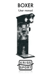
Game Adjustment Table
Adjustment
Number
(Piayer 3)
Description
Factory Setting
(Piayers 1 & 2)
(Piayer 4)
1
AD01
AD02
AD03
AD04
ADOS
AD06
AD07
ADOS
AD09
AD10
AD 11
AD12
AD13
AD14
AD15
AD16
AD17
AD1'8
AD19
EAd20
EAd 21
EAd22
EAd23
EAd24
EAd25
EAd26
EAd27
EAd28
EAd29
EAd30
EAd31
EAd32
EAd33
EAd34
EAd35
EAd36
EAd37
E Ad 36
EAd39
EAd40
EAd 41
EAd42
EAd43
EAd44
EAd45
EAd46
EAd47
EAd48
EAd49
EAd 50
EAd 51
EAd52
EAd 53
EAd54
EAd55
EAd56
EAd 57
EAd 58
EAd 59
10
Replay/Manual
Start Replay/Level 1 Re play
Levels Replay/Level 2 Replay
Leval 3 Replay
Level 4 Replay
Extra Easy Aulas
Easy Rules
Factory Rules
Hard Rules
Extra Hard Aulas
Novelty Ru les
5 Bali Rules
Addaball Aulas
Standard/Cus1om Pricing
Tlme Setting
Coin Reset
Audits Reset
Restore Hlscr
Expand Adjus1ments
Awards Replay
Awards Special
Match Feature
Balls/Game
Warnlng Tilt
Maximum Extra Balls
Credits Umit
Scores Hlghest
Credits Hlgh Score 1
Credits High Score 2
Credits High Soore 3
Credits High Score 4
Hlgh Score 1 Bacl<up
High Score 2 Backup
High Score 3 Backup
High Score 4 Backup
High Score Reset Every
Free Play
Left Coin Pulses
Righi Coin Pulses
Center Coin Pulses
Pulses For Credit
Pulses For Bonus Credit
Message Custom
Text
Attract Mode Music
Ughts
General Scores
General Tlmer
General Memory
Playboy Targets
Extra Ball6x
Playboy Percent
Laser Kick
Knooker Alarm
Mansion Memory
Pinball Memory
Auto Special
Risque Sound
Factory Restore
10%
2,300,000
01
.
.
.
.
-
.
ON
ENGUSH
ON
FACTORY
FACTOAY
FACTOAY
FACTOAY
HARD
ON
FACTOAY
FACTORY
ON
BALL
BALL
ON
ON
OFF
1
_,
'=
J.~
...
,
-
a()JO'Ji
'3
.
.
OFF
OFF
ON
OFF
OFF
OFF
OFF
OFF
USA 1
ON
OFF
OFF
OFF
OFF
CREDITS
CREDITS
ON
03
01
03
30
ON
03
00
00
00
5,000,000
4,000,000
3,000,000
2,500,000
700
OFF
-
1 · ·•
--
~
0~
.t ~:q::
..fiN" 0~~
L"'-'FuF;-
oFF
tJFF
S
{)~f
~>1E.DE..PJ
tJN
QPoP
()J=F
EJF~
?
CJt ~!.' t'T S
ct.f!r .,~
(Jf
2.
~~
fiN
3
:
2
t
a
5.tt0,(J{i(J
l-11 ()Bt; r(J/. ~
~, LJIJO,aoo
fl.t 5DDilJU J
'1 (
OFF
}
.,f~,.,.
!l ad 1~
~""e<J. en Prtts
Otv
EIVGL\S.i-1
JV
~~~\·V
F oe!~ o~1
Fa~.
of'
P~c.to<'y
P'Q(~V
P ~:4- r
'
}JII
~rf'~
t:JN
e:JPF
-
Ad 04 L.evel3 Replay (Fixed Only) • Wlth Ad 01 set forflxed, adjust Replay 3 leve! to between 100,000 and 9,900,000.
To dlsable Replay 3, lower the settlng to 00.
Ad 05level 4 Replay (Fixed Only) • With Ad 01 setfor flxed, adjust Replay 41evel to between 100,000 and 9,900,000.
To dlsable Replay 4, lower the settlng to 00.
SINGLE-FUNCTION DIFFICULTV ADJUSTMENTS (Ad 06 to 10)
Any one of these ftve INSTALL adjustments may be activated to automatlcally select settings for multiple
adjustments affecting game dlfflculty. After activation, the lndivldual adjustments may be readjusted If deslred.
Refer to lnstall Adjustment Table for details.
Ad 06 Extra Easy Ruies ·Set to ON or OFF.
Ad 07 Easy Rules - Set to ON or OFF.
Ad 08 Factory Rules - Set to ON or OFF.
Ad 09 Hard Rules - Set to ON or OFF.
Ad 10 Extra Hard Rules - Set to ON or OFF.
.'
NOVELTV / 5-BALI../ADD-A-BALL RULES (Ad 11, 12, 13)
One ofthese three INSTALL adjustments may be activated to automatically select settings for multiple adjustments.
After activation, the indivldual adjustments may be readjusted if deslred.
NOTE: When more than one of these features ls required (for example, Add-A-Bali rules with 5-Ball Play) set only
one of these rule features and then change additlonal adjustments. For the Add-A-Bali and 5-Ball Play example:
Ad 13 Add a Bali Rules = On
E Ad 23 Balls per Gama = 5
E Ad 47 General Scores= Hard
E Ad 48 General Tlmer = Hard
E Ad 49 General Memory = Factory
E Ad 50 Playboy Targets = Factory
E Ad 51 Extra Ball5x = On
E Ad 52 Playboy Percent =Hard
E Ad 53 Laser Klck = On
By settlng the game up ln this fashlon, ali speclals and replay levels will award an extra bali. However, because
the operator desires 5-ball play, ali game play features are set to 5 Bali settlngs.
Ad 11 Novelty Play Rules- Set to establlsh settlngs for no free play or extra balls; ON or OFF. If ON the following
settings are establlshed:
Ad 01 Manual Replay = Fixed
Ad 02 to Ad 05 Replays 1 to 4 = Off
E Ad 20 Awards Replay = Audit
E Ad 21 Awards Special = Score
E Ad 22 Match Feature = Off
E Ad 25 Maximum Extra Balls = oo
E Ad 27 Scores Hlghest = Off
E Ad 28 to 31 Credits Hlgh Score=OO
Ad 12 5-Ball Play Rules- Set to establish recommended settlngs for 5-ball play; ON or OFF. If ON the followlng
settlngs are establlshed
Ad 01 Manual Replay = 07%
Ad 02 Replay Start = 3,000,000
Ad 03 Replay Levels = 01
E Ad 23 Balls Per Gama = 05
E Ad 47 General Scores = Hard
E Ad 48 General Timer = Hard
E Ad 49 General Memory = Factory
E Ad 50 PlayboyTargets = Factory
E Ad 51 Extra Ball5x = On
E Ad 52 Playboy Percent = Hard
E Ad 53 Laser Kick = Factory
E Ad 55 Mansion Memory =Player
E Ad 56 Pinbali Memory =Player
11
INSTALL ADJUSTMENT TABLE
lnstail
Adjustment
E Ad 47 General Scores
E Ad 48 General Tlmer
E Ad 49 General Memo_ry
E Ad 50 PlayboyTargets
E Ad 51 Extra Bali 5x
E Ad 52 Plavbov Percent
E Ad 53 Laser Kick
E Ad 55 Mansion Memorv
E Ad 56 Plnball Memorv
Extra Eaay
AdOS
Ad07
Eaay
AdOS
Factory
Ad09
Hard
Ad 10
Extra Hard
EASY
EASY
EASY
EASY
ON
EASY
EASY
PLAYER
PLAYER
FACTORY
EASY
EASY
FACTORY
ON
FACTORY
EASY
BALL
PLAYER
FACTORY
FACTORY
FACTORY
FACTORY
ON
FACTORY
FACTORY
BALL
BALL
HARD
FACTORY
HARD
FACTORY
OFF
HARD
HARD
BALL
BALL
HARD
HARD
HARD
HARD
OFF
HARD
HARD
NONE
NONE
Ad 13 Add-A-Bali Rules- Set to dlsable awardlng of credits, replaclng replay and Special awards wlth an extra
bali; ON or OFF. If ON the following settlngs are establlshed:
E Ad 20 Awards Replay = Extra Bali
E Ad 21 Awards Special = Extra Bali
E Ad 22 Match Feature = OFF
E Ad 27 Scores Hlghest = OFF
E Ad 28 to 31 Hlgh Score Credits = 00
GAME PRICING (Ad 14 and E Ad 38 to 42)
There are two methods avaDable for coin switch programmlng; Standard and Custom. Standard pricing uses a
single adjustment (Ad 14) to select a prlclng scheme shown ln the Standard Prtclng Table. Custom priclng ls
used to select additlonal priclng schemas detlned by expanded adjustments E Ad 38 to 42. ln arder to program
E Ad 38 to 42·, Ad 14 must be set to CUSTOM and Ad 19 must be set to ON for expanded adjustments.
Wlth Ad 14 set to CUSTOM and expanded ad}ustments selected, E Ad 38, 39, and 40 represent coin switch pulses
for the left, right, and center coin slots. E Ad 41 prescribes the number of pulses requlred for one credit. For
example, If E Ad 38 was set to 02 and E Ad 41 to 01 a coin ln the Jeft slot would produce two credits. Further, If E
Ad 38 was set to 01 and E Ad 41 to 02, two coins ln the left slot would be requlred for one credit.
E Ad 43 may be set to post bonus credits wh en a minimum amount of coins are lnserted at one tlme. For example,
IfE Ad 38 was set to 01, E Ad 41 to 01 andE Ad 42 to 04, one credit would be posted for each of the tlrst three
coins ln the left slot and two credits for the fourth coin.
Ad 14 Standard/Custom Prlclng- Set for the deslred prlclng schema from the Standard Pricing Table as indlcated
ln the Player 1 and 2 dlsplays. For Custom Prlclng, set to CUSTOM. When set to CUSTOM, Expanded adjustments
E Ad 38 to 42 are utillzed to taller each lndlvldual coin chute.
E Ad 38 Left Coin Swltch Pulses • Set the number of pulses reglstered for closure of the left coin switch; 00 to
99.
E Ad 39 Rlght Coin Switch Pulses • Set the number of pulses reglstered for closure of the right coin switch; 00
to99.
E Ad 40 Center Coin Swltch Pulses - Set the number of pulses reglstered for closure of the center coin swltch;
00 to 99.
E Ad 41 Coin Switch Pulses Requlred for 1 Credit- Set the number of coin switch pulses requlred to post one
credit; 00 to 99.
E Ad 4~ Coin Switch Pulses Requlred for Bonus Credit- Set the number of coin switch pulses requlred to award
a bonus credit; 00 to 99.
12
STANDARD PRICING TABLE
(_
Coin Mechs
Ad 14 Standard
Priclng Select
Plays/Coins
Left
Center
Rlght
Left
Center
Rlght
2S~
$1.00
25~
1 PLAY/1COIN
4 PLAY/1 COIN
1 PLAY/1 COIN
USA2 4 COINS3PLAYS
2S~
$1.00
25e
1 PLAY/2COIN 3 PLAY/1COIN 1 PLAY/2COIN
2 PLAY/3COIN
2 PLAY/3COIN
3 PLAY/4COIN
3 PLAY/ 4COIN
USA3 2 COINS 1 PLAY
25~
$1.00
25~
1 PLAY/2COIN
USA4 2COINS 1 PLAY
1COIN BUY-1N
2se
AUSTRIA COl NAGE
SSCH
AUSTRAUA COl NAGE
20t
UKCOINAGE
10P
SP
10P
SWISS 1
SWISS2
1 SFR
2SFR
SSFR
BELGIUM COINAGE
20/
20/
20/
1 PLAY/1COIN
1 PLAY/1COIN
1 PLAY/1COIN
~ERMAN SOM 7 PLAYS
1
10M
20M
SOM
1 PLAY/1COIN
7 PLAY/5COIN
2 PLAY/1COIN
8 PLAY/3COIN
7 PLAY/1COIN
f]ERMAN SOM 9 PLAYS
2
10M
20M
SOM
1 PLAY/1COIN 3 PLAY/ 1COIN 9 PLAY/1COIN
3 PLAY/2COIN 7 PLAY/2COIN
5 PLAY/3COIN 10 PLAY/3COIN
7 PLAY/4COIN 14 PLAY/4COIN
9 PLAY/ 5COIN
1
2
USA1
4
1COIN 1PLAY
10SCH
NETHERLANO COINAGE 1 Guilder
2 PLAY/1COIN
1 PLAY/2COIN
2se
2 COINS FOR THE 1st PLAY
1PLAY/1 COIN ONLY DURING BUY-IN
10SCH
1 PLAY/2COIN 2 PLAY/1COIN 2 PLAY/1COIN
2 PLAY/3COIN 3 PLAY/2COIN 3 PLAY/2COIN
3 PLAY/4COIN
$1.00
1 PLAY/2COIN
3 PLAY/1COIN
1 PLAY/ 1COIN 5 PLAY/1COIN
1 PLAY/1COIN
Same as German 1
Same as German 2
1 Guilder 1 PLAY/2COIN
1 PLAY/2COIN
SWEOEN COINAGE
1KR
SKR
2KR
1 PLAY/3COIN
2 PLAY/ 5COIN
FRANCE COINAGE
1/
Sf
10/
1 PLAY/3COIN 2 PLAY/ 1COIN
2 PLAY/5COIN
4 PLAY/ 1COIN
ITALY COINAGE
SOOL
SOOL
1 PLAY/1COIN
1 PLAY/1COIN
SPAIN COINAGE
25P
100P
1 PLAY/ 1COIN
5 PLAY/1 COIN
JAPAN COINAGE
100Y
2 PLAY/ 1COIN 2 PLAY/ 1COIN
1 PLAY/ 1COIN
13
CUSTOM PRICING TABLE
Coin Mechs
Rlght
Center
Lett
25e
25~
$1.00
SSCH
10SCH
10SCH
20~
$1 .00
--
10P
10P
SOP
Adjustment Numbers
39
40
38
Plays/Colns
14
19
1/25e 3/50tt
112se 5/$1 .00
1/25e/ 6/$1 .00
Custom
Custom
Custom
ON
ON
ON
01
01
05
01
01
05
1/10 SCH
1/10 SCH 4/30SCH
Custom
Custom
ON
ON
01
04
Custom
Custom
ON
ON
Custom
Custom
ON
ON
112oe
2/$1 .00
1 /60~
1/10P 6/50P
1/20P 3/50P
41
42
04
04
20
01
01
04
02
02
08
02
08
02
06
00
00
01
01
05
05
00
00
01
03
00
05
01
01
01
01
05
05
01
02
05
05
04
20
ADDITIONAL GENERIC FEATU RES
Ad 15 Average Bali Tl me - Maintains average bali tlme close to 65 seconds. Every 700 (vary with E Ad 36} games,
average bali tlme ls checked. If greater than 65 seconds, E Ad 53 ls set to HARD. If less than 65 seconds, E Ad
53ls set to EASY.
Ad 16 Coin Reset- When enabled (set to ON} ali coin and pald credit totals will be reset to zero when STEP ls
depressed.
Ad 17 Audits Reset - When enabled (set to ON) ali audit totals except for coins and pald credits will be reset to
zero when STEP ls depressed.
Ad 18 Restore Hlgh Score - When enabled (set to ON} the Hlgh Score Levels and assoclated Initiais wDJ be
restored to backup settlngs when STEP is depressed .
Ad 19 Expand Adjustments - When set to OFF, depresslng the STEP push-button advances directly to E Ad 59,
FACTORY RESET. When set to ON, depressing the STEP push-button sequences through the expanded
adjustments. When exiting from expanded adjustments, this functlon is reset to OFF for the next lime that
adjustments are requlred.
E Ad 20 Awards Replay - Set for replays to award: CREDIT, EXTRA BALL, or AUDIT (no award but recorded
ln the audit totals).
E Ad 21 Awards Special - Set for Special to award: CREDIT, EXTRA BALL, or SCORE LEVEL
E Ad 22 Match Feature- Set Match ON or OFF.
E Ad 23 Balis Per Game - Adjust the number of balls per game; 2 to 9.
E Ad 24 Warnlng T11t - Adjust the number of plumb bob tUt switch closures before the ball in play is tilted; 1 to 3
or OFF.
E Ad 25 Maximum Extra Balis · Ad just for the maximum number of extra balls that may be accumulated per bali;
1 to 9 or OFF.
E Ad 26 Credits Umlt - Ad just the maximum number of credits that may be posted; 5 to 99.
14
-
HIGH SCORE LEVELS (E Ad 27 through 36)
There are four hlgh score levels wlth assoclated player Initiais thal are dlsplayed durfng the attract mode. This
provldes a hlgh-score-to-date feature. When players exceed these levels, the player Initiais may be entered to
replace the prevlous ones These Javels may be adjusted to award credits and to be reset to backup vaiLles after
a selected number of games.
E Ad 27 Scores Highest- Set to enable or dlsable the four high score levels; ON or OFF.
E Ad 28 Credits Hlgh Score Level1 - Adjust the number of credits awarded for exceedlng level1 (the hlghest of
the four levels); 0 to 9.
E Ad 29 Credits Hlgh Score Leval 2- Adjust the number of credits awarded for exceeding level 2; 0 to 9.
E Ad 30 Credits Hlgh Score Level 3- Adjust the number of credits awarded for exceedlng leval 3; 0 to 9.
E Ad 31 Credits Hlgh Score Levet 4- Adjust the number of credits awarded for exceedlng level 4; 0 to 9.
E Ad 32 High Score 1 Backup -Adjust the backup scorelevel to whlch level1 (the hlghest of the four levels) may
be reset.
E Ad 33 Hlgh Score 2 Backup- Adjust the backup score level to whlch level2 may be reset
E Ad 34 Hlgh Score 3 Backup - Adjust the backup score level to whlch level 3 may be reset
E Ad 35 Hlgh Score 4 Backup -Ad just the backup score leval to whlch levet 4 may be reset
E Ad 36 High Score Reset Every- Ad just the number of games between automatlc resets of hlgh scorelevels to
backup settlngs and bali tlme averager adjustments; 100 to 900 or OFF (no reset or adjustment).
E Ad 37 Free Play- When set to ON, no coins are requlred for games.
E Ad 38 to 42 Custom Prlclng - Described prevlously ln Gama Priclng.
E Ad 43 Message Custom - When desired, this functlon ls used to establlsh a custom message perfodlcally
dlsplayed durlng the att.ract mode. Set the feature to CHANGE using the Credit button and depress STEP. The
letter Ais indicated ln the flrst position of the Player 1 dlsplay. Vary theletter by operatlng the left and rlght flippers.
With the deslred latter lndlcated, depress the CREDIT button to lock ln the latter and advance to the next dlsplay
character. Repeat this procedure untll the deslred message ls indicated ln the Player 1 and 2 dlsplays. At this tlme,
depress the STEP push-button switch to advance to E Ad 44.
NOTE
To Jock ln the custom message, the game must be returned to Game Overby depresslng STEP wlth E Ad 59
dlsplayed.
E Ad 44 Engllsh/French/ German Text- Select Engllsh, French, or German for dlsplay during Audits, Adjustments,
and Game Diagnostics.
E Ad 45 Attract Mode Music- Set to ON (once avery seven attract mode cycles), OFTEN (every attract mode
cycle), or OFF.
E Ad 54 Knocker Alarm-When the game ls flrst powered up and after lt has passed lt's self test, any suspect
switches or colis are dlsplayed ln the Player Dlsplays. Wlth this 1eature enabled (set to ON), the Knocker ls pulsed
to alert the location dttendant if there are any suspect switches or colis. With this feature dlsabled (set to OFF),
the Knocker ls not pulsed durfng Indications of suspect switches or colis.
15
GAME SPECIFIC FEATURES (E Ad 46 TO 54)
E Ad46 Flash Lamps- Set to ON or OFF.When set to ON the Aash Lamps are active, wh en OFF the Aash lamps
do not flash.
E Ad47 General scores- Set to EASY,FACTORY or HARD.
Feature Affected
Hard
Factory
Easy
Center Bank Ut
Center Bank Unllt
Playboy Ut
Playboy Unlit
Lock Bali
Champagne Kick
laser Kick
Left Orain
Rlght Drain
Aeturn lanes
Drop Targets
lamps
2000
200
5000
200
3000
3000
25K
25K
20K
5000
10000
20K
3000
500
5000
500
5000
5000
25K
25K
20K
5000
10000
20K
5000
1000
5000
1000
10000
10000
25K
25K
20K
5000
10000
20K
E Ad48 General Tlmer- Set to EASY,FACTORY or HARD.
Feature Affected
Easy
Factory
Hard
Mansion Shot
Drop Targets 100K
Drop Targets 75K
Drop Targets 50K
Drop Targets 25K
2x Playfleld Scores
3x Playfleld Scores
4x Playfleld Scores
5x Playfield Scores
22
7
9
10
11
22
20
18
14
20
6
18
5
6
7
9
7
9
10
20
18
14
12
18
14
12
10
The number expressed ln the dlfflculty settlngs lndicates the tirne duratlon of the feature ln seconds.
E Ad 49 General Memory- Set to EASY,FACTORY or HARO.
Feature Affected
Easy
Fa ctory
Hard
PLAYBOY
Top lanes
Special
Player
Bali
Bali
Bali
Bali
Bali
None
None
Bali
BALL:Each player bullds up the feature for his own lndividual use and the feature accumulates from bali to bali
withln a gama.
PLAYER:The feature builds up ln value for the use of ali players throughout the game.
NONE:The feature resets after avery bali.
E Ad 50 Playboy Targeta-Set to EASY,FACTORY or HARD.When set to EASY,striklng any target will spot a latter
(P-L-A-Y-B-0-Y) startlng from the bottom targetWhen set to FACTORY, strlklng any UNUT Target will spot a
latter beglnlng with the bottom target.When set to HARD any unllt target will spot the letter hlt.
E Ad51 Extra bali sx-Set to ON or OFF.When set to ON, completlng the Top lanes 5 times llghts one of the
outlanes that award an Extra Bali.
16
E Ad52 Playboy Percent-Set to EASY,FACTORY or HARD.
Completlng Playboy Awards
Easy
Factory
Hard
50K
100K
Outlanes Ute SOK
Bonus Hold 50K
Extra Bali
1 Million
10%
10%
20%
20%
20%
20%
10%
10%
30%
25%
25%
25%
15%
15%
20%
15%
5%
5%
E Ad53 Laser Kick- Set to EASY,FACTORY or HARD.
EASY-Starts lit on each bali and completlng one lit ramp will rellte the feature.
FACTORY-Starts lit on each bali and completing two lit ramps will rellte the feature.
HARD-Starts lit on the flrst bali only, once used,the feature must be re-lit by completlng both ramps.
E Ad54 Knocker Alarm-Prevfously descrfbed at the end of Generlc Gama Features.
E Ad55 Mansion Memory-Set to BALL,PLAYER or NONE.
BALL:Each player builds up the feature for his own lndlvldual use and the feature accumulates from bali to bali
wlthln a game.
PLAYER:The feature bullds up ln value for the use of ali players throughout the game.
NONE:The feature resets after avery bali.
.. .
,·
E Ad56 Plnball Memory-Set to BALL.PLAYER or NONE.
BALL:Each player builds up the feature for his own lndMdual use and the feature accumulates from bali to bali
withln a game.
PLAYER:The feature buUds up ln value for the use of ali players throughout the game.
NONE:The feature resets after avery bali.
E Ad 57 Auto Special-Set to ON or OFF. When ON ,every 100 games this automatlcally determines the number of
times the Drop Targets must be completed to award a Speclal.(3,4,5 or 6 times) When OFF the Drop Targets must
be Cf>mpleted 6 times to award a Special.
E Ad 58 Risque Sound a-Set to ON or OFF. When OFF moanlng sounds actlvated by certain swltches and features
will be replaced wlth normal plnball sounds.
E Ad 59 Fa ctory Restore-Depresslng STEP without changlng the value shown ln the Player 4 Dlsplay locks ln any
custom message set wlth E Ad43 and returns the game to GameOver.Set the value to ON and depress STEP switch
to revert ali game adjustments to factory settings, clear the Custom Message and return to Game Over.
17
GAME DIAGNOSTICS
The Data East Plnball system provldes tests for sounds, digital dlsplays, lamps, swltches, and solenolds. Each
feature may be tested manually or automatlcally uslng the STEP and FOAWARO/REVERSE push-button swltches
inside the coin door and the Ga me Start push-button switch on the front of the cabinet. The automatic tests may
be used for a quick verification of automatlc test functlons and the manual tests, for troubleshootlng.
Du ring gama play, activation of switches and operation of colis with associated switches are monitored. if a switch
ls not made for 100 games lt is consldered bad. When operation of a coil should close or open a swltch and does
not, the coU ls consldered bad. Each tlme the game is powered up, bad switches and colis (If any) are reported;
to alert the location attendant, the credit knocker ls pulsed. Note that reporting of an unused switch does not
constitute a problem and that a bad coll could mean that the associated switch requires adjustment.
Wirlng to switches, solenoids and controlled lamps uses color-coded wlres that basically follows a resistor
color-code schema for the eight rows and eight columns. During the switch tests and during the dlscrete lamp
test, Identification of the color of the row and column wlres are lndlcated ln the Player 3 Dlsplay. For example,
maklng the rlght coin switch durlng the Switch Test results ln th~ switch functlonal name (RIGHT COIN) shown ln
the Player 1 and 2 Dlsplays, the row (94) and column (51) wlre color codes shown ln the Player 3 dlsplay, and the
switch number shown in the Player 4 dlsplay. The 94 code (refer to the chart below} lndlcates a White wlre with
Yellow strlpe for the row wlre and the 51 code indicates a Green wire wlth Brown strlpe.
O=Biack
1 =Brown
2=Red
3=0range
4=Yellow
S=Green
6=Biue
7=VIolet
S=Grey
9=Whlte
ENTERING DIAGNOSTICS
Wlth the game in the game-over mode, open the coin door and make sure that the FORWARD/REVERSE
push-button switch ls set to REVERSE (down) and depress the STEP push-button switch. The Player displays will
show the tollfree Customer Service number 1-800-KiCKERS, that is 1-800-542-53n (outside Illinois) and the toll
number (312) 345-7700 (inside Illinois). this lndicates entry lnto gama diagnostics.
SOUND TESTS
The Data East Pinball sound system produces true digital stereo sound on left and right speakers and mono on a
center speaker. Durlng Sound tests, the Player 1 and 2 displays show the sound board circuit under test and the
corresponding sounds are produced. Referto the Sound Test Chart for the sound circuits displayed and the sounds
produced.
The sine wave functions allow verification that ali channels are functionlng properly and that the speaker
connections are correct. Speaker Phase Testlng procedures follow for checklng speaker connections.
19
SOUND TEST CHART
Auto/Ma nuai Tests
(Piayer 1 & 2)
Sounda Produced
LEFTSINE
CENTER SINE
RIGHTSINE
VOICE ROM1 (Loc F6)
60 CYCLE TONE (Left Speaker Only)
60 CYCLE TONE (Ali speakers)
60 CYCLE TONE (Right Speaker Only)
''THAT'S BEAUTIFUL", "OOHI", HORN BLAST "MMM .. I"
CHIMPANZEE SOUNDS
BIAO CALL, "OOHI", "CAIO BABY" HORN BLAST.
MUSIC
VOICE ROM2 (Loc F4)
MUSIC TEST (Sound ROM Loc F7)
Automatlc Test
Wlth Customer Service telephone numbers dlsplayed, depress the STEP push-button switch. Player 1 and 2
dlsplays lndlcate SOUNDS AUTO and the system sequences through the test producing the sounds indicated in
the Sound Test Chart.
Manual Test
Operate the STEP push-button swltch during the Automatic tests untll SOUNDS MANUAL ls lndlcated ln the Player
1 and 2 displays. Depresslng the Game Start push-button swltch allows you to advance through each sound
functlon.
Speaker Phase Testlng
Connections to each of the three speakers are polarlzed and each must be connected approprlately for the best
quallty sound. If one speaker has the positive and negative connections reversed with respect to the ether two,
bass frequencles wUI not be produced property and the overall sound quallty will be poor.
To test for proper speaker phaslng., use the manual sound test to cycle through the Left, Center, and Rlght Sine
functlons. If the Center Sine produces more volume and bass than the Left and Rlght Slnes, the speakers are
connected property. If it produces the same or Jess, one speaker ls connected lmproperty. To lsolate and correct
reversed speaker connections, one of two methods may be used.
1. Check each speaker for polarity markings. If the speakers have polarlty marklngs, verity that the slngle-color
wire (BLK, YEL or RED) is connected to the negative (·) terminal.
2. Dlsconnect the speaker output connecter from the Sound Board and connect a 1.5-volt battery across each
speaker pair one at a tlme while observlng the speakers. Make sure that the positive battery terminal Js
connected to the positive lead (CN1-pln 1• 3, or 6) each tl me. As the connectlon ls made, check speaker
cene movement; proper connections are lndlcated by outward movement.
20
DIGITAL DISPLAY TEST
Digital dlsplays are drlven by digit and segment driver circuits. Digit drivers sequentlally select lndlvlduaJ character
positions (Piayer 1 and 2 dlsplays} and digit positions (Piayer 3 and 4 dlsplays). Segment drivers (16 for Player 1
and 2 characters; 7 for Player 3 and 4 digits) select the lndlvldual segments of each position.
Automatic Test
To enter Dlsplay tests, operate the STEP push-button swltch from the Sound Manual test. Player 1 and 2 dlsplays
lndlcate DISPLAY AUTO. The dlsplays will sequence from ali ZEROS to ali ninas ln the four dlsplays. Next ali
segments are lit for each digit position in sequence.
Manual Test
Operate the TEST push-button swltch from the automatlc test; Player 1 and 2 dlsplays lndlcate DISPLAY MANUAL
and then display ZEROS ln ali positions. Operate the Game Start push-button swltch to cycle through each portion
of the test
21
Swltches
Swltches are conflgured ln an 8 x 8 rnatrlx of columns (swltch drives) and rows (swltch retums) wtth up to 64
swltches possible. The swltch tests lnclude three parts; swltch test, active swltches, and bad swltches. Row and
column wlre colors are lndlcated ln each test uslng correspondlng resistor color code numbers.
Switch Test
From the Dlsplay ManuaJ test, operate STEP push-button switch. Player 1 and 2 dlsplays lndlcate SWITCH TEST.
a ose each swltch and observe the dlsplays. The Player 1 and 2 dlsplays willlndlcate the switch name, the Player
3 dlsplay lndlcates the row and column wire colors, and the Player 4 dlsplay lndlcates the swltch number. When
a swltch ls released, the name and number dlsappear untU another switch is closed or the test ls exited.
Active Swttches
Operate the STEP push-button swltch from the Swltch Test. Player 1 and 2 Dlsplays lndlcate ACTIVE SWITCHES.
If any swltches are stuck closed (or made from the presence of a bali), the Player 1 and 2 dlsplays sequence through
swltch names, the Player 3 dlsplay lndlcates the row and column wlre col ors, and the swltch numbers arelndlcated
ln the Player 4 dlsplay. This cycle continues untll ali swltches are cleared or untU the STEP push-button swltch 19
depressed.
Bad Swttches
Operate the STEP push-button swltch from the Switch Test Player 1 and 2 Dlsplays lndlcate BAD SWITCHES.
Durlng game play, the system keeps track of the last game ln whlch each switch was made. Should a swttch not
be made for 100 games, Jt ls consldered to be bad. If there are any, the Player 1 and 2 dlsplays sequence through
swltch names, the Player 3 dlsplay lndlcates the row and column wlre colors, and the swltch numbers are lndlcated
ln the Player 4 dlsplay. This cycle continues untll the STEP push-button switch ls depressed.
SWITCH MATRIX CHART
~
4
1
2
3
5
8
7
8
) GAN-BAN GAN-RED GRN-ORN GRN-YEL GRN-BLK GRN-BLU GRN-VIO GRN-GRV
(51} QSS (52} Q54 (53} Q53 (54} Q52 {50} Q51 {56) 050 (57} Q49 (58) Q48
1WHT-BRN
(91)
Plumb
Tilt
2WHT-RED
(92)
Not
Used
3WHT-ORN
(93)
Credit
Button
4WHT-YEL
(94)
Right
Coin
5WHT-GRN
(95)
Center
Coin
6WHT-BLU
(96)
Left
Coin
7WHT-VIO
(97)
Siam
Tdt
--
8 WHT-GRY
(98)
Not
Used
1
Not
Used
9
Outhole
2
3
4
5
6
7
10
Trough
#1
Trough
#2
Trough
#3
Shooter
Lane
Left
EOS
Left
OuUane
17
Left Top
La ne
25
p
Target
33
Ctr3
Bank-Ut
41
Cntr.Top
Cntr3
L
Left
Return l E Lane 26 Target 34 Bank-Mid ~
4
Drop 1
Top
Drop2
Center
49
50
A
RlttTop
Cntr3
Drop3
Right
ne ... ~ Target
Bank-Rt. ~ Bottom
Outlane
s
11
2ï
35
4
51
1
12
13
14
15
RJght
Return
Left
Sllngsht
Rlght
Sllngsht
20
21
22
Champ.
Klcker ~
2
Grotto
Rlght
1
E S 16
24
Ramp
Center
Ramp
Rlght
Left
Splnner
Grotto
2
e
2
29
311
31
Ramp
Left 3~
1st Y
Target 3€
Not
Used
8
Target
VUK
0
Target
2nd Y
Target
Not
Used
37
a
3
39
44
45
Left
Pop
Center
Pop
Rlght
Pop
46
4/
Not
Used
Not
Used
Not
Used
57
58
59
Not
Used :,
Not
Used
Not
Used
Not
Used 61
5~
Not
Used
Not
Used
Not
Used
53
54
S'ï
Not
Used
Not
Used
Not
Used
60
62
63
40
8
48
56
64
(*) 2 DIGIT NUMBER IN PARENTHESES INDICATES RESISTOR/WIRE COLOR CODE NUMBER DISPLAYED DURING DIAGNOSTICS.
22
,.
Number Description
01*
02
03
04*
os•
06*
07*
08
09
•
PlumbTIIt
Not Used
Credit Bunon
Right Coin
Center Coin
Left Coin
Siam Tilt
Not Used
Not Used
Part No.
Number Description
500-5023-00
10
11
12
13
14
15
500-5097-00
180-5024-00
180-5024-00
180-5024-00
180-5022-00
16
17
18
19
20
21
22
23
24
25
26
27
28
29
30
31
32
33
34
35
36
37
38
39
40
41
42
43
44
45
46
47
48
49
50
51
52
Part No.
Out Hole
Trough #1
Trough #2
Trough #3
Shooter Lane
left Fllp. Instant lnfo.
Left EOS
Rlght Alp. Instant lnfo.
Rlght EOS
Left Outlane
left Retum lane
Rlght Outlane
Alght Retum lane
left Sllngshot Trlgger Sw.
Left Sllngshot Point Sw.
Rlght Sllngshot Trigger Sw.
Rlght Sllngshot Point Sw.
Champagne Klcker
Grotto 1
Left Top Lane
Center Top lane
Rlght Top lane
Ramp Center
Ramp Alght
Left Splnner
Grotto 2
Ramp Left
P -Target
L -Target
A -Target
tst Y -Target
B -Target
0 -Target
2nd Y -Target
Not Used
Center 3 Bank Left
Center 3 Bank Middle
Center 3 Bank Right
Not Used
180-5011-00
180-5009-00
180-5009-00
180-5010-00
500-5142-00
180-5026-00
180-5018.00
180-5026-00
180-5018.00
500·5143-00
180·5003-00
515-5138-00
180-5003.()0
180·5054..()0
180-5055.()0
180-5054..()0
180-5055..()0
180-5040..()0
180-5028.00
515-5138-00
515-5138-00
515-5138-00
180·501 0-00
180-5010-00
180·5004-00
180-5040-00
180-5034-00
515-5124-18
515-5124.()8
515-5124-18
515·5124-18
515-5124-1 8
515-5124-18
515-5124-18
VUK
180·5041-00
180·5036-00
180-5036-00
180-5036-00
180-5025.()1
180-5025.()1
180-5025.()1
Left Pop Bumper
Center Pop Bumper
Rlght Pop Bumper
Drop 1 (Top)
Drop 2 (Center)
Drop 3 (Bottom)
Not Used Thru 64
515-5124-18
515-5124-18
515-5124-18
*INDICATES CABINET SWITCHES.
23
LAMPTESTS
Controlled lamps are conflgured ln an 8 x 8 matrix of columns Qamp drives) and rows Qamp retums) with up to 64
lamps possible. The lamp tests lnclude four parts, ali lamps, lamp retum (row), lamp drive (column), and dlscrete
(lndivldual) lamps. Row and column wlre col ors are lndlcated ln the dlscrete lamp test uslng corresponding resistor
color code numbers.
Ali Lamos
From the Bad Switch test, operate the STEP push-bunon switch. Player 1 and 2 displays indicate ALL LAMPS and
ali controlled lamps wUIIIght.
Lamo Returns
From lhe ALL LAMPS test, depress the STEP push-bunon switch. Player 1 and 2 dlsplays lndicate LAMP ROWS
and the Player 4 dlsplay lndlcates 01 for row 1. Ali controlled lamps ln row 1 should be lit. Operatlng the Gama
Start push-button swltch cycles through each of the rows separately.
Lamp Drives
From the LAMP ROWS test, depress the STEP push-button swltch. Player 1 and 2 dlsplays lndlcate LAMP
COLUMNS and the Piayer 4 dlsplay lndlcates 01 for column 1. Ali controlled lamps ln column 1 should be lit.
Operatlng the Game Start push-button switch,cycles through each of the columns separately.
Discrete Lamo
From the LAMP COLUMNS test, depress the STEP push-bunon swltch. Player 1 and 2 dlsplays indicate LAMP
TEST and then the name asslgned ta lamp 01; the Player 1 and 2 dlsplays lndlcate the lamp name, the Player 3
dlsplay lndlcates the row and column wlre colors, and the Player 4 dlsplay lndicates 01. Lamp 01 should llght.
Wlth the FORWARD/REVERSE push-button swltch ln the FORWARD (up) position, operatlng the Game Start
push-button switch selects higher-numbered lamps; with it ln the REVERSE (down) position, Game Start selects
lower-numbered lamps.
LAMP MATAIX CHART
~
1
2
YEL-BRN
YEL-RED
)
(41) 071 (42) 070
1RED-BRN
(21) 072
Playboy
1
2RED-BLK pLayboy
{20) 073
3RED-ORN
(23) 074
plAyboy
4RED-YEL
(24) 075
plaYboy
2
3
4
5RED-GRN playBoy
(25) 076
6RED-BLU
(26) 077
7 RED-VIO
(27) 078
8RED-GRY
(28)) 079
24
5
playbOy
Miss
July 50k
9
3
4
YEL-ORN YEL-BLK
(43) 069 (40) 068
Photo
Shoot 1
25
Photo
Special
~t.Green
Arr.Tar.
c
14
22
3
Top Left Splnner
Mult.AII
playboY
BunnyHop X-Bali
Scores
15
7
23
3
6
Lt."H"
Lane
8
7
YEL-VIO
(47) 065
8
YEL-GRY
(48) 064
Up At.
Man.Pty
plnball
!Mansion
Pinbali
49
57
At. Score
U.Score ~nsion
Miss
Lock
Photo
Bonus
Aug.100k
PBValue
PBValue
Ball#l
Shoot 2
Hold
26
34
10
5S
18
42
50
Right
~aNs lon
Left
Lock
Miss
Photo
Plarr
Peacock IPeacock
Bali Arr.
Agan
Sept.
Shoot
3
11
2
59
19
35
43
51
Lwr.Lft. ~anS lon
Photo
2X
DropTar.
Left Grn
Miss
~unnyHop
Shoot4
lOOK
Oct.
Arr.Tar. e
12
20
2
36
44
52
60
Miss
Ctr.Grn
DropTar.
mansion
Photo
3X
piN bali
Nov.
75K
Shoot 5
Arr.Tar. ~
6
37
21
45
13
53
Miss
Dec.
17
UpL&R
Release
5
6
YEL-GRN YEL-BLU
(45) 067 (46) 066
Ctr."MM
Lock
Rt."H"
Lana
Lane
Ball#2
16
24
3
41
33
4X
38
5X
39
Up.Left
~ Man.Pty.
DropTar.
50K
DropTar.
25K
mansiOn
pin Bali
pin bAli
47
62
54
46
~nsloN
55
Up.Rl
pinbaU
pinbaiL
BunnyHop
40
48
56
s::
~
-
Lamp
Number
01*
02*
03*
04*
05*
06*
07*
08*
09
10
Description
11
"P"Iayboy
p"L"ayboy
pi"A"yboy
pla"Y''boy
play''B"oy
playb"O"y
playbo"Y"
Left "H" Lane
Miss July 50K
Miss August 1ook
12
13
14
15
16
17
18
19
20
21
22
23
24
25
•
26
27
28
29
30
31
32
33
34
35
36
37
38
39
40
41
42
43
44
45
46
47
48
49
50
51
52
53
54
55
56
57
58
59
60
61
62
63
64
Miss September Utes Outlane50k
Miss October sok Bonus
Hold Over
Miss November Extra Bali
Miss December 1,000,000
Top Left Bunny Hop
Center ' M" lane
Photo Shoot 1
Photo Shoot 2
Photo Shoot 3
Photo Shoot 4
Photo Shoot 5
Photo Shoot Special
Spinner Extra Bali
Right "H" lane
Upper Left and Rlght
Release Bali
Lock Bali #11
Lock Bali (Big arrow)
Left Green Arrow Target
Center Green Arrow Target
Right Green Arrow Target
Multlply Ali Scores
Lock Bali #2
Upper Right Mansion Party
Bonus Holdover
PlayAgaln
2x
3X
4X
sx
Upper Left Mansion Party
"P"Inball
At Score Playboy Value
Rlght Peacock
Drop Target 100k
Drop Target 75k
Drop Target 50k
Drop Target 25k
Upper Rlght Bunny Hop
p"l"nball
U.Score Playboy Value
Left Peacock
Lwr Lft.Bunny Hop
pi"N"ball
pln"B"all
plnb"A'~I
plnba"L"I
"M"ansion
m"A"nslon
ma"N"slon
man"S"ion
mans"l"on
mansi"O"n
manslo"N"
plnbai"L"
*lndicates lnsert lamp
25
COll TESTS
Slxteen regular (pulsed und er mlcroprocessor control) and six swltch-trlggered coU drivers are provlded to swltch
ground to coUs. Coll number 10 ls used ln con)unctlon wlth drives 1 through 8 to swltch +32 volts between colis
or flash lamps; these sets are termed "left" and "rlghr'. Coll number 10 ls located on the PPB board which provldes
lsolatJon diodes and current llmitlng resistors. This effectlvely provldes 23 regular coils.
Automatlc Test
From the Dlscrete lamps test, depress the STEP push-button swltch. Player 1 and 2 dlsplays lndlcate COlL TEST.
The test pulses each regular solenoid or flash lamp sequentlally with the coil/flash lamp name lndlcated ln the Player
1 and 2 dlsplays and the drive number ln the Player 4 dlsplay.
Select Coll
From the CoD Test, depress the STEP push-button swltch. Player 1 and 2 dlsplays lndlcate SELECT COlL and then
the name of drive 1L. the drive number ls lndicated ln the Player 4 display. Operate the Game Start push-button
swltch to select the coll or flash lamp to be tested. Wlth the deslred drive number lndlcated ln the Player 4 display,
depress the STEP push-button swltch to cause lt to be pulsed repeatedly.
RETURN TO GAME OVER
From the Select CoU test, depress the STEP push-button swltch one tlme if a selected coil ls pulsing or two times
If none is pulsing. The game retums to the game-over mode.
SWfTCH TRIGGERED SOL..ENOIDS
8LU.OAH
RED
CPVCHIW PSCH:H
IIW-RED
RED
CPUCNIII-4 PSCH:H
8UJ.YEL.
RED
CPUCN1N PSCN:W
BUJ.BRH
RED
CI'UCN18-7 Pl <:NU
$1'2
SP3
LAI!~
~
--~~
~
lllltllllngllw;a
are
NOTUSED
8~
RED
CPUCHIN PSCHM
~
LAI!~
Alita Flppet
OfiH·BI.K
08
ZWIIX)
CI'U CN 18-2
~
Qll
2:).800
010
113«0
011
ZWIIX)
012
2:).800
CPUCN1&3
()AH.YEL.
CPUCN 18-4
QAH..8RN
CPUCHIH
OfiH.<IoRH
CPUCHIN
013
~ONO
P\.1., c:.ej
~ T• Coll
OAA-GRY
CPUCH18-2
~y
ORH-1/10
CPUCN18-1
1M/Foa4
BW.\110
11o11"·.21
:,.~
;
GAY·Y!I.
PP8JH
GAY4RH
PSCHI·10
22.QQO
8LJt.WKT
QRY.(IRH
22.QOO
P~2 PS;,~10
PLAYBOY COlL PART NUMBER CHART
=
QUAHTITY
UUD
•
DA~!:::f.:.:œuu.
ZWIIX)
Qii0.6CX)Hl0
1
2
1
1
a..«ll
ZHMO
12-laxl
Cll)6lX)2.Q)
~
O&OaXl&a)
2UOO
2
22.QQO
OIIOaltNlO
080«1»21
® @)®®<!>®®@ ®
®
®@ ®®
(!)
@
®
<!> ®@
®
Backbox Flash lamps
26
®
0
~0
•
27
CNI
/Tl
1\)
(X)
-+---
~
~
...,
THIS CONFIGURATION FOR
~
:::)
OR 230VOLT OPERATION
Il~
V
FOR LOWER LINE VOLTAGES
SEE SAMPLE S BELOW
2
(1
<Q
0
~n
Il \IIC
1)1 ~
FOR lOGlC
18 \IIC
+8-12/
·~
voc
TOPOWER
SUPPLY BOARO
90 \IIC
FOR OISPI.AY
IF/M l
~·
Bt.IC
(Q
iii
3
1)]
1) 1IIWIIC
1)1
fFI
ax
BA SLO 8LO
2
00/t<QVlJ
UNC FIL TER
lVI
LINE
CORO
SERVICE
OUTLET
VARISTOR
oov
GRN
1
•
'tr
1
6
9
1
lo_
3
6
..
_,.
8
CN4
rtHT
7
('
=
JUNPERS FOR VOLTAGE VARIATION
230/218/206 VOLTS
IFI • •A St.O Bt.O
lVI • ZT5V VARISTOR
• 1(1
~FOR
~ TO
PPB
.,VAC
FLIPPERS
BOARD
2F2
100/10$ VOLrs
IFI • lA St.O IJlO
lVI • IJOV VARISTOR
IFI
IFI
fVA C
FOR 11.1
TO POWER
SUPPLY BOARO
L.t#tiPS
IJt.lt
!i
IIIHT
(
.(
(
•'
,------- ------- - - - -- ---,
""" R
I F/1114
~
:
~~
n-::~usu
-: 1t=
...,.
l'ft
COIN
DDOft
z
l"
"
-
~. ~
-:
~~
1
•
i<
~
~
8·
:r
-
: m•
c5
1
1
ii)
1
Cl)
0
~
3
'-- -
~
FOVRCV
GMI
.. _.,.,DI
-
-
-
-
-
-- -
-
-
Il
•
-
-
-- -- -
-
~~
~~
--
1
_,:
1)
.,,.,...
00
l
~~lti(M0Rf
'
/:S
')
NC
~
LDCA
t""~
1
. . ..
r
,co
_,
-
•.
..Il
_J
'
17
SW Rt7VIIN T
'
,
,,
1..:1
../':~
0 1
~-'4
0 .1
.,..
DI'-GNOSTIC
SWITCHES
l
CN,
20
SWirr:H
SW lfCTVRN 1
Kl
'~. ]
·
,tl~llllfOUNO
1
..,. • • lf"r
FROM CPU
BOARD
CNI•
1., •
)
,
zJ 1)
Fl~
SW lft7VIIN $
SW RCTIJIIN IS
') :
1
11
SW ltf 71JIIN 4
J(i
011f• Vt0
R IGHT
SW IICTIJ/tN 1
SW RC7VIIN J
1~
1$
'(1
1
fAlO
1
, _,._,
_,..u,
~~ :
-
1) 1
1(1
i
1 1
IZ
$
~~
1
:
:
1>
~~--
1;1
•
ÇT
:
UVAC,ItOtl
N'
1: 1
,.,.,•.,n
''
1
-·-·· 1; " ·),
LCFT COIIt
SUit/ TILT
/
~.s~r~
T COIN
ŒNTflt C011t
~
::::t.
~ ~11'1
]-
( :z
F- ~ lllUY
LUT
Flii'PCR SWIITCH
,.
ac.et•M Y
k&l • ·l'Ht
D
-
Il
,,
NC
SWITCHCO
}
FOR
6lt04JN()
FLIPf'I R$
TO PLAYFIELD
CN I
CARINET
SPEAKER
~
[J
YEL·WHT
VEL·8LK
6
+
)1
' ( J1CENTER-
)1
!(je CENTER
...
CNJ
FROM
SOUND BOARD
IICD
1\)
CD
STCftCO
VOU.WC OONT1104.
10/f lOtiAIItrHIIIC
.~ (
r
'.!.'..!..._
, _
~
l
IIICHT
le )
!
--
--~
T
+
'<
lq"._,,.
OIS PLAY
30
Combined Display Connections
SOUND
PS
POWER SUPPLy
+50 V
LASER
KIC 1<
16
2 3' 800
GROTTO
VERTICAL
UP
KICIŒR
3R
KI CKS IG
6R
24 - ~00
23-800
CN8
6.3VACiW~IO
WHT· GRN
OUTPUT
TO
POWER
SUPPLY
BOMD
WHT-YEL
WHT·BRN
BULBS
WHT· BR~
l
P/0 ,.,. ao.\11'0
MANSION
F'LASH
R20
e.u
sw
(3) N0.69
(IJ NO. 906
14
PLAY BOY F'LASH
8RN
MULTI ALL
12) N0.906
7l.
32
+32VR
.Y
~
>>-
j
ORN
T'ROUeH
2ll
4
23-840
L,-
~,
OUTHOLIE
>>-
IR
23-840
l
WHT ORG
11
~~
l
'f:'!". ~
u
-~
"
2
'
-- -
'l
~~t 4
Il"'
v-r-Ill !
5 &' .,.
à' ,,
4
DROP
23-1200
-= -""'
-
-
l
~ARGET
R~~ET
1l-
~
b
-
>>~
-=
~
1'
,
2'
.,
GRY-IRN
_,
GRY-RED
~
'
~
'
.,
s'
GRY-OitN
4'
GRY-YEL
1
'
.J
'
'
1 SOL. DRIVE 1 041
5 SOL. DRIVE 2 045
4 SOL. DRIVE 3 044
5 SOL. DRIVE 4 043
1 SOL. DRIVE 5 042
"''
7 SOL DRIVE 1
041
1
1 SOL DRIVE 7
040
'
CPU
BOAIW
+50V8
+stVL
S PINNER 2
(3) N0.89
Il ) NO. 906
SPINNER 1
(3) N0.89
(Il NQ 906
GROTTO 2
~2) NO. 906
GROTTO 1
(I l NO. 906
IL
SP~
RIGHT
SLIHGSHOT
SP
~
LEFï
THUMPER
BUMPER
SP3
LEFT
SLINGSHOT
SP2
SP4
ORN•GRN
R - RN
lOO J'\
All
" 4W
{ 224'
2~Y
RIGHT
SUHGSHOT
LEF"T
CENTER
THUMPER
BUMPER
THUMPER
BUMPER
THE ~GER
DESIGN
CNI PINIO
·~•o•
GRY-GRN
4A SLO·ItLO
,
......
21)
24
FliPI!II tulTOI'
-CMINfT
CN3
6 }
CENTER
THUMPER
BUMPER
POWER
SUPPLY
SP1
CNI9
BLU-OAN
=t~=~~L
ru:
BLU-BRN _
BLU-GRN
3
7
8
8
5
4
SW SOL DRIVE 4 QI }
SW SOL DRIVEZ 09
SW SOL DRIVE 3 010
SW SOL DRIVE 4 OH
SW SOL
2
SOL.
SOL.
SOL
SOL.
SOL
6
GROUNO
3
DRIVE~
CPU
BOARD
012
SW.!I}
SW.4
CPU
SW. 3
BOARD
SW.2
SW. 4
THE OEGEA
œsGN
CNI PIN JO
GRY-G
9'iA(
21)
2~
FLIPrf.A tllll'OII
1111> CMINIT
Playfield Special Coll and Flipper Wiring Diagram
33
Switch
Number Description
01*
02
03
04*
05*
06*
07*
08
09
10
11
12
13
14
15
34
PlumbTIIt
Not Used
Credit Bunon
Aight Coin
Center Coin
Left Coin
Siam TUt
Not Used
Not Used
Out Hole
Trough # 1
Trough #2
Trough #3
Shooter Lane
Left Flip. Instant lnfo.
Left EOS
Playfield Sw1tch Wiring Diagram
16
17
18
19
20
21
22
23
24
25
26
27
28
29
30
Rlght Alp. Instant lnfo.
Right EOS
Left Outlane
Left Return Lane
Right Outlane
Rlght Return Lana
Left Sllngshot Trlgger Sw.
Left Sllngshot Point Sw.
Right Sllngshot Trigger Sw.
Rlght Sllngshot Point Sw.
Champagne Kicker
Grono 1
Left Top Lane
Center Top Lana
Rlght Top Lana
Ramp Center
Ramp Right
Left Splnner
31
32
33
34
35
36
37
38
39
40
41
42
43
44
45
Grotte 2
Ramp Left
P -Target
L -Target
A -Target
1st Y -Target
B -Target
0 -Target
2nd Y -Target
Not Used
Center 3 Bank Left
Center 3 Bank Middle
Center 3 Bank Right
Not Used
46
47
48
49
50
51
52
Left Pop Bumper
Center Pop Bumper
Right Pop Bumper
Drop 1 (Top)
Drop 2 (Center)
Drop 3 (Bottom)
Not Used Thru 64
SWITCH
SWITCH
SWITCH
SWITCH
SWITCH
SWITCH
SWITCH
SWfTCH
DRIVE 1
DRIVE 2
DRIVE 3
DRIVE 4
DRIVE 5
DRIVE 6
DRIVE 7
DRIVE 8
055
0 54
053
052
051
0 50
049
Q48
VUK
• lndicates cabinet switches.
CNB
GRN- RED
GRN - ORG
2
3
SWITCH DRI V E 2
SWITCH DRIVE 3
GRN - YEL
4
SWITCH DRIVE 4
5
SWITCH DRIVE 5
GRN- BLK
GRN- BLU
GRN- VIO
7
SWITCH DRIVE 6
8
SWITCH DRIVE 7
GRN- GRY
SWITCH DRIVE 8
lW 57
~
iW58
C)""";
CPU BOARD
...,
iW59
CNIO
cr"":
9
SWITCH RETURN 1
iW60
8
SWITCH RETURN 2
~~
7
S WITCH RETURN 3
6
5
SWITCH RETURN 4
SWITCH RETURN 5
3
2
SWITCH RETURN 6
SWITCH RETURN 7
1
SWITCH RETURN 8
WHT- YEL
cr"":
WHT-GRN
WHT- BLU
>W62
WHT-VI O
WHT-GRY
>W6 1
.,....;
1W63
cr"":
1W64
C)""";
Lamp
Number
01*
02•
03*
04.
os•
os•
07.
o8•
09
10
11
12
13
14
, lndicates insert board lamps.
Description
"P"Iayboy
p''L"ayboy
pi"A''yboy
pla"V"boy
play'B"oy
playb"O''y
playbo"Y"
Left "H" Lane
Miss July 50K
Miss August lOOk
Miss September Utes Outlana 50k
Miss October SOk Bonus
Hold Over
Miss November Extra Bali
Miss December 1,000,000
15
16
17
18
19
20
21
22
23
24
25
26
27
28
29
30
Top Left Bunny Hop
Center "M" lane
Photo Shoot 1
Photo Shoot 2
Photo Shoot 3
Photo Shoot 4
Photo Shoot 5
Photo Shoot Special
Spinner Extra Bali
Rlght "H" Lana
Upper Left and Rlght
Release Bali
Lock Bali #11
Lock Bali (Big arrow)
Left Green Arrow Target
Center Green Arrow Target
Right Green Arrow Target
31
32
33
34
35
36
37
38
39
40
Ml
41
"FI
RI
Ri
D1
42
43
44
45
46
47
Le
u~
Be
Pl;
2)
3)1
4)
5)
u,
o.
D
D
1ps.
31
32
33
34
35
36
37
38
39
40
41
42
43
44
45
46
47
Multlply Ali Scores
Lock Bali #2
Upper Rlght Mansion Party
Bonus Holdover
PlayAgaln
2X
3X
4X
5X
Upper Left Mansion Party
1
' P"inball
At Score Playboy Value
Rlght Peacock
Drop Target 100k
Drop Target 75k
Drop Target 50k
Drop Target 25k
48
49
50
51
52
53
54
55
56
57
58
59
60
61
62
63
64
Lpper Right Bunny Hop
p 'l"nball
Lt.Score Playboy Value
Left Peacock
Lwr Lft.Bunny Hop
pr'N"ball
prn"B"all
p:nb"A"II
plnba''L"I
"M"ansion
m"A"nslon
ma"N"slon
man"S''Ion
man~'l "on
mansr·o •n
manslo"N"
plnbai"L"
CN 7
YEL- BRN
1
YEL - RED
2
YEL - ORN
3
YEL- BLK
YEL- BLU
YEL- VIO
YEL - GRY
LAMP DRIVE 1
LAMP DRIVE 2
LAMP DRIVE3
LAMP DRIVE 4
LAMP DRIVES
LAMP DRIVES
LAMP DRIVE 7
LAMP DRIVE 8
RED- BRN
RED- BLK
RED- ORN
RED- YEL
RED- GRN
RED- BLU
RED- VIO
RED- GRY
6
LAMP DRIVE 3
LAMP DRIVE 4
LAMP DRIVE 5
7
LAMP
8
LAMP DRIVE 7
LAMP DRIVE 8
4
YEL- GRN
9
071
070
069
068
06"7
066
06.'5
064
LAMP DRIVE 1
LAMP DRIVE 2
LAMP RETURN 1
LAMP RETURN 2
LAMP RETURN 3
LAMP RETURN 4
LAMP RETURN 5
LAMP RETURN 6
LAMP RETURN 7
LAMP RETURN 8
DRIV~="
6
072
073
074
075
076
077
078
079
2
LAMP RETURN 1
LAMP RETURN 2
3
LAMP RETURN 3
5
LAMP RETURN 4
6
7
LAMP RETURN 5
8
LAMP RETURN 7
9
LAMP RETURN 8
1
CPU BOARD
LAMP RETURN 6
G.I. LAMPS
TO G.I. FUSES
Playfield Lamp Wiring Diagram
35
L061C
POWER
~~~
ft
_·
1
8
.~
t()l
~1\)
oO
,.,
1
_()l
zo
c: O
8l
CII C.Ù
•
0
........ ~
...
f'
....
~'ër
•si
211
~~CB
...
-~
·~
-~~
·~
.....·~..
~
•-!
•~
•...
ID
N
1\)
1~
·~c,~
:0
~
r-
1
SOUND
DRIVE
0
83
p~~
RES
En
~~ 1 ;
...
3
l'
:0
CPU
j
t">OI"'ll ·e-
CLOCKI
--
~
2764-271te
rr5.,CO
RiaiiT
::~
~?
J
Z8-27!ll2
1
"-
'!10
..
T
.
l'
T~
°
AOORESS
DRIVERS
<C
CM
s
L~ ESt
s
LS%44
RÂ~"
1
<
L.$2.44&
1
~"
s
soo
..
T
l'
~
[
~
..
.. l '
T
T
..
E .. l
L.S245
DATA-BUS T ~ ANSCE 1v'E ~
.
"'
R~•
<;
..n
c
n
g
ltA!I
l'
7408
[
<
..-rn..
a>
1
'?408
..J
h
..
6
<n_.
ÔT
.
- - - - --P"-:.;;,..o-:---7
SWIT:H PIA
U-ll
TOI..-..,;;~-=---
<;~
_____
..
;
1
4 01'
SWITCH REiTURN {~ OWS}
1-"a oDRIVE
Il
~
__.
l'
(8)(7J(sj
..
. . ..
E:~:::=IJII11At6
GND
C))
Mo
o
o
..
.,
0
<
C..C- C..::c.,.
""gtlOIN._,.
LAMP PIA
~·
....---LS32
---.
<
6112•
;
LLÀMPS ~ I vfoe <
n
"..
~
..,
l
(')
....T
...
;
:c
~(
"
Tiii
n:~~n»n~n»n!o~n!n!
~:;::~8j 6 ;2~e~cz!~
....
nLAMP --.-
8
J" {COLU~S)
7
J
"' DR'rVE
,..
llt31
:c J:
..,,
_,.,._
t( Jn.,
-
4
....,__
3
..,.,.,....
2
~( (
*t•t*t;l*t~t*t*t
n
..
-~
5
n
(8}(7]( 6]( ~( ~(31(2](11 g( (
"o o o o o o o o~
: : ~ ~ ~ ~ : :
N
•• 1 1
1
~(
r-1
6
!( J: ..,.
lt35
AliZ
11
~3
,.
..
~
·1
p
4
6
5
AA
O-tBJ98
Psr
.w:
St8
ïeyj
qt
l
47~
f>W 1
~s
(:1• J()
r-0
, lt.IJ
J'7
-==
CH~)
(1 · 2H)EII
81.
urA.vc.r
F
CJII4
Vf/JN.I.
,f?i m_
~
0{14
s~
~
MfJfPJ»Tt 1 ).,.
C/114
G
.lJ7,h
'\1\.\..
C!S8
~I
~~~
uo4
R2
?4&4
(2-1Cl r.~
:;.;)2
Ct11
t>--------Î{>~.&17)-1
.§!;
..
~
(2- l C) 1#>
~
jJI(
B!
/,.tl(
7
..
.......,__ _ __ _ ____.;;:"---- - - ! > .A lill
12
13
Rf~
4.1t:
0
LCI9 (l-18)
l~l Cl-~>
2AI1(5
E
2111 (~-IF)
Jl66.
{> 2~Q (t-tD)
C> n"§E.T <2 -~P>.fJ - tE)
F
E (;1- fJ>).( ~- 1(.}
[> ~w (2-te)Cl-tEJ
8LANiïNf
(1-tA)
G
(1- ~,. )
(> 8 V.Nt/Nfr(l4.1A)
Ek 1Liii (J-Jif)
( 4-I F)
('J -tc)
.:...__ _.=.;==--::..._:==....._ _ _--:-(> vP/P ( l-IC)
CPU BOARD
1 OF 4
CPU, .;ard Log1c D1agram (Sheet 1 of 4)
37
5
2
3
4
1
1
CN2 TO CON. CN3 CN I TO CON . CN2
( MAS. DIS. BD.)
(MAS. DIS. BD)
1 ~~~~~ ~ ~Cl)1 1Cl) Cl) Cl) Cl) (JI (JI Cl) (Il ~ 1
~<Il· <>~ N- O ~
1
<a .... GICII.<>IN -~
8
6
88~H~Ifft [>
(I-ll~)
?. 6
ffffOêtti·
7
CN3 TO CON. CN I ( MA S Dl
(1)
(JI
(JI
(JI
0>
~
z
a
~ a
Q
~ j. âl
0 0
m m m , m .,
0 ~ "'
J
1
~
~
l
~ ~-
:
1
'i ...
3
4
$
'
~- ~:1. • - ~~ li ] Il
M~li~ ~6 I
I f!i Jli
(1-tl9Jl.8 ~8 C>--~--LIIl.ll.L-:--=~~-==c--~r.:::--:---~
(l-I A ) A8 C>--_.;;-~ ...":.!Ui.~__--=..::.::..;::....:;:;~===;;;y.:~~:=;t.;r~~d--
(1 -flt)KI~ C>------../:J:.&.~:----~----f.E-...:;:_-=-H:+...;::_-r-l--+
.
<1-1~> il!
f>-.::-.-----R~IU--~~-==.::~=--::Ë'=~+-7.-f7+-H'----:-h:-i:-+~.h:l-:drl--t---==---~~u.
(1-t~)~~ C>-------'!1ILI~ __:::..;,;,.=:......:.::2-==-,.=;::..:.:..:=-:<+~--=-:t===+'-+-~-t-~~~-'--"='-F+=-11-"-t"-t ·_;~+----4..ii.IL---__;
(t-nftl I!.W r>-------.::x.n-..,...,.,.....-----'---+---:--=-+-:-+=+:--+--1f---+-1H---+--t-t-t--'(HJ~) ~
4---l'---=---=!::=,----~
a ·tJfi} J!ïHT D---=----:::::"---!~.Uio...L-.;;;_=---=---::----+--:=-:i:-H-+-H-=::;:,_;+=iF++.+-H_,._-+---==--__.~..~..--=--;
(1-12~)
iM9f::">;:;;_--::--......Lifii1!L___;:::__-=...__
___;;:==~+~=;
(/)
~
6
-i
(")
::r
5
::0
l'Tl
-i
G
4
CN/1
3a:r---
CPU Board Logic Diagram (Sheet 2 of 4)
10
Il
12
13
A
B
c
0
E
~
{j
~J
en
a::
w
>
a::
0
0
z
::>
0
en
CPU BOARD
SHT 2 OF 4
F
5
6
7
SOL. DRV. 9
SOL. DRV 1
SOLDRV. Il
SOL. DRV . ,~t
SOL. DRV. 1
SOL. ORV.
1~
SOL. DRV.
1~
SOL. DRV. 16
l:
(.)
1-
::1:
C/)
_j
G
0
C/)
8
~11
r
M.4 a
JO
;c
~Nr.
12
, ... z
t>LAMP CNT (4-SA)
tS
\7
A
. 1 k/JI
SOL . DRV. 9
SOL DRV. 10
ci)
SOL. DRV. 1
li
CNI2
SOL. DRV. 2
CD
CNt(
SOL. DRV. 13
SOL. ORV. 14
SOL. DRV. 15
SOL. DRV. 16
C N I/
CN'l
~
rn
OJ~
"'J
~3
SOL. DRV. 5
Cf!
SOL. DRV . 6
----··
~7'
SOL DRV. 7
CNI/
SOL DRV. 8
OUI
4
(tV·:
CD
s
_4
DRV. 4
SOL
CD
B
~
SOL. DRV. 3
CL)
SOL. DRV. 12
ctm
CD
c
CA/1 f
6
E
SWITCHED SOL . DRV.I
CH
..)
SWITCHED SOL. DRV. 2
,Pif
SWITCHED SOL. DRv. 3
/;•t
SWITCHED SOL. DRV. 5
ëJ!J
SW 1TCH ED SOL. ORV.
F
C/'1
CPU BOARD 3 OF 4
cou Board Logic Diagram {Sheet 3 of 4)
3g
2
6
3
7
t SV
8
G
(:·t~!)
40
CPU Board Logtc Diagram (Sheet 4 o1 "4)
t..m r
7
n
8
12
9
13
A
B
C#i
~
LAMP RET. 2
cw6
..>
LAMP RET 3
. 6
LAMP RET. 4
LAMP ORV. 2
LAMP RET. 8
LAMP RET. 7
G
CPU BOARD SHT 4 OF 4
!>3!1Nn
!>311Nn
1\?:1-
f\~1+
-
,.,
N
"
00 ~ ~
nn oU
ZdL
ldJ.
"'
QNO()l:j!)
!]
,..
Cl'
a)
z
1-
:::>
0
0
~
::.>
..J
0
z~
:::!
w
a::
z
z
:::>
CD
(/)
>~
10
w
CD
i:
...
N
(/)
0
C)
,._
>
zo
:ldtZL
..J~
..,a::o
[!]
"'
z
0
101
~~
Wa:::
- ..
~
+~
"'
--~-- ~c==>~~----------~
+
1'1
il>
--
!::!
u
+
•
~
u
•
z
0
3~8"'
:> N 1 "' al
30 8
tlil.
~ Ill.
:>
~
~/
till
~?:Ill
~
:
ëil
. '\/
,..
0
10
0
..
0
~t
<D
u
p.:l
\•
~
10
60
1
S110:> A17Ç+ 1
0~0
Ç.:i
~
lllj
~
les vs
Olli
&n
z
-
~
0
>>
00
00
+
1
SdW\'1 HS\f1:J 1
,...Ç+
9.:1
6 11
811
--~~
t l:>
--~~
?:10
T
C')
z
0
"'
~
~
..J
~g
gi
~ ~~ ~
mg ~~
~~
~88
5 ' ''"'"""'"""'
llonllonl.,.._lcol8
~~N
V'-J\JV
TPl
sv
TP2
06
,r:=-~-::.~
~
~
F3
GfUt.ID
TP3
1 1 o•12v u~
1 1
T~12V
UNfBi
CN6x15
S·B
LOGiC C:roJ~
-<:f"V>-
V4A 250V
- 12 VOC Ul'ft:lj
..-!2VOCU~
~
RSI
~.....
X>
g>
:g
R1
·~ ~~~gl: ~~f ~CE
~
~
~·
s·
tc
CN7x3
ii)
1;
'2
1
1..-----J
RY1
1
2ZMX: t>A
~
LOGIC
J __!
GROuNO
CN8x9
CJ
ii)•
tc
à
R6
270 ~0.1211F
II4W ~5W
-=
__::-
A
8-
l'tl
C
~
1
+
.
1
..J
0...
~
C2
--41--C3
--41---
r-
a:
~,..
a.
(/)
.,_:t
~
...z
t!
f'-
1'12
+
...... .......
~c?'-"
x1
C72
C&-4
B
SYSTEM CLOCK
__.,..,..,__
lt21
>
--41---
ç-
1..514
l__
POWER
ON RESET
-
l'I ll
>
l'llO
__.,..,..,__
LSJ93
E -
~
c;.
<{
a:
..
--41---
1
>
MISC. (
1
HC7<4
u
i
~
u
VOICE
CIRCUil
C711
C77
2
\1 11
Ilu
1
ID
f
0
1~
!
1-
0
(1.
t-=
z
0
u
.J
0
>
..,
z
u
u
Il
~
11
n
p
CPU
68809E
Il
+ IZY
Sound Board Assembly Drawing
-IV UI'OU~ V
LS273
LS27 3
- ---11--
C72
E
---4~
>
L.574
ca•
AODRESS
DECODER
l.S0 8
F
---4~
rEM CLOCK
l.S14
2
l.S32
OWER
N RESET
MISC. GATES
>
HC74
l")
t
.., 1
-,
t
,,
1
1
l.S04
---4~
C'7 'S
>
~
2
'+--
C741
~
C77
l.S139
'--------'
C84
Ct O
---4~
11----------l·
LS273
l VOICE ROM 2
VOl CE
CIRCUIT
(
27512/ 2725 6
------'
2
~---4
-~
_ _a_
• ---~5
l.S273
1
l VOICE ROM i
(
2
27512/27256
,~----------1 6
l.S32 1
---41:'---4~
~
C92
C87
4TA BUS TRANSCEIVER
LS245
1
[ SOUND ROM
r
27256
7
1
lt35
---4~
)
cee
C93
-=o!
-
1
~
CPU
6 8809E
n
RAM
u
T MM2016
1
iiTAL
STEREO
0 SE ... ECT
T
C HIS
>
l.S374
SOUND SELECT DATA LATCH
9
E
G
H
12
8
13
+c - c
KEY
8
A
IF
2156
)R
5!2
8
Cl4
IOJJ
16 V
R ll
47K
R27
4 .7K
R26
t-- ....,.,---:11•
c
18 0
R2S
4. 71(
D
L OU T
L IN
L SHIELD
E
RIB 6 . 2K
F
• •2v
- 5V
LI
Sf·
+5V
no- 30
O. l M
G
- 5V
L3
Sf-TI0-30
KEY
N.C.
8 B
6
+12V
- 12V
SOUND BOARD
Sound Board Logic Diagram
43
-+ y (i'\+
00
n
.,.z
z""
0
POWER IN
t1l
1
n
a
'
n
2 4
z
DIGIT STROBES "' N
f' ~ AYER
z
"'
000000 00
00000
000
;o:O:O:OXJ:OXJXJ
1\>NNNN
__ _
-"U. N - O IQCD....,
c
CD
P~ AYER :
f\::2
SEGMENTS c
t1l
0
~
11'
0
PLAY.ER
384
~i ~
"""" u.
ff R
N -
0
~ ~
IQ
CD
::o :o
~ ~
SEGMENt
DRIVERS
00 0 00 0 0 0 00
0 0
1 oooooo oc
~~~==~--~~~----------~
.,.
;o
~
Xl
::0
Xl
::0
Xl
~ :::: 'f. ~ ~
;IJ
C.'
~
0
44
Combined Disp/ay Assembly Drawing
PLA YER 3 8 4 o...._
. --....r-.=~::::-:-___.
SEGMENTS
!
oo:
00000000
;:o:o:o;:o:o::O;:o;:o
Ql
...., C7>IJI .
(JoN -
:0
-N
0
1,11
00 00 0 0 000 0
~
c
D
•
:0
•.....
:0
~
C7>
0 0
J ODC ~ ~
"'
""=
~
0
..
..
OOT
p
N
SEOMENT SELECT
PL4YERS 1 6 2
._.
~
..
3
"1-
~
CN3
4
~~
,,.
ou•
ol
01
OIOIT SELECT
PL4YERS 1 6 l
t--
ot
os
Do
IXJ
02
01
5
1<.1<.156 , . ,
l! t--
6
At:"
Il<
l'
Al)
'1:1(
A'O A9
~
012
1!1<
flot'
~
OIOIT SE~CT
PL4YERS 2 6 •
7
r--
8
SEOM ENT SELECT
PL4YERS 3 6 •
.... "'... ... .... ...•••
9
v
lU
-~~
A
--
-
Il&
=-"2
1
8
~
RI
''" '"'
l
r~ -- -===:::
..
J
~
c
1
0
.-::J
~
~
•__
ij-
~l~
-_,. ., .
~q'"
,
E _I ~ :1
, t_-'_T
• tl
~
..
F
i:dL ~
~l~~
-
-
~~d
~
wj
;
-=~
L
L
-
G
J
rr ~
0
1
PLAYER 1
2
(~
,._
'
>
--:=~~.
-
~-
~
-
~
~-·
; ..________.__
,--,
=
-;-, 're. ~~)~,
) .'
3
m
;-
~
'
-
~-n>
;____
-~·:--.
' -
"1 ...
cl
......... I L~
-
-
001
01 .;
-·---_.::__ :.
.: ----
_
.:.--:
___,
'-~~
~~a
~
~
- ·-·=
1 ~-
~
4
"
-
11
"1·
-~ '·~ '":?"':::::::=.~-:-_ ;;,~~
.
·- : :. .:-. --=-=
---"
Do
~~ 1>\ -
~~~;--r
i
~ l\1 ~ ~~
~'
1
•""
.,
-
'
1J!Mi
...-.~•-..
I?,P
::-J
......~
....
--no.. r.-
~
Il ~~
of',
-
5
l'
lb
li
""'1 .:..
. ;__[
ir~
Il
~ Il
:'; l!''
11
6
'"
r'
--
..
1•
J:- .r: !~ Ji ~rTYm irf~klO~
01 Dl 02 o:> D3 0 3 Do ~~ 01. 00100 07 071
PLA VER 4
'~
0101 Cil
1
~
>-'
1:
- =
11:-:-
~
-
E
1
1
- --"
o
'1:1~
t:
li1?·
1';'1
r o
GOM
F
PLAYER 3
9L; f,
~
Jll
l"'
9
Vf K
'H
-
1
Combined Display Logic Diagram
)
f--'
!""
11
~· -
G
8
••
1~
31
r
=
Of Of Dl Dl
OS4 N UMERIC DISPLAY
,. e c
11 ~
1VKo<
ln 03 03J>4 04 OS 0'1
OS3 N UMEFIIC OISPLAV
i
~""
10
7
"~
11
i ll
-- -~~
"
J
""'
45
J9
.,l
·.
..: , .
..
~
:::;
-
·~--
~
g>
PPB-1
DB
§
<5
•t~
016
J
-
-
1t 4 el
_-
1.9.•••• •ro•
•ro•
-. •
a.
•
• • • • • • ~• • • • • • • • • • 1
-J
J!-11
g
1•
R12
1•R13
1 2 3 i 5 6 7 8 910If-J ~ -
12131-t
,_
....
l
2
3~
i~ ~.············
Il
- 1l 1°1 ~1f
er :
7 8 9 10 J8
s6
-f !f0Rl9
1•RlO ··- ~ , D21ea::Jit
·.
1• Q2~i .: JoRlB
R9
'-LJ
e /~
D~
C2
07
5.3
i.2.. •tiJ•
•li:l•
.[D.
~iil
8 •
7 •
6 •
3
(/)
D6
os
1 • •
... -~ ·
04
~
n
~
'f.I F2
03
~
~
eCDe•
:;_;--.
02
.
-
~
.
F4 '
t::J--U-t':J
~
•
J2
••••••••••
12 3 i 5 6
7 8
• J3
•••••
JS
•••••••••••
8
1 6 5-. 3 2 1
c
1- - •../111
· ~..- ~
~
01
~ ~-IC_:J._--.11
!>
'"
1\r-------~
'---
~
,;~ ~-
021
,!!;.
~OAJr
A -12
~·
..
n
.-(\" "~
d
"
1
~:
.. "
d d
d
_si1
__ ,
·--
" lW~ ·
~:
.tJti
1 ----
Playfleld Top Parts
Item
Description
Part Number
1.
2.
Completely Assmbld Plyfld.
Outhole side Brkt.& plate
Laser Kick Assembly
Outhole Assembly
Rlght Ramp Assembly
2"Hex Spacer {2)
Laser Kick Bali Guide
Shooter Ln. Bali Guide
Grotto Bali Guide
500-5135-00
500-5043-00
500-5080-00
500-5082-00
500-5083-00
254-5008-07
500--5113-00
500-5114-00
500-5117-00
3.
4.
5.
6.
7.
8.
9.
10.
11.
12.
13.
14.*
15.*
16.
17.*
18.*
19.*
20.*
21.
22.
23.
24.
25.
26.
27.
28.
29.
30.
31 .
32.
33.
34.
35.
36.
37.
38.
39.
40.
41.
42.
43.
44.
45.
46.
47.
48.
49.
50.
51.
52.
53.
54.
55.
56.
57.
58.
59.
60.
61.
62.
63.
64.
Mansion Assembly
1" Hex Spacer
Back Panel Assy
Splnnning Target
Spln.Tgt.Mtg.brkt Rlght
Spin.Tgt.Mtg.brkt Left
Metal Stand-off {12)
Splnnlng TgtSw Act
Spinning TgtWshrs {2)
Splnnlng Tgt.Decal Fmt.
Spinnlng Tgt.Decal Back
Alpper Bat Assembiy {2)
Acorn Nut (25)
Jewel Post 1 /32 11 Red (26)
Top Thread.Mach.Post (5)
1
/2" Plastic Spacer {19)
Left Rtn Lane Bali Guide
Rlght Rtn Lane Bali Guide
Bali Guide
Hex Spacer {3)
/s" Hex Spacer (4)
Bumper Post
Slde Rail Guard
Flap Gate Assy.
Outhole Main Brkt
Outhole Rebound Wire Gate
Gate Mountlng Brkt.
Gate Rebound Wlre Form
3" Straight Wlre Form
1" Straight Wlre Form
8" Straight Wlre Form
VUK To Grotto Channel
Bumper Post
Left Alp.Feed Wlre Form
Wire Form
Flipper Snubber Wire (2)
VUK Bali Rebound Wire
Left VUK Ent.Fit.Rail
Right VUK Ent.At.Rall
VUK Bali Stop Brkt
Ught Hood-Red (4)
Red Pop Bumper Cap {3)
Mini Post {3)
Pop Bumper Decal (3)
Left Ramp Assy.
Champ.Kicker Bali Guide
Chmp.Kck.Ball Gd Mtg Brkt
Complete Decal Sheet
Playfleld Mylar
Screened Plastic Set
Screened Playfleld
Shooter Guage
BottomArch
Bottom Arch Grommet
Playfield Glass (Tempered)
*Not Shawn
d,2"
500-5140-00
254-5008-06
500-5145-00
500-5050.02
535-5259-01
535-5259-02
530-5035-01
535-5309-01
545-5037-00
820-5205-01
820-5205-02
515-5133-01
240-5000-00
545-5013-02
530-5007-00
254-5000.01
535-5429-00
535-5428-00
535-5438-00
254-5008.()3
254-5008-02
530-5057-00
535-5008-00
515-5205-00
535-5232-00
535-5318-00
535-5269-()4
535-5314-01
535-5300-02
535-5300-05
535-5300-08
535-5342-00
530-5075-00
535-5350-00
535-5303-00
535-5373-00
535-5365-00
535-5430-00
535--5436-00
535-5273-00
545-50 11-Q2
545-5035-22
530-5004-00
820-5305-00
545-5111-00
535-5123-00
515-5195-00
820-5018-xx
820-5805-00
830-5405-xx
830-51 05-00
830-5505.02
830-5505-01
280-5002-00
660-5001-00
47
BACKBOX PARTS ILLUSTRATION
01 ~
1
110 ~
5
Item
Description
Part No.
1
2
CPU Board Assy.
Sound Board Assy
Capacitor 2C1
Bridge Rectiflers
Power Supply Bd. Assy
PPB Board
Comblned Dlsplay Bd Assy*
Backglass Plcture*
Speaker Houslng
Speakers (2)
Speaker Grill (2)
Back Box Glass*
* NotShown
520-5003-02
520-5002-01
125·5000-00
112·5000-00
520-5000-00
520-5021-03
520-5014-01
830-5205-01
500-5133-05
031·5002..()()
545-5087-00
830-5203-00
3
4
5
6
-
r::l Cl
Cl
r::l c=J
c=J
2
10
11
7
8
9
10
11
12
RUBBER PARTS ILLUSTRATION
Item
Description
Part#
A.
Red Flipper (2)
B.
d,1s" (1)
o.
E.
F.
(2)
(3)
(4)
(3)
7
116 " (3)
Post (2)
Black Rubber Post (5)
PlungerTip
545-5024-02
545-5025-01
545·5025-02
545-5025-05
545-5025-06
545-5025-07
545-5025.09
545-5025·17
545-5151.00
545-5009-00
545·5027.00
c.
G.
H.
1.
J.
K
48
ha" (7)
1"
1 1/4 ..
1 112 Il
2 112 Il
Playfleld Bottom Parts
Item
OescrlpUon
PartNumber
1.
Top lana and Right Flipper
Retum Sw.& Brkt.(4)
Staple Oown Lamp Sckt.(4)
Stand up lamp Sckt. (17)
Tall Stand-up lampSckt (2)
#89 Bulb Lamp Sckt.(2)
Rollover Swltch (2)
Rollover Wlre Form
Rollover Wire Mtg.Brkt.
Rollover Wire Mtg.Brkt. (3)
Rollover Wlre Fonn (2)
Spinner Switch
#6-32 T-Nut (29)
#8-32 T-Nut (2)
#10-24 T-Nut (2)
Bali Feed Carn Assy.
Sllngshot Assembly (2)
Left Ripper Assembly
Rlght Ripper Assembly
Outhole Sw.& Brkt. Assy.
Outhole Micro Swltch
Outhole Micro Switch Brkt.
Bali Trough Ramp
Bali Trough Sw.Piate Assy.
#1 and #2 Trough Sws.(2)
#3 Trough Sw. w/Bracket
#3 Trough Micro Switch
#3 Trough Sw.Mtg.Brkt
#3 Trough Sw.Act. Wlre
3 Bank Drop Tar.Assy.
Drop Target Decal (3)
Vertical Up KJcker
VUKSwitch
Laser Kick Sw.& Bracket
Shooter lana Sw. & Bracket
7 Bank Standup Tgt. Assy.
7 Bank Standup Tgt.Stlcker
3 Bank Standup Tgt Assy.
Ostrlch Stlcker (Left Tgt.)
Monkey S1icker (Cntr.Tgt.)
Swan Stlcker (Right Tgt)
Pop Bumper Assembly (3)
Grono Klckblg Assy
Grotto Switch and Brkt Assy.
Klckblg Switches(2)
Kickblg Swltch Brkts.(2)
Klckblg R.O. Wlre Fonn (2)
Rollover Wlre form
Champagne Klcker Assy.
Champagne Kick Sw.w/Brkt
Outlane Adjustment Plate
Playfleld Support Brkt.(2}
Playfleld Hinge (L)
Playfleld Hlnge (R)
515-5138-QO
2.
3.
4.
5.
6.
7.
8.
9.
10.
11.
12.
13.
14.
15.
16.
17.
18.
19.
20.
21.
22.
23.
24.
25.
26.
27.
28.
29.
30.
31.
32.
33.
34.
35.
36.
37.
38.
39.
40.
41.
42.
43.
44.
45.
46.
47.
48.
49.
50.
51.
52.
53.
on-5000-oo
on-501o-oo
on-5009-00
on-5102-oo
180-5003..00
535·5316..()1
535-5238-o1
535-5238..02
535-5352-QO
180·5004-QO
240-5002..00
240-51 0 1..00
240-5200-0Q
500-5012..00
500-5on-oo
500-5031-52
500-5031-51
500-5040-0Q
180-5011-QO
535-5219-oo
535-5026-0Q
500-5041..00
180-5009-00
500-5049-00
180-5010-QO
635-5212-0Q
500-5042..00
500-5055-31
820-51 04-0Q
500-5067-oo
180-5041-0Q
500-5142-QO
500-5143-QO
515-5145-QO
820-51 05-QO
500-51 03..()8
820-51 05-Q 1
820-5105..02
820-51 05..03
500-5034-oO
500-5053-QO
515-5084-oO
180-5040-oo
535-5219-00
535-5352-oo
535-5315..02
500-5053..()3
516-5084..()1
535·5091-0Q
535-5216..00
535-5222-oo
535-5223-00
49
CABINET PARTS ILLUSTRATION
Il
Item
1
2
3
4
5
6
7
8
9
10
11
12
13
14
15
16
17
18
19
20
21
50
Description
Bali-shooter Assy
Flipper Button
Leg Boit (Chrome)
Cash Box Bottom
On/Off Switch DP/ST
Leg (Chrome)
Lock Bracket-Cash Box
Power Input Box Assy
Transformer
Speaker-Round (6")
Sida Armor-Right
Memory Protect Switch
Memory Protect Switch Bracket
Start Switch
Tungston Switch-Fiipper
Cash Box Top
Plumb Bob Tilt Mach. Assy
Volume Control
Playfield Glass (Tempered)
Side Armor -Left
Une Cord Receptacle
Part No.
500-5019-04
500-5026-02
231-5000-00
545-5090-00
180-5001-00
535-5020-00
535-5215-00
515-5153-01
010-5002-00
031-5000-00
535-5010-01
180-5000-00
535-5225-00
500-5026-02
180-5048-00
535-5013-Q1
500-5023-00
123-5000-00
660-5001-00
535-501 0-02
545-5122-00
p.
UNIQUE GAME PARTS
535-5219..{)0 Bracket
1
237-5813-QO # 4-40 x /2
180-5040-QO MlcroSwitc
Micro Sw.&Bracket Assembly
515-5084.01 Left (Shown)
515-5084-QO Riaht
535-5219-QO Brkt.
0
0
-
535-5733-00 Brkt.
· ·-112-5001-QO Diode
1
180-5010-Q
Micro Switch & Brkt Assy.
(Left)
237-5806-QO #2-56 x /2
244-5001-QO Lockwasher
240-5301-00 #2-56 Hex Nut
#!::05:1 3 ~.$.
12
'""M
..,.,.I_
cr_o _,.
S-w-. &~
B r_
kt_As
sy
--..
500-5162-QO
500-5158-00
./
Il
1
1
J
180-501
- . 535-5733-QO
o-oo
_237-5806-QO # 2-56 x 112 M.S.
,---------,---~244-5001-QO Lockwasher
240-5301-QO
Micro Swltch & Brkt. Assy.
(Right)
500-5162.01
51
--
v
x
~ ~
~
0
~~
J
0
\.J
~
_j
li'
~
~
.... ()
)(
~~
~<.)
ll\'tn2
)( ~ 0
J
J
~-~
.9 <, ç:
1:
~
~
~~
Ct
~~
~
~:• <
w
~
~
\~
".'
1t
~
\-.
•
~
~
A
Il\
1
l(l
,
V'
Vl
-4"
~
1-
1
~
j~
~
-J~
~~
ii
iii
•\IKU..
l:t- "
~
li
'-''ILl\· CIQ
ta
Q'
~
~
cO
f'-
.,
R'
...._,
<)
01
""8
If'
0
cJ
.
ii
t
52
~
d
~
.J
.J
$
'
...,....
~
~
g
~/
53
..
~·
.,
/
\
"'"
DESCRIPTION
S3S-S74Z-DD
fi3S- 5.3 7Z. -OD
~~s>-
s-ozz-co
?L//Ivb~r
TOLERANCE UNLESS
OTHERWISE SPECIFIEO
OIM X.X :t .OS
X XX :t 0 IS
AHGUlNI
xx • ,5c•
DWN.
DA TE
TrTLE
*' 'T: .4~ ~'Y
I-~~~-L.-------i~4~~>:.:·~c.;.;.
. -t:'·~Z:-:S'--8-."'""19
RIFSt:JuND ~r~ B ~
CH'KD.
SC:ALE
XJ<XX t .005
X.XXXX :t
i='vLL
fiW:TIOIW. t ,,._.
____________
--_:~:_
~·l
.XXJC . l '
NEXT ASSEM.
H.T.
-Il-
-SZ~S ~
I
.L1~~~J~A~N:IC~E~A~V~E~:M:E~LR;O;S;E~P~A~R~K.~IL~.~~~1~~~~~-----------------~
JCFk:.. . . .~:·:~:.. . . . . . . .
p)@
PARTNO.
DATA EAST PINBALL, INC. SlS
..
-.>c
E
Cl)
tn
tn
<(
-C\1
f
c
·-u.
c.
E
ca
a:
,
..
t
~
~
~
..
~
..\ ::..
...
~
~
~
~
t 'u
•
. i 'i
1
.
0'"
~"
55
BABCOCK
MODEL: 0107700
DISPLAY PRODUCTS DIVISION
0.7" (17,8 mm). 7-DIGIT, GAS-PLASMA DlSPLAY
Babcock'l> 7-Digll. 7-~ment, Ga~·Piru.ma Dlspla) l!i dè~Jgncd for com-op pinball gamcs. The nat dlspla) bas a\\ Jdc VICWing
angle and a bnght nt.'On-omngc output and j., Cll!iily r\.-ad nt distance:. up to 35 reet (10 metcrs). Legibility is assured b} the 0.7·
mch· high num~rs. and bright. 210 Il ( 720 cd rn
:) output. The display hru. an attached. hcnnctJcall} scaled. lcad ")stem for
ndded protection in humid cnvironmcnts.
ln rn<ht application~. th1~ pan ba direct 'ub<;tllutc for nn} of the following indu ·try standard modch.:
CRO
REFEREI'CE GUIDE
DISPLA Y'S li\C
AR07700
CIIERRY
W07-1007
FEATURES
O. 7 inch ( 17.8 mm) d1g1t hc1ghl
'Xumcric, ?-segment digits
7-digit field width
Decimal point and comma in six dig1ts positions.
Superior leod mtcgrit} and rchab1ht}
Luminance 210 IL (720 cd m 1 ) at 1 7 dut} cycle
SPEClFIC \ TIOl\ .
1 \fax111111m
.
Ratmgs
, lbsoute,
PARAMETER
Voltaec Differentiai bctween an)' to tcnnmal::.
Currcnt (Duty C\clc- 1 16)
StomJ!e Tempcrmurc
Opcrating Tempcmture
Mil'
-40
-10
MAX
250
5.0
•85
"~0
UNifS
V(dc)
rn\
c
c
Recommefl ded 0merarmg
. C(Ill d'/(1(}11\
.
PARAMF.TER
SYMBOL
~ti N
J'YP
MAX
Anode Supph Voltaac
Vbb
170
180
210
6()
.'\node Voltage Swme
Vop
Anode to Cathode Volta!!C Drop at lk(TYP)
145
Currcnt. ''b" Sl..>gment (Dury Cycle 17)
lk
3.0
34
3.8
Current, "b" 'cgmcnt (Dury Cycle .. 1/16)( 1)
lk
3.6
4.1
4.5
Current. Kccp-ahve (2)
lkn
25
50
100
Anode on-ti mc
500
lnterdig1t Blanking (Dut y Cycle 117)
50
Refresh Pcnod
JO
16
lnitial lonJz.ation Time
5
(1) Typ1cal Lummnnce 1s 100 IL at 1 16 duty C)'ciC.
(2) Use of the Keep-alivc cathode i~ rccommcndcd for muluplcxcd opcmt1on
(3) Acccpt for dcx:imal point and comma. ali segment current~ arc equal. Set the decimal and
comma current to 011 nnd 0.40 lime~ the segment current rcspccti\'cly
Ul' ITS
V(dc)
\'(de)
\'(de)
mA
mA
A
:;
s
ms
Sec
<;PECIFICAnON<; AR!.:. FOR REFERLNCl: ONLY
Phone: (7 14) 994- 6500
14930 East AJoodra Blvd., La
~tirada ,
CA 90638-5752
Fax: (7 14) 994-30 13
BABCOCK
MODEL:
DI07700
DISPLAY PRODUCTS DIVISION
0.7" (17,8 mm), 7-DIGIT, GAS-PLASMA DISPLAY
A
Tcrmmai!Assignmcnts
Tcnninal No.
Segmcnt/Function
Tcm1inal No.
Scg~ncnt/Function
Anode-4
Anodc-5
1
a
24
2
3
4
Anode-!
15-27
28
29.30
b
NC
NIC
1\IC
5
6
7
8
9-12
13
NIC
31
32
33
34
35
Comma
36
NIC
Il
NIC
37
IZ
14
14, 16
Anodc-3
Anode 3
38
39
Anodc-7
15-23
NIC
c
K.A. Anode (R)
K.A. Cathode (R)
Anode-2
K.A Cathode (Ll
Anodc-6
D
K.A. Anode (Ll
c
f
t--- - - - - - 5.40 _ _ _ _ _ _-----1
:±.03
.620 !.WC
.250 !.WC
1----.050 MAX
DETAIL A
SCAL.E: NONE
I:OIT! œllUl IJII[ Œ TUB( Nt) rRIT
IIAY fU)IJ l'l<llU TR\,1( P()SntiN .100 Dll.
SEE DETAIL A
SPI::CIFICATIONS ARE FOR REFERB\CE 0 LY
Phone: (7 14) 994- 6500
14930 East AJoodra Blvd., La Mirada, CA 90638-5752
Fax: (714) 994-30 13