1
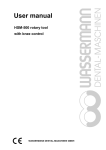
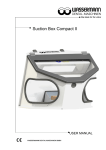
User manual
WW - 33
hydraulic press
(3 or 4 caps)
Figure 1: WW – 33 (1 – 3 caps)
WASSERMANN DENTAL-MASCHINEN GMBH
-1-
Dear customer,
Thank you for choosing a product from the Wassermann range. Wassermann
dental equipment incorporates the highest standards of quality and the latest
technology.
In order to enjoy maximum performance and years of trouble-free operation,
please read this instruction manual carefully before you connect this device and
start work, and operate the device according to the recommended guidelines. The
operation safety and the functionality of this device can only be guaranteed if you
follow both the general safety guidelines and the applying laws to prevent
accidents as well as the precautions given in this instruction manual. We are not
liable for any damages which occur due to inappropriate usage or faulty operation
of this device.
i
Make sure that anyone using this device has read and understood
this instruction manual.
Keep this instruction manual in a safe place where it can be referred to as
required at any time.
Company address:
Wassermann Dental-Maschinen GmbH
Rudorffweg 15-17
D-21031 Hamburg, Germany
Tel. : +49 (0)40 / 730 926 – 0 Fax.: +49 (0)40 / 730 37 24
E-mail: [email protected]
URL: http//www.wassermann-dental.com
Erstellt: 26.10.2007 / ms
Version: 1
Auftrag:
126999/091
//
126998/088
-2-
Contents
CONTENTS ........................................................................................... 2
1
FEATURES ..................................................................................... 3
2
FOR YOUR SAFETY ...................................................................... 3
YOUR USER MANUAL ..................................................................................................3
2.1
SAFETY GUIDELINES ........................................................................................4
RESPONSIBILITY FOR OPERATION AND DAMAGE.............................................................4
3
APPLICATIONS .............................................................................. 5
4
BEFORE YOU START.................................................................... 5
4.1 UNPACKING / TRANSPORT ....................................................................................5
4.2 SET-UP/STORAGE ................................................................................................5
5
START-UP....................................................................................... 6
6
OPERATION ................................................................................... 6
7
TROUBLESHOOTING / CORRECTING ERRORS ........................ 7
8 MAINTENANCE .......................................................................... 8
8.1 CLEANING ...........................................................................................................8
8.3 W ARRANTY .........................................................................................................9
8.4 SPARE PARTS AND ACCESSORIES ..........................................................................9
8.5 REPAIRS ...........................................................................................................10
9
TECHNICAL DATA ....................................................................... 10
126998 HYDRAULIC PRESS WW-33 FOR 2 - 4 CAPS ..................................................10
126999 HYDRAULIC PRESS WW-33 FOR 1 - 3 CAPS ..................................................11
10
EC CONFORMITY CERTIFICATE ............................................ 12
11
SPARE PART DIAGRAMFEHLER! TEXTMARKE NICHT DEFINIERT.
-3-
1 Features
The WW-33 hydraulic press, with continuous pressure up to 6 tonnes, presses
caps individually and appropriately for the material used. After ending one
pressing, it is immediately ready for further use as its solid plastic piston returns
automatically once the valve has been opened. A quality pressure gauge which
shows the pressure achieved with great accuracy, is recessed into the housing
and is thus protected from dirt. The WW-33’s oxidation-free piston (plastic), tensile
steel construction (no risk of breaking), and sturdy plastic-coated housing all
contribute to the unit’s long service life. As the distance between supports is 152
mm, the press is also suitable for larger caps (IVOCAP) and stirrup pieces.
SPECIAL DESIGN:
The WW-33 hydraulic press is also available with longer supports for 4 caps.
2 For your safety
Your user manual
Configuring and operating this equipment requires precise knowledge and
observance of the instructions in this user manual. The equipment is designed
only for its intended application.
Very important features are indicated as follows in this manual:
Warning!
This is a warning of risk situations and dangers. Failure to observe
!
this warning could be life-threatening. These warnings must be
observed.
Information!
i
This symbol draws your attention to specific features, which should
be noted.
-4-
2.1 Safety guidelines
• none
!
Responsibility for operation and damage
The responsibility for operating the unit lies exclusively with the owner or user if
the said unit is incorrectly serviced, maintained or altered by persons not
employed by an accredited dealer or if the unit is used in a manner contrary to its
specified purpose.
The unit must be maintained and operated in accordance with this user manual.
Wassermann Dental-Maschinen GmbH is not responsible for damage arising from
the non-observance of these instructions.
Guarantee and responsibility provisions contained in the sales and supply
conditions of Wassermann Dental-Maschinen GmbH are not extended by these
instructions.
i
Ensure that this user manual is accessible at all times and has
been read and understood.
-5-
3 Applications
With a continuous working pressure of up to 6 tonnes, the WW-33 hydraulic press
is used to press caps individually and in accordance with the material used.
Only use the device for this type of application.
4 Before you start
4.1 Unpacking / Transport
− Open the cartons, remove the packing materials, and carefully lift out the
instrument and accessories. Check that the accessories are correct (see 8.4).
− When transporting the unit, use appropriate packing materials to avoid
accidental damage.
4.2 Set-up/Storage
The press must be at room temperature before you use it.
i
− Set the unit up on a flat surface.
− Always ensure that the work area is sufficiently large (take the unit’s dimensions
into account). Do not set it up out of doors.
− If the unit is to be stored for an extended period, protect it from moisture and
dust.
− Before you start the press:
1. Take the pump lever out of the union piece.
2. Undo the bolt and remove the safety packing. Insert the lever and secure
it with the bolt.
3. Screw the ball on the end of the lever.
-6-
5 Start-up
− Centre the cap on the piston to guarantee even pressure distribution.
− Bring down the piston on the cap.
The usual pressure is between 2.5 and 5 tonnes. This is shown in
i
the green area on the pressure gauge. To avoid damage to the
cap and the press, do not pump beyond the zone on the pressure
gauge.
6 Operation
i
All instructions for using the unit, whether verbal, written or in the
form of practical guidance, are based on individual experience
and experimentation and can only be regarded as guidelines.
1. Prepare cap as per Point 5.
2. Turn the pressure valve (black knob on housing) to CLOSED.
3. Now increase pressure with the lever, staying within the permissible zone on
the pressure gauge.
4. If necessary, increase the pressure to the maximum.
5. Once the pressure remains steady, it can be released (valve opened).
6. Raise the piston and remove the cap.
-7-
i
The gauge will not be accurate while the pressure is being
distributed through the plastic. Full pressure can only be achieved
by pumping on the lever several times with appropriate pauses in
between. Once the cap is fully enclosed, the pressure remains
steady.
i
The return spring on the piston takes it back automatically to its
zero position. It has a stroke of about 12 mm. As soon as it
reaches this level, it is limited automatically. No more pressure is
possible.
i
The oil level should be monitored on the gauge when the piston is
down. If necessary, add hydraulic oil. A black vent screw is
provided for this purpose.
To remove (oil filler nozzle). This is located behind the left-hand
support at the top of the housing. No damage can result from
overfilling as the surplus oil merely flows out into the nozzle.
Note: Use only SHELL TELLUS 32 hydraulic oil.
7 Troubleshooting / Correcting errors
Fault
Little or no pressure
builds
Likely cause
Oil level below minimum
and air bubble has
entered system during
filling
Likely solution
Vent press as explained
below
Pressure drops to zero
despite enclosed cap or
piston rises under
pressure
Dirty pressure valve
Pump strongly with newly
filled oil (recommended oil)
-8-
GUIDELINES FOR VENTING:
1. Turn press on right side and pump.
2. Nothing? – then remove piston as described below and fill with oil up to top
edge of cylinder:
− Undo set screw in U-piece
− Pull lever forwards
− Pull piston up and out of cylinder
− Fill with oil (recommended oil)
− Re-install in reverse order, watching out for two points:
a) Do not tip the piston
b) Do not damage the square ring
i
If the above recommendations do not solve the problem, contact
your dental depot or our Service department.
8 Maintenance
8.1 Cleaning
The unit should be cleaned at regular intervals to ensure trouble-free operation.
Use normal cleaning products (sponge, soft cloth, mild detergent), but no chemical
additives.
The piston track should be cleaned daily with a clean linen cloth and then lightly
lubricated with the recommended hydraulic oil.
The model plate must always be legible and should not be removed.
-9-
8.2 Maintenance
Your Wassermann hydraulic press is maintenance-free. Just make sure that it is
kept clean.
8.3 Warranty
The warranty period for our instruments is 12 months. If faults occur within the
warranty period, contact your dental depot or get in touch directly with our Service
department.
Your hydraulic press should only be operated in perfect condition. If faults occur
which could harm operators or third parties, the unit should not be used until it has
been fixed.
This warranty does not cover damage caused by improper use, external
mechanical causes, transport damage or interference with the unit by
unauthorized persons.
8.4 Spare parts and accessories
Spare parts
Item number
125011
126023
291003
381001
392004
629004
629005
Description
Lever
Selector switch, compl.
Round ball DIN 319 - D25 x M6 black
Square ring, 6 x 1.5 for piston
Rubber foot D20 - H5, black
Hydraulic oil in 100 ml bottle
Hydraulic oil in 500 ml bottle
Accessories
Item number
126999
129990
129992
129993
129994
129995
129996
129997
Description
Steel press for 1 - 3 caps (not standard)
Universal cap (not standard)
Stainless steel clamp for 3 caps (not standard)
Stainless steel clamp for 2 caps (not standard)
Stainless steel clamp for 1 caps not standard)
Universal cap clamp for 3 caps (not standard)
Universal cap clamp for 2 caps not standard)
Universal cap clamp for 1 cap not standard)
- 10 -
8.5 Repairs
Servicing or repairs to the unit must only be carried out by trained technicians.
Only original spares are to be used. Responsibility for the product is voided if
altered by unauthorized persons or if inappropriate components are installed.
9 Technical data
126998 hydraulic press WW-33 for 2 - 4 caps
(SPECIAL DESIGN)
Working pressure:
Oil:
Piston:
Working range:
Overall dimensions:
Weight:
up to 6 tonnes
SHELL TELLUS 32 hydraulic oil
ø 95 mm (working surface)
Width 152 mm (distance between
supports)
Height - min. 102 mm
Height - max. 272 mm
(distance from piston to plate)
Width 200 mm
Depth 158 mm
Depth with lever 295 mm
16 kg
- 11 -
126999 hydraulic press WW-33 for 1 - 3 caps
Working pressure:
Oil:
Piston:
Working range:
Overall dimensions:
Weight
up to 6 tonnes
SHELL TELLUS 32 hydraulic oil
ø 95 mm (working surface)
Width 152 mm (distance between
supports)
Height - min. 42 mm
Height - max. 212 mm
(distance from piston to plate)
Width 200 mm
Depth 158 mm
Depth with lever 295 mm
14.7 kg
Noise emission ≤70 dB(A)
i
We reserve the right to make technical changes.
- 12 -
10 EC CONFORMITY CERTIFICATE
in accordance with 98/37/EG (Machinery guidelines)
Manufacturer:
Model:
Applicable
standards:
W A S S E R M A N N Product description:
Dental-Maschinen
GmbH
Rudorffweg 15 - 17
D-21031 Hamburg
WW-33 for 2 - 4 caps (special design)
WW-33 for 1 - 3 caps
Hydraulic press for
dental applications
(126998)
(126999)
DIN EN 61010-1:2004
DIN EN 60335-1:2007
Hiermit wird bestätigt, dass die oben bezeichnete Maschine den genannten EGRichtlinien entspricht. Diese Erklärung wird ungültig, falls die Maschine ohne
unsere Zustimmung verändert wird.
This is to confirm that the above mentioned machine complies with the described
EC rules. This declaration becomes invalid if the machine is modified without our
approval.
Cette machine est conforme aux normes en vigueur de la Communité Européene.
Cet avis est nul et non avenant si cette machine est modifiée sans notre accord.
Esta máquina, anteriormente mencionada, cumple con los limites requeridos por
el reglamento EC. Ahora bien, esta declaración quedará invalidada en caso de
realizar modificaciones al aparato sin nuestra aprobación.
Hiermee wordt bevestigd dat bovengenoemde machine voldoet aan de
voorgeschreven EU normen. Deze verklaring verliest geldigheid als er zonder
onze uitdrukkelijke toestemming wijzigen aan de machine worden aangebracht.
Place.date: Hamburg, 20.07.2007
Signed: ________________________
Wilfried Wassermann
(Managing Director)
Company stamp:
- 13 -
Notes:
- 14 -
Notes:
WASSERMANN Dental-Maschinen GmbH
Rudorffweg 15 – 17,
D-21031 Hamburg
Tel.: + 49 (0)40 / 730 926 – 0
Fax: +49 (0)40 / 730 37 24
e-mail: [email protected]
Internet: http://www.wassermann-dental.com