1
D
DLLPP PPrroojjeeccttoorr—
—U
Usseerr’’ss M
Maannuuaall
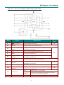
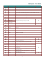
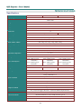
Rear view
ITEM
1.
LABEL
AC IN
2.
DESCRIPTION
Connect the POWER CABLE
(USB)
SEE PAGE:
11
For servicing purpose only
3.
COMPONENT IN
Connect a component video enabled device
4.
S-VIDEO IN
Connect the S-VIDEO CABLE from a video device
5.
VIDEO IN
Connect the COMPOSITE CABLE from a video device
6.
VGA OUT
Connect the RGB CABLE to a display
7.
VGA IN
Connect the RGB CABLE from a computer
8.
HDMI – 1
Connect the HDMI TM CABLE from a HDMI TM device
9.
HDMI – 2
Connect the HDMI TM CABLE from a HDMITM device
10.
DC 12V TRIGGER
Connect the 12V OUT
11.
Kensington Lock
Secure to permanent object with a Kensington® Lock
system
40
12.
Speaker
Outputs audio sound
10
13.
IR receiver
Receive IR signal from remote control
6
14.
AUDIO IN (L and R)
Connect the AUDIO CABLES from a audio device
15.
AUDIO IN
Connect an AUDIO CABLE from the input device
16.
RS-232C
Connect RS-232 serial port cable for remote control
17.
AUDIO OUT
Connect an AUDIO CABLE for audio loop through
18.
RJ – 45
Connect a LAN CABLE from Ethernet
10
10
Note:
If your video equipment has various input sources, it is recommended to connect in priority of
HDMI TM, component, S-Video, Composite for better picture quality.
–4–