1
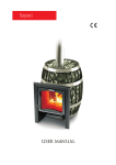
Battery Fire
USER MANUAL
TABLE OF CONTENTS
1. Application
2. Product line
3. Design features
4. Specifications
5. Stove structure
7. Marking and packaging
8. Proper use
9. Maintenance
10. Preventive maintenance
11. Warranty
12. Storage
13. Transportation
14. Disposal
15. Delivery package
1. APPLICATION.
«Battery-Fire» interior wood air heating stove is intended for efficient air heating of residential and
nonresidential premises with a temporary presence of people, as well as for cooking.
The stove operation is allowed within the range of ambient temperature changes from -60 to +40 ° C, climatic
factors value corresponds to version UKHL, placement category 3 according to GOST 15150-69.
2. PRODUCT LINE.
Product line is represented by 4 models: «Battery-Fire 5», «Battery-Fire 7», «Battery-Fire 9», «Battery-Fire 11»
with a nominal capacity of 6 to 16 kW to heat the space with a maximum capacity of 100 to 250 cubic meters
respectively (Table 1).
5, 7, 9, 11 numbers in stove models designation correspond to the number of slot convectors pairs the stove
equipped with, or the number of slot convectors visible on one side.
The same application, principle of operation and fuel type refer to all models of the stove. They differ in size,
weight, power, heated space capacity, a firebox size, the number of slot convectors, and the number of cast iron
burners.
All models have two versions: with an internal heat exchanger tank and without it. Heat exchanger tank is
intended to heat water for domestic use.
The stove version with an internal heat exchanger tank marked with the letter «WT» (tank) in its designation
as follows «Battery-Fire 7WT».
Table 1. «Battery-Fire» model line
«5»
«7»
100
150
200
250
6
10
13
16
Width
370
370
370
370
Depth
555
680
805
930
Height
760
760
760
760
42
52
60
72
Model
Heated area capacity max., cu. m.
Nominal power, kW
Overall dimensions, mm
Weight, kg
«9»
«11»
3. DESIGN FEATURES:
All «Battery-Fire» models have design features that distinguish them among the stoves of the class:
n
Stylish design allows the stove to be installed in any modern interior.
n
The cast iron burner with two rings of different diameter allows you to cook food on an open fire in pots
of different sizes, feed from the top and clean the stove upper part of soot.
n
The stainless steel heat exchanger tank (in versions with the letter «WT») allows you to heat water for
domestic use.
n
High performance slot convectors protect against hard infrared radiation and convert up to 77% of
useful heat into soft convective streams.
n
A capacious
firebox provides maximum amount of wood feeding for a long continuous burning.
n
A large
vertically-oriented firebox door allows you to top up the stove with wood easily.
n
Burning
intensity fine adjustment allows you to choose any mode of the stove operation steplessly.
n
A versatile
n
The flue
flue outlet allows you to install the flue stack both upward and backward with equal ease.
damper lock securely holds it in the chosen position.
n
A reasonable
in configuration firebox eliminates unburned fuel buildup, which gradually pours on the
grate under the influence of gravity
n
A removable
protection guards the firebox against burnout in hot coals clusters.
n
A sealed
lock ash drawer eliminates uncontrolled air flow, but at the same time you can remove ashes
with ease.
4. SPECIFICATIONS
Each model specifications are shown in Tables 2 – 5, and their dimensions are shown in Figures 1 – 8.
The fuel types permitted are wood, peat briquettes, sawdust briquettes for closed-type heaters, and pellets.
IMPORTANT! The maximum capacity of heated space defined by the conditions for effective convection
heat transfer and the walling overall heat-transfer resistance standards according to SNiP 23-02-2003
(construction norms and regulations), or according to the technical standards of the country in which the
stove is used.
Table 2. «Battery-Fire 5» and «Battery-Fire 5WT» specifications
Models
Heated space capacity, max. cu.m.
Nominal power, kW
Overall dimensions (WDH), mm
Weight, kg
Firebox door opening, mm
Combustion chamber capacity, l
Fuel maximum amount , l
Firewood length, max., mm
Flue diameter, mm
Flue recommended height, m
Heat exchanger tank capacity, l
555
405
«Battery-Fire 5WT»
100
6
370? 555? 760
44
150? 300
32
27
275
120
5
1,3
475
Figure 1. «Battery-Fire 5WT» overall
dimensions with a fuel stack installed upwards.
660
760
655
405
O120
555
370
250
760
655
370
O120
«Battery-Fire 5»
100
6
370? 555? 760
42
150? 300
35
30
295
120
5
-
475
Figure 2. «Battery-Fire 5WT» overall
dimensions with a fuel stack installed backwards.
Table 3. «Battery-Fire 7» and «Battery-Fire 7WT» specifications
680
530
680
530
760
655
370
250
655
760
O120
«Battery-Fire 7WT»
150
10
370? 680? 760
54
150? 300
45
40
400
120
5
1,3
660
370
«Battery-Fire 7»
150
10
370? 680? 760
52
150? 300
47
42
420
120
5
-
O120
Models
Heated space capacity, max. cu.m.
Nominal power, kW
Overall dimensions (WDH), mm
Weight, kg
Firebox door opening, mm
Combustion chamber capacity, l
Fuel maximum amount , l
Firewood length, max., mm
Flue diameter, mm
Flue recommended height, m
Heat exchanger tank capacity, l
600
600
Figure 3. «Battery-Fire 7WT» overall dimensions
with a fuel stack installed upwards.
Figure 4. «Battery-Fire 7WT» overall dimensions
with a fuel stack installed backwards.
Table 4. «Battery-Fire 9» and «Battery-Fire 9WT» specifications
725
Figure 5. «Battery-Fire 9WT» overall dimensions
with a fuel stack installed upwards.
«Battery-Fire 9WT»
200
13
370? 805? 760
63
150? 300
63
54
525
120
5
1,3
805
660
660
655
760
370
250
760
805
660
655
370
O120
«Battery-Fire 9»
200
13
370? 805? 760
60
150? 300
62
57
545
120
5
-
O120
Models
Heated space capacity, max. cu.m.
Nominal power, kW
Overall dimensions (WDH), mm
Weight, kg
Firebox door opening, mm
Combustion chamber capacity, l
Fuel maximum amount , l
Firewood length, max., mm
Flue diameter, mm
Flue recommended height, m
Heat exchanger tank capacity, l
725
Figure 6. «Battery-Fire 9WT» overall dimensions with a
fuel stack installed backwards.
Table 5. «Battery-Fire 11» and «Battery-Fire 11WT» specifications
930
780
850
Figure 7. «Battery-Fire 11WT» overall dimensions
with a fuel stack installed upwards.
930
780
660
760
«Battery-Fire 11WT»
250
16
370? 930? 760
75
150? 300
73
68
650
120
5
1,3
655
370
250
655
760
370
O120
«Battery-Fire 11»
250
16
370? 930? 760
72
150? 300
76
71
670
120
5
-
O120
Models
Heated space capacity, max. cu.m.
Nominal power, kW
Overall dimensions (WDH), mm
Weight, kg
Firebox door opening, mm
Combustion chamber capacity, l
Fuel maximum amount , l
Firewood length, max., mm
Flue diameter, mm
Flue recommended height, m
Heat exchanger tank capacity, l
850
Figure 8. «Battery-Fire 11WT» overall dimensions
with a fuel stack installed backwards.
5. STOVE STRUCTURE
All «Battery-Fire» models have the same structure. They differ only in the number of slot convectors and, as a
result in stove length. The main elements location is exemplified by "Battery-Fire7Á" in Figure 9.
The stove body has an originally shaped, fully welded design. The stove firebox (6) is made of structural steel, 3
mm thick.
The deflector (3) separates the firebox room from the fuel stack.
The convector slotted panels (11) on the stove sides shield hard infrared radiation from the stove and
accelerate the ambient air heating. Their original design allows "Battery-Fire" stove to be fitted in with any modern
interior.
In the version «WT» the heat exchanger tank (12) is installed at the rear of the firebox (inside) to heat water
for domestic use. Water heating system male connectors G3/4 extend through the rear convector.
High vertically oriented firebox door is opened at an angle of 120 ° that allows you to top up the stove with
wood easily.
The firebox door (4) has a cavity with a gasket mounted therein to press the door tightly to the stove body.
Locking mechanism securely locks the door in the closed position by turning the handle. On the door there is a
translucent wall made of heat resistant glass «SCHOTT ROBAX» (5).
When firing, primary air required for burning is supplied to the fuel through the ash drawer (8) door left ajar
and cast iron grate (13) to provide supplemental firing and a powerful high-temperature flame at the moment of
ignition.
ATTENTION! The stove is designed to operate only in smouldering conditions. Never use the stove in open
fire conditions (open flame is permitted only with firing; prolonged active burning conditions reduce the
stove service life).
For the further stove operation the air required for burning is supplied through the fine adjustment valve (7)
under the firebox door that allows you to choose any mode of the stove operation, from nominal to minimum,
steplessly.
1 – Cooking top
2 - Cast iron burner
3 - Deflector
4 - Firebox door
5 - Translucent wall
6 - Firebox
7 - Fine adjustment valve
8 – Ash drawer
9 - Flue damper lock
10 – Flue stack outlet
11 – Slot convector panel
12 – Heat exchanger tank
13 – Cast iron grate
14 – Support legs
15 – Firebox protection
15
Figure 9. «Battery-Fire 7WT» General view and the main elements location
Secondary air enters the firebox through the after burners.
The removable protection (15) with the grate (13) is installed at the bottom of
the firebox.
Reasonable in configuration the firebox bottom does not let unburned coals
collect. Ashes and slag gradually pour on the cast iron grate (13) under the influence
of gravity and through its slots fall into the ash box, with the help of which you can
clean the stove easily, without interrupting the combustion process.
There is a sealed ash drawer in «Battery-Fire» stoves. When passing to energysaving conditions it is pushed into the ashtray and «snaps» to the ledge (see. Figure
10). The seal on the drawer front wall let it full close.
Ashtray ledge
The upper body surface is used as a cooking top (1). There is a cast iron burner
Seal
(2) (which may be solid or the circle with a cover) on the cooking top to accelerate
cooking process.
Figure 10. Sealed ash drawer.
ATTENTION! Cooking top is heated to a high temperature
The stove external surface is coated with a heat-resistant organosilicon enamel of KO-868 type.
ATTENTION! The manufacturer reserves the right to change the stove design, without impairing its
consumer properties.
Fire gases are directed into the flue through the flue outlet of 120 mm diameter disposed at the rear of the
stove. There is a damper in the flue outlet to regulate flue draft.
«Battery-Fire» provides an opportunity to set the flue stack both backwards (Figure 11a) and upwards (see.
Figure 11.b).
à) flue stack set backwards
b) flue stack set upwards
Figure 11. Variants for flue stack installation.
6.MARKING AND PACKING OF THE STOVE
6.1. Marking
On a stove there is an information code plate with details about a model of a stove, its mass, factory serial
number, production date of a stove and other technical features, and also the information on certificates for this
model.
6.2. Packing
A stove is packed in a transport pack. Maintenance manual in a packaging bag and components are enclosed in
the stove combustor.
On a pack of a stove at the front part there is a label with information about a model of a stove, its mass, design
features and production date.
6.3 Procedure of remove the packaging by a consumer
1. Cut a packing tape
2. Remove cardboard boxes
3. Remove a polyethylene
4. Pull from a stove maintenance manual and components (if available) and take off a packing
5. Take away blocks and turn off fixing bolts
6. Remove advertising stickers from a surface of a protective film.
7. SUITABLE APPLICATION
7.1. Operational constraints
ATTENTION! Don't use the stove for industrial premises of categories A, B, V of fire and explosion safety in
accordance with NPB (ÍÏÁ) 105-95 (classification of premises and buildings of fire and explosion
safety).
ATTENTION! Don't use matters as fuel which aren't mentioned under point 4.
ATTENTION! Expressly prohibited using charcoal and coal briquettes as fuel.
ATTENTION! Don't use alcohol-containing means, benzene, kerosene and other highly inflammable
matters for ignition. Don't use a glossy paper, trimmings of wood particle boards, laminated flooring board,
orgalite because these matters would evolve noxious substances under burning, and would be cause of
outburst and damage of a stove.
ATTENTION! Don't use the stove with an empty heat exchange unit and a hot-water tank or an
unconnected system of water heating (if available).
ATTENTION! Don't use the stove inappropriately.
ATTENTION! Don't use the stove in autohouses, trailers and tents.
ATTENTION! Don't commit overheating of the stove at the time of its operation.
Overheating of the stove can be identified by red glow of the metal in the dark.
This situation can appear upon the uncontrolled air supply into the fire box. For example, when the door is
open. The stove warming up may lead to dangerous conditions of the stove operation and its premature breakdown.
7.2. Commissioning of the stove
ATTENTION! At the time of the first heating of the stove applied on the metal industrial oils and light
volatile compounds of organosilicone enamel evolve smoke and smell, which aren't evolved in the
following.
People having chest troubles and owners of the pets susceptible to smoke (for example birds) should take
precaution measures.
The first heating of the stove it is necessary making open-air with fire prevention discipline, at least one hour,
with charging of a fire box in half in the regime of active combustion.
For correct operation of the stove, at the time of the first heating it is necessary to organize a temporary flue
with height at least 2m.
For the model of stove with built-in heat exchange unit it is necessary to organize temporary water heating
system during the first pre-heating.
ATTENTION! Don't make mechanical action to a surface of a stove till complete cooling and final
polymerization of paint at the time of the first heating in order to avoid damage of a lacquer coating.
ATTENTION! To avoid the seal sticking to the stove body, the first firing should be performed with open ash
drawer.
Make sure that all elements of the stove are in safe conditions. Never use the faulty stove.
Fault free stove:
n
without visible body damages.
n
the door hinges freely, fits tightly to the body and securely locked.
n
there is a peripheral sealing cord in the door cavity.
n
the door glass without cracks, chips or other damage.
n
the firebox protection and grate without damage, burnouts and cracks.
n
the ash drawer moves freely and fits tightly to the body in the closed position.
n
the fine adjustment valve flap rotates freely and tightly covers the opening in the closed position.
n
the heat exchanger tank is sealed, without cracks or leaks.
Place the stove on a specially prepared place for its operation.
7.3. . Preparation of premises to installation of the stove
Protect from fire constructions of premises:
n
Walls (or partition) of inflammable materials have to be protected with plaster with thickness 25 mm on
an expanded metal or a metal plate on an asbestos paper with thickness 10 mm, from a floor to a level of
250 mm above the top of the stove.
n
A wall (or partition), through which fuel channel pass, shall be from nonflammable materials from a
floor to a level of 250 mm above the top of the stove. Recommended thickness of a wall is 125 mm.
n
A floor under the stove has to be protected by a foundation from brick at least two coating or other
nonflammable material at a distance of 380 mm from a wall of the stove.
n
A floor of inflammable and combustible with difficulty materials in front of a door of a combustor has to
be protected with a metal plate with size 700? 500 mm with length its side along the stove.
n
Make a fireproof partition in a passage of a flue through a ceiling.
n
At the time of installation of a flue in premises with a roof of inflammable materials a flue has to be
protected with a spark arrester of gauze with an opening with size no more 5? 5 mm, also have to block
with nonflammable roofing materials a space around a chimney.
ATTENTION! A place of installation the stove and chimney will be done in accordance with SNIP (ÑÍèÏ)
(construction norms and rules) 41-01-2003 or, in accordance with technical standards of a country,
where the stove would be exploited.
À
1
9
380
500
2
3
70
500
4
5
10
6
a metal plate on a heat-insulation material (an
asbestos paper with thickness 10 mm)
7
wood (inflammable material)
250
1200 min
À
380
8
700
a thermal insulation of a nonflammable material
(haydite/dross/ basalt wool)
bricks and so on (a nonflammable material)
1 - Bonnet
2 - Finish sandwich «Termofor»
3 – Flue module insulated (sandwich) «Termofor»
4 - Non-combustible ceiling
5 - Ceiling making
6 - Start-sandwich «Termofor»
7 - Walls of combustible material
8 – Stove base of fire-resistant material
9 – Pre-firebox sheet
10 - Metal sheet on asbestos board to protect the walls of
combustible materials
Figure 12: «Battery-Fire 7» installation in the room decorated with combustible materials (wood) on the base of
non-combustible material;
7.4. Stove assembly
ATTENTION! All the stove assembly and stones setting into the stones section works shall be carried out
only after total cooling off of the stove.
ATTENTION! The stove is heavy. Make sure that you have the possibilities and equipment for its moving.
ATTENTION! It is prohibited to install the stove in the places where the stove will create obstacles for
people moving during evacuation.
ATTENTION! It is necessary to carry out the installation of smoke sensors and gas detectors in the rooms
where the stove is installed.
Place the stove on a specially prepared place for its operation. Make sure that the stove is assembled and
installed properly.
If the installation instructions are not completely understood, or if you have doubts on whether the stove is
properly installed consult an experienced expert who knows all details concerning the procedure of the stove safe
and proper installation.
Installation drawings are shown in Figure 6. The distance from the firebox door to the opposite wall should be
not less than 1250 mm. The distance between the stove top and unprotected ceiling should be not less than 1200
mm.
The distance between the stove external surface, flue and wall should be at least:
n
for unprotected constructions of combustible and fire-resistant materials - 500 mm;
n
for constructions of non-combustible materials - 380 mm;
n
for constructions ? ? of combustible and fire-resistant materials protected in accordance with clause 7.2 -
380 mm;
Never install the stove in the corridor (passage), or about a flight of stairs, it may hamper passage in case of fire.
Do not install the stove in the bedroom. Do not place the stove in a recess in the wall (a niche), or in the fire place
(or in the stone stove).
7.5. Stove pipe assembly
During the use of the stove, the stove pipe shall be treated very carefully.
Stove pipe (chimney stack) – is the means of air ventilation of exhausted gases, it provides the draught that
facilitates the constant air intake into the heating equipment necessary for normal burning process. The stove is
designed only for operation with natural draught.
The stove shall have its own stove pipe.
ATTENTION! It is prohibited to connect the stove to any air ducts except for the cases when the air duct is
designed only for operation as the stove pipe.
ATTENTION! It is prohibited to connect the stove to the stove pipe that is connected to another equipment
or heating unit.
ATTENTION! The stove does not draw. The draught is made only with the stove pipe.
The stove pipe has two functions for the stove trouble-free operation. The first – is the piping of exhaust gases
generating during the fuel combustion. The second – is draught for air intake into the fire chamber for combustion
maintenance.
Draught – is the natural air or gases movement through the stove pipe. It generates due to the feature of warm
air to go upwards.
As far as the warm air moves in the stove pipe the low pressure is generated in the place of the stove
connection to the stove pipe. The greater pressure from the outside of the stove makes the air move into the area of
lower pressure – into the area of fire box. Thus the air intake into the fire chamber happens. This constant air inflow
is the draught.
The stove won't be operating effectively if there is no draught of the definite value.
The optimal draught for operation of stoves of «Termofor» trademark equals to 12±2 Pa.
Provided the excessive draught the considerable air flow will be entering the fire chamber and this will lead to
the stove overheating. Fire hazard may appear.
With the insufficient draught the insufficient amount of air for fuel proper and complete combustion will be
entering the fire chamber and this may lead to smoke generation in the room. The creosote generation increases
upon the formation of excessive smoke in the stove pipe and that may ignite creating the fire hazard in a house.
Creosote — is colourless (sometimes yellowish or yellow-green), inflammable, hardly soluble in water oily
liquid with strong smell and pungent taste extracted from wood and coal tar. This is the mixture of phenols mainly
guaiacol and cresols. Soluble in alcohol and ether. Poisonous.
Creosote will inevitably be generated in your stove and stove pipe. To reduce the speed of its generating it is
necessary to:
Use only dried billets that were dried during the period for not less than one year.
Use hardwood of broadleaf woods that is more compact (more heavy) and combust with the higher
temperature.
Before the use of the stove check and amend all that can influence the draught. Reducing or increasing of
draught may influence the draught by set of different factors, some of them may change in the course of time.
Factors influencing the draught:
Atmospheric pressure – may act from outside of a room, from inside and from both side by turns. Weather
conditions to which the high pressure conforms (clear and cold days) usually create the perfect conditions for
combustion.
Negative pressure outside the heated room – is created with the help of ventilation facilities such as:
Flue stack
Flue stack
«Termofor» cleanout
fitting with plug
Stack outlet
Stack outlet
b) Heat-resistant backward flue stack
À) Heat-resistant upward flue stack
Figure 13. A schematic sketch of stove connection to steel flue
ventilation inside the sauna room, draft hood, equipment for clothes drying, boilers with forced draught. Upon the
negative pressure the air flow in the stove pipe will go backwards at that «negative draught» or «backdraught» is
created.
Negative pressure can be neutralized by opening the door or window in the room with the stove.
The stove pipe temperature – the draught in the warmed up stove pipe is better than in the cold one. The cold
stove pipe quickly cools off hot gases going upwards and this will prevent their further going upwards. Combustion
of the first fuel charge will be enough for the stove pipe warming.
Stone stove pipes and stove pipes with section larger than the heating device are warmed up for a considerably
longer period of time.
The chimney stack shall have minimal number of elbows. The straight pipe is preferable. The use of more than
two piping may lead to the draught loss and possible smoke generation.
The manufacturer recommends the use of «Termofor» modular light-wall superalloy rust-resisting steel stacks
with diameter of 120 mm. They are effective, long-life and require minimal effort for installation and operation.
Steel stack installation with upward outlet is shown in Figure 13.a. When installing the stove with the stack
backward outlet, it is recommended that the stove should be connected to the flue through cleanout fitting with
plug (optional, figure 13.b). Backward stack outlet makes it convenient to connect the stove to the stationary flue
(Figure 14).
For reliable fastening of the units together it is necessary to use «collar-strainer»; the use of self-drilling screws
is allowed if necessary.
Stack outlet
Flue stack
Flue cleaning duct
Figure 14. A schematic sketch of stove connection to masonry flue
in the room decorated with non-combustible materials
In case of installation of thick-walled metal, ceramic, asbestos-cement or other chimney stack of greater weight
it is necessary to unload the stove from its weight.
ATTENTION! The manufacturer shall not be responsible for the influence of external factors on the
reduction of natural draught in the stove pipe.
ATTENTION! It is prohibited to use chimney stacks with galvanic coating.
ATTENTION! Do not use pipes from different manufacturers in the stove pipe.
ATTENTION! To avoid the smoke blowing into the heated room all the places of chimney stack units
connection against each other and the stove it is necessary to compact with high-temperature sealant (not
less than 1000°Ñ) providing the air-tightness of the pipe junctions.
ATTENTION! The junction of stove pipe units in overlaps and fire block is prohibited.
ATTENTION! The section of chimney stack located in the zone of sub-zero temperatures shall be obligatory
heat insulated by non-combustible material, withstanding temperatures not less than +400 °Ñ.
The ideal solution for chimney stack – is the installation of ready-made pipe units with heat insulation of
«sandwich» type of «Termofor» trademark.
In case of connection of the stove to fixed built-in stove pipe or in other cases it is not recommended to deflect
the axis of chimney stack from the vertical line for more than 45°.
ATTENTION! sauna stove and chimney stack assembly shall be carried out by qualified workers from the
specialized construction and installation company in compliance with the requirements of SNIP 41-012003 (construction norms and rules) or in compliance with technical norms of the country where the
stove will be used.
ATTENTION! It is strictly prohibited to make dismountable the connections of the stove with the stove pipe
or other structural elements of the room.
ATTENTION! In case of fire in the stove pipe shut the dampers of air supply into the fire chamber, leave the
room and immediately call the firemen.
In case of fire in the stove pipe it is necessary to have a clear scheme of actions that shall be elaborated by
consulting the specialist. After the fire in the stove pipe will die down, the stove pipe shall be cleaned and checked
for the destructions. Make sure that there are no flammables around the stove pipe.
7.6. Water heating system installation
The interior wood air heating stove «Battery-Fire» of «WT» version includes the heat exchanger tank to heat
water for domestic use
ATTENTION! Don't connect a heating system to a heat exchange unit.
The general scheme of water heating system installation is shown in Figure 15. The water heating components,
with the exception of an internal heat exchanger tank, are not supplied (optional).
A water heating system consists of:
n
A heat exchange unit (3) with two fitting adapter;
n
Connective pipes (pipeline) (7);
n
An outboard tank (5) for hot water with two fitting adapters for connecting to a heat transfer system and
one fitting adapter for installation of a tap of hot water distribution;
n
A tap for hot water (6), a tap for water drain from a system (8).
At the time of installation of a water heating system, a bottom of an outboard tank for hot water shall be over
of a level of a top fitting adapter of a heat transfer device no less than 30 cm.
min 50 ìì
4
5
1
6
7
2
3
min 30°
1 - Flue
2 - «Battery-Fire» stove
3 – Internal heat exchanger tank
4 - Venting
5 – External hot water tank
6 – Hot water distributing valve
7 – Communication pipes
8 – Water draining tap
8
Figure 15. General scheme of water heating system installation
ATTENTION! Water heating system installation should only be performed by qualified personnel from a
specialized construction organization.
ATTENTION! At the time of pipelines installation, don't permit its sagging in horizontal segments. It is
recommended to install these pipelines at an angle of up no less than 30°.
ATTENTION! Don't use pipes with work temperature of operation less than +95°C for a water heating
system.
ATTENTION! Don't use connecting elements of a pipe fitting with nominal width less than nominal width
of fitting adapter of a heat exchange unit.
ÂÍÈÌÀÍÈÅ! Çàïðåùàåòñÿ ýêñïëóàòèðîâàòü ñèñòåìó âîäîíàãðåâà ïîä èçáûòî÷íûì äàâëåíèåì,
îòëè÷íûì îò àòìîñôåðíîãî.
ATTENTION! Pressure test of the system by higher pressure shall be carried out when the heat exchange
unit is switched off.
ATTENTION! Only clear water shall be filled to a water heating system. It shall meet requirements of
quality in the context of salt, iron, lime content and other.
It is necessary to compact thread connections by plumbing sealant or PTFE-4 band GOST24222-80 (GOST –
national state standard).
7.7. Hot water tank assembly
ATTENTION! Hot water tank is the unit of extra high hazard that is why it is necessary to exercise caution
while being near it.
ATTENTION! «Termofor» company is not responsible for improper fastening of the tank.
ATTENTION! Avoid corrosive substances entering the hot water tank and water heating system.
ATTENTION! It is prohibited to pour water into the empty tank and (or) fill in empty water heating system
(if any) after stove starting up until the full cooling off of the stove and the tank.
An external hot water tank can be used with the stove «Battery-Fire».
The external tank is attached to the wall of a room in a user-friendly place and connected to the heat
exchanger tank with the piping (water heating system installation, see 7.6). The water in the tank is heated
circulating through the heat exchanger.
ATTENTION! To avoid injuries and burns it is necessary to provide maximum reliable fastening of the tank
to the wall.
ATTENTION! The wall at which the remote tank is installed shall support the weight of the tank fully filled
in with water.
When water starts to boil cold water shall be added into the tank. Don't pour the water in tank up to the top
because when water starts to boil it may spill over.
ATTENTION! It is prohibited to misuse the tank.
ATTENTION! It is prohibited to use defective tank having visual damages and (or) leakages.
ATTENTION! It is prohibited to use the tank under excessive pressure that differs from the atmospheric
one.
ATTENTION! It is prohibited to touch the warmed up to high temperatures surfaces of the tank with bare
hands or with other parts of body in order to avoid burns and damages.
«Termofor» company recommends to use «Battery-Fire» sauna stove along with tanks of «Termofor»
trademark.
7.8. Stove operation
ATTENTION! Before the stove firing up make sure that there is draft in the flue. Home draft testing is
performed as follows set a lighted match to the open firebox door, if the flame is pulled into the firebox
there is draft in the flue.
ATTENTION! Those who did not read the operating instructions must not use the stove in order to avoid
personal injury.
Check the firebox and ash drawer before every stove firing, and if necessary, clean them of ashes and other
items (unburnt firewood, foreign objects that were in wood (nails)) remaining since the previous use.
Firewood should be put through the door on the grate. When firing up put firewood loosely, pull out the ash
drawer, and open the damper flap to provide intense fuel firing and access of air to the combustion zone.
Do not top up the stove, it may cause a dangerous situation when opening the door. Do not leave the door
open after firing up.
ATTENTION! Do not place burning firewood close to the door. Failure to comply with this instruction may
result in door deformation, glass damage, and room smoke.
ATTENTION! Do not fire the stove with the door open. This can lead to dangerous stove operation
conditions, room smoke, and a fire accident.
ATTENTION! Forced air-feeding into the ash drawer is strictly forbidden.
To reduce the amount of harmful emissions you should first fire the upper portion of wood and during further
operation add firewood in small portions.
It takes some time a stable draft to arise after the stove firing up. Therefore, light smoke is possible if you open
the door when the stove operates in raising temperature conditions. The first fuel portion burning is enough for the
flue warming and draft effect to prevent smoke.
Later on the air supply, which affects the combustion intensity, can be controlled by opening or closing the ash
drawer and damper flap.
To put the next wood portion, fully open the damper flap and close the ash drawer, in a few seconds after that
gradually open the door.
While putting the next firewood portion, be careful not to put out the fire.
To terminate the stove operation, you should wait until the fuel is completely burned, then clean the stove of
ashes and close the door and the ash drawer.
ATTENTION! Do not extinguish with water.
ATTENTION! If the room temperature when intervals (version with a tank) is less than 5 ° C, then the
water must be completely drained from the water heating system.
ATTENTION! Do not operate the boiler with a defective flue.
ATTENTION! The use of wood with a moisture content of more than 20% results in smoke and soot
deposits rapid formation on the flue walls.
7.9. Characteristic faults and methods of elimination
Table 6.
Trouble type
Possible cause
Troubleshooting
Disturbance of a burning process
Chimney draft has deteriorated
Clean the chimney
Emergence of fuming
Chimney draft has deteriorated
Clean the chimney
Emergence of smell
Evaporation of remains of oils and
volatile components of enamel
Preheat the stove in accordance
with point 7.2. in a place of
installation with maximum
ventilation of a premise
Drops on an external surface of a
tube
Insufficient impermeability of
joints of chimney
Densify joints with heat-proof
sealant
Slow heating of a premise
Insufficient heat insulation of a
premise
Make warmer a premise
Incorrectly selected stove
Select a stove of higher power
Have used a fuel with high
burning temperature
Repair or replace the stove,
thereafter, use recommended fuel
Burnout of the fire bar and (or)
side walls
Overheating of the stove
7.10. Security measures at the time of the stove operation
Before the beginning of heating season the stove shall be tested. In the case of a fault, the stove shall be
repaired. A faulty stove is not permitted to operation. See signs of an efficient stove under point 7.2.
ATTENTION! Don't leave an unattended heating stove and, also, don't trust children and people, who are
in a state of drug, alcoholic or other toxic intoxication controlling the stove.
ATTENTION! Don't touch to heated till high temperature of surfaces of the stove with hand without
defense and other exposed parts of a body to avoid burns and injuries.
ATTENTION! Don't locate a chimney, other inflammable materials on the plate in front of the combustor
or nearer of 0,5 m to the surface of the stove.
ATTENTION! To avoid an accident contact with a heat surface of the stove it is recommended to make a
barrier in the form of a netting or a fender of nonflammable material which shalln't prevent air flow near
of the stove.
ATTENTION! Don't install a closed sheathing, which would prevent free convective stream.
ATTENTION! Don't dry any things and objects on a partly cold surface of the stove.
ATTENTION! Carbon monoxide generation may be deathful.
Carbon monoxide has neither smell nor colour, and is generated during the combustion of wood, coal, oil, gas
and other combustion agents. It is important to have good draught and reliable ventilation system so that
combustion products were exhausted through the stove pipe. Correctly installed stove designed so that to be
maximally safe during operation, nevertheless it is recommended to install the carbon monoxide sensors.
The sensors shall be installed at a distance from the stove to avoid false actuation. During the assembly and
service maintenance of smoke sensors it is necessary to follow the instruction provided by the manufacturer for
their assembly and location.
It is recommended to install the sensors at the level of «table» (but not close to the ceiling) to avoid false
actuation. Make sure that sensors actuate for the presence of carbon monoxide. In case of fire alarm (sensor
actuation):
n
Pay attention to the signs of poisoning with carbon monoxide: headache, sickness, sleepiness.
n
Increase the intensity of ventilation (open windows, doors)
n
Make sure that door and ash-drawer at the stove are shut tight
n
Check – if there is smoke from the stove (through the air dampers)
n
Check the connecting pipe and stove pipe for the presence of blowing, smoke obstacle, and back-draught.
n
Check carbon monoxide sensors for false actuation.
It is strictly prohibited to change the system of air supply into the fire chamber if you want to increase the
flame. The changes of air supply into the fire chamber differing from the designed one will create dangerous
conditions for the stove use.
ATTENTION! Place power lead and electrical equipment in the safety area described in the manual.
During the economical combustion takes place the intensive generation of tar and other organic fumes that
are mixing with exhausted steam and generated creosote. Creosote fumes condensate at relatively cold surfaces of
the stove pipe and may be accumulated there. And if afterwards they ignite this creates extreme temperatures in the
chimney stack and may lead to ignition of materials surrounding the pipe and cause fire.
ATTENTION! Provided the creosote ignition in the stove pipe shut all air dampers of the stove, leave the
room and call the firemen.
ATTENTION! The heating stove is a fire-hazard source.
Open and close the door only by the handle. Raked out ashes and drosses from the combustor shall be
extinguished with water and shall be located in a special fireproof place.
8. SERVICING
ATTENTION! Don't perform a mechanical cleaning and servicing of the stove till its full cooling.
8.1. Servicing of the stove and the chimney
Maintenance work of the stove and the chimney shall be regularly done for most efficient and safety operation
of the stove.
Sweep chimneys and stoves before the beginning of heating season and also during it in accordance with the
«Rules of fireproof routine in the Russian Federation» at least:
n
Once in three months for stoves;
n
Once in two months for continuous furnaces and fire-places;
n
Once in month for ovens and other stoves of continuous (long-term) heat.
It is necessary to use the stove, out of bounds of the Russian Federation, in accordance with technical standards
of a country, where the stove would be exploited.
Involvement of experts for checking and sweeping a chimney is preferable.
ATTENTION! The company «Termofor» doesn't have responsibility for consequences of unqualified work
to sweeping and checking of the chimney or the stove.
The chimney can be cleaned both mechanically (with special devices, such as bristle brushes, brushes, loads,
scrapers) and chemically (with the special chemical purifier «log-sweep»). A bristle brush would be selected
depending on a form and a cross-sectional size of a tube.
ATTENTION! Take necessary measures to protect eyes and anatomical airways from a dust and soot at the
time of a mechanical cleaning of chimneys.
ATTENTION! Read instruction through carefully and follow recommendation of a manufacturer of
chemical purifiers. Not recommend using compositions for carbon burning-off are self-made.
ATTENTION! To avoid gas ducts clogging while cleaning the flue, you must disconnect the stove.
8.2. Service maintenance of door translucent screen
To prevent soot accumulation at the translucent screen (glass) it is necessary to clean it from time to time.
Accumulation of acidulous thin coating (of soot) will as the result erode and weaken the glass of the
translucent screen.
It is important to obey the following instructions so that the glass can be used for a long period of time.
On the regular basis inspect the glass for chips and cracks. Provided any cracks or chips are found immediately
put out the stove and address the manufacture for glass replacement issue.
Don't slam the door; don't otherwise hit the glass. When shutting the door make sure that billets and other
objects do not stick out from the fire chamber so that not to damage the glass.
Don't start up fire near the glass or in such a manner that during the burning process it may be close to the
glass.
When cleaning the glass do not use materials that can scratch or in other way damage the glass. Scratches on
the glass may during the use lead to glass destruction.
Never try to clean the glass while it is still hot. Before kindling the glass shall be completely dry.
Never put into the stove materials that can ignite explosively. Even small explosion in the closed space is
capable to smash out the glass.
Glass cleaning from sooty deposits shall be carried out as and when necessary by soft cloth wetted with special
solution for fireplace and stove glasses in accordance with the instruction.
It is prohibited to use the stove with damaged translucent screen. In case of glass damages for its replacement it
is necessary to install only high-temperature ceramic glass with thickness of 4 mm and correct dimensions. For
correct replacement order see cl. 9.
Do not use instead of the glass the heat-strengthened glass or thickened window glass. Contact the
manufacturer for the glass replacement issue.
9. PREVENTIVE MAITENANCE
The firebox protection with the grate in it and heat exchanger tank are exposed to the highest temperature, so
the metal they are made of may deform or burnout during the operation time. Should this happen, the damaged
parts must be replaced. Such damage occurs due to improper use of the stove and is not covered by warranty.
To replace a damaged protection you should:
1. Remove the damaged protection from the stove by bending the metal clamps on the firebox sides;
2. Set a new protection in the stove. The firebox protection must be set in the lower part of the firebox and
the grate placed closer to the rear wall. The grate is set in a seat in the protection turned with its flat side
to the firebox.
To replace the heat exchanger tank, first, loosen the nuts on the
connections on the exterior side of a rear convector (see. Figure 16) and
take out the heat exchanger tank from the stove through the door. Put
spacer sleeves on the connection between the firebox wall and the
convector to prevent convector damage while tightening the nut. Noncombustible gasket, which is placed on the connection, should be placed
on the inside of the firebox.
In operation, the sealing cord in the stove door and the ash drawer
gasket wear out, that reduces the tightness when closing. The manufacturer recommends that you should periodically replace them. This damage
(wear and tear) is not covered by warranty.
Sleeve
Nut
Connection
Convector
Non-combustible
gasket
Heat exchanger tank
Figure 16. Heat exchanger removal
Top
Self-drilling screw
Glass
Frame
Glass
Sealing cord
Sealing cord
Figure 17. «Battery-Fire» stove door
Bottom
Figure18. «Battery-Fire» door glass
In case of door translucent wall (glass) damage you should replace it (see. Figure 15):
1. Remove the 6 screws securing the frame (Figure 17).
2. Remove the frame with the glass remnants. Be careful, glass pieces may fall and cause personal injury.
3. Set the new glass with attached tape into the frame. The tape on the glass must be attached as shown in
Figure 18.
4. Secure the frame with glass to the door with screws.
Paint coating damage during operation may cause corrosion, which is not covered by warranty. To avoid this,
the manufacturer recommends that you should touch-up the body with heat-resistant organosilicone enamel with
heat resistance of at least 600 ° C.
10. WARRANTY
Warranty period for the product is 12 months from the date of transfer it to the Consumer.
If the Consumer finds an inadequacy in the stated specifications (features) of the Products, the Consumer will
have the right to address his Claim to the organization (the Client) which has sold these Products.
Herewith, the Client has right to address to the Manufacturer that settle the Claim.
If an identified misstatement is satisfied the following conditions, the Manufacturer will make reworking the
Products integrally or its unit (in accordance with decision of the Manufacturer), substituting a damaged unit or its
elements, free of charge or compensating for damage by other means (with the approval of the Consumer):
1) It has established that a defect is in 12 months from the date of transfer the Products to the Consumer;
2) It has established that a defect is due to the fault of the company «Termofor».
Warranty doesn't apply to the Products and also its units or elements which have been changed by the
Consumer. Warranty doesn't apply to elements of the Products which shall be substituted at the time of normal
operation.
The Manufacturer doesn't give warranty to the products if the Consumer wouldn't fulfill the requirements of
the Maintenance manual.
If the Consumer (a person who has installed the product) wouldn't follow the technical requirements of
products installation and operation it leads to release of the Manufacturer from liability.
Warranties are ended from the time of determine of conditions stated above and in the future will not be
renewed.
11. STORING
The product shall be kept in the pack in accordance with GOST (ÃÎÑÒ) 15150-69, group 3 (enclosed premises
with a free ventilation without artificially adjustable climate conditions) at a temperature from -60 till +40?C and
relative air humidity no more than 80% (at a temperature of +25?C).
In air of a premise of storing the product shalln't be aggressive substances (acid fumes, alkalies).
Storage requirements concern to storehouses of the Consigner and the Consumer.
An expiration date of the product in a consumption package without reconservation is no more than 12
month.
12. CARRIAGE
12.1 Conditions of carriage
Carriage of the product is permitted in a transport packaging by all types of transport (including heated
airproof compartments of aircrafts no limits distance).The kind of carriage shall be small and low-rise at the time of
waggonage.
At the time of carriage of the product it shall be provided for defense from intrusion of dust and rainfall.
Canting of the product is not allowed.
12.2 Preparation for carriage
The products shall be fastened for guarantee of steady position and excluding mutual displacement and strokes
before carriage.
The requirements of handling instructions on the package shall be strictly observed at the time of load
handling.
13. UTILIZATION
The stove and its elements shall be dismantled and sent to utilization at the time of end of operating life or
breakdown of the stove (in consequence of improper operation).
At the time of disconnect the stove and its elements from the flue shall protect eyes and anatomical airways
from a dust and soot in the elements of the system which have arisen during the operation.
ATTENTION! Dismantle the stove only after its full cooling.
The product does not contain in its composition dangerous or toxicant substance which would cause harm
human health or environments. At the time of end of operating life, the stove is not danger for life, human health
and environments. As a result of this, the product can be utilized in accordance with the rules of utilization of
common industrial waste.
14. DELIVERY PACKAGE
The set of delivery for all "Battery-Fire" models includes:
Heating and cooking stove assembly
Cast iron burner (set)
Fuel outlet duct
Ash drawer
Operating instructions
Packing
EC distributorship and stock
Certus ltd, Unijas str. 6, Riga, Latvia
t. + 371 67516914
www.certus.lv
1 pc.
1 pc.
1 pc.
1 pc.
1 pc.
1 pc.