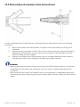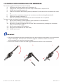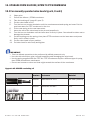
1
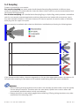
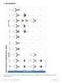
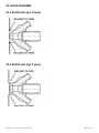
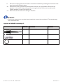
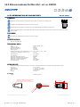
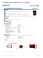
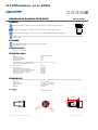
W9™ SAMPLING VALVE User Manual D O N ’ T G A M B L E W I T H Y O U R S A M P L E ™ DOCUMENT VERSION LOG The table below lists previous versions of this User Manual and states the major changes between versions. This version list is introduced in November 2015. Version # Version date Major changes from previous versions 1 September 2015 Latest version without version log th 2 11 November 2015 Various amendments to the text in 5, 5.1, 5.2, 6.3, 6.4, A new chapter 6.7 Flow. Added Warning in 13.2. New chapter 13.3. New illustration in 14. Updated data sheets in 16.x. INTRODUCTION: MANUFACTURER: Keofitt A/S Kullinggade 31 5700 Svendborg, Denmark TYPE: W9™ SAMPLING VALVE PATENTS: U.S. PAT. 5,246,204 • E.P. 0468957 YEAR OF INTRODUCTION:1998 YEAR OF REVISED DESIGN:2014 MANUAL LAST UPDATED: Nov. 2015 The English version of this Manual is the governing version and it is the only authorized version. Consequently, KEOFITT cannot be held liable for other versions including translations of this Manual. CONTENTS 1. PRESENTATION.............................................................................................................................. 7 1.1 Definition of terms.............................................................................................................................7 1.2 Quick start.........................................................................................................................................9 2. CLEANING – DISINFECTION – STERILISATION ..........................................................................10 2.1 Clean-In-Place (CIP)........................................................................................................................ 10 2.2 Disinfection.................................................................................................................................... 10 2.3 Sterilisation.................................................................................................................................... 11 3. VALVE FUNCTION.........................................................................................................................12 4. EVERYDAY USE OF THE VALVE....................................................................................................14 4.1 Pre-production treatment.............................................................................................................. 14 4.2 Chemical cleaning, CIP.................................................................................................................. 14 4.3 Chemical Disinfection.................................................................................................................... 14 4.4 Steam sterilisation......................................................................................................................... 14 5. VALVE OPERATIONS....................................................................................................................15 5.1 Chemical CIP.................................................................................................................................. 15 5.2 Chemical disinfection.................................................................................................................... 16 5.3 Steam sterilisation......................................................................................................................... 18 5.4 Sampling......................................................................................................................................... 20 6. TECHNICAL DATA..........................................................................................................................21 6.1 Material............................................................................................................................................ 21 6.2 Certificate........................................................................................................................................ 21 6.3 Pressure (max.)............................................................................................................................... 21 6.4 Temperature (max.)......................................................................................................................... 21 6.5 Surface finish.................................................................................................................................. 21 6.6 Viscosity:.......................................................................................................................................... 21 6.7 Flow................................................................................................................................................. 22 7. VALVE BODIES..............................................................................................................................23 8. VALVE HEADS...............................................................................................................................24 9. PARTS & ACCESSORIES...............................................................................................................25 10.MOUNTING INSTRUCTIONS.........................................................................................................26 10.1 Location......................................................................................................................................... 26 10.2 Before welding.............................................................................................................................. 26 11. WELDING INSTRUCTIONS..........................................................................................................27 11.1 Welding method............................................................................................................................ 27 11.2 Guideline welding values............................................................................................................. 27 12. BLOCK DIAGRAMS.....................................................................................................................28 12.1 Keofitt valve type T (tank)............................................................................................................. 28 12.2 Keofitt valve type P (pipe)............................................................................................................ 28 12.3 Keofitt valve type P (pipe connection vertical) Inline................................................................. 29 12.4 Keofitt valve type clamp connection........................................................................................... 29 12.5 Keofitt valve type Varivent®......................................................................................................... 30 12.6 Keofitt valve type thread.............................................................................................................. 30 13. MAINTENANCE............................................................................................................................31 13.1 Spare parts list.............................................................................................................................. 31 13.2 Disassembly and assembly of valve body and head.................................................................. 32 13.3 Disassembly of valve head.......................................................................................................... 33 14. INSTRUCTIONS ON REPLACING PTFE MEMBRANE ..................................................................34 15. UPGRADE FROM SILICONE/EPDM TO PTFE MEMBRANE.........................................................35 15.1 For manually operated valve heads type H, K and Q ................................................................ 35 15.2 For manually operated valve heads type B ................................................................................ 36 15.3 For pneumatically operated valve heads type N........................................................................ 36 16. MEMBRANES..............................................................................................................................38 16.1 Silicone membrane - art. no. 600051......................................................................................... 38 16.2 Silicone membrane for Micro Port - art. no. 600251................................................................. 39 16.3 EPDM membrane - art. no. 600052........................................................................................... 40 16.4 EPDM membrane for Micro Port - art. no. 600252.................................................................... 41 16.5 FFKM membrane - art. no. 600053............................................................................................ 42 16.6 PTFE membrane - art. no. 850055............................................................................................. 43 1. PRESENTATION The Keofitt W9™ sampling valve can be readily cleaned and disinfected/sterilised as it meets both hygienic and process design requirements. Effective cleaning and disinfection/sterilisation of the sampling valve can be carried out between random samples independently of the course of the production process without compromising the same. The coaxial design and the electro polished valve interior ensure absolute cleanability. The W9™ valve is 3-A authorised and EHEDG Type EL Class I certified. The American 3-A Sanitary Standard is normative for the component’s ease of cleaning and sterilisation and ensures optimum conditions for food products, which comes in contact with the component in question. The European EHEDG Type EL certificate is issued based on the cleanability of the valve and the test method is an indicator of good inherent hygienic equipment design. Keofitt valves are used in a wide range of processing industries, such as breweries, dairies, juice/soft drinks and the biotechnological and pharmaceutical industries. 1.1 Definition of terms In order to ease the reading of this manual and to avoid any misunderstanding, please refer to the definition of terms in the table below: TERM DEFINITION 3-A Sanitary Standard 3-A SSI is an independent, not-for-profit US corporation dedicated to advancing hygienic equipment design for the food, beverage and pharmaceutical industries. An acid is a chemical substance whose aqueous solutions are characterized by a sour taste and the ability to react with bases and certain metals (like calcium) to form salts. Aqueous solutions of acids have a pH of less than 7. A lower pH means a higher acidity, and thus a higher concentration of positive hydrogen ions in the solution. Removes limestone and most mineral deposits. Alkalis are all bases, which form hydroxide ions (OH-) when dissolved in water. The terms “base” and “alkali” are often used interchangeably. Alkalis have a pH value above 7. Alkalis dissolves fat and oil, destroys protein and attacks light metal. The process of withdrawing a sample from the production equipment through a closed circuit, which has been sterilised and kept sterile with no exposure to the ambient during the sampling process. See Microbial load. See Microbial load. A few disinfectants will kill spores with prolonged exposure times (3–12 hours); these are called chemical sterilants. Chlorine is a chemical element with symbol Cl and atomic number 17. It belongs to the halogen group together with for instance iodine. It is a strong oxidizing agent and reacts with many substances. These properties make chlorine compounds efficient disinfectants. Abbreviation of Clean-In-Place. The process of cleaning a process component (like a sampling valve) without removing it from the production line. Removal, usually with detergent and water or enzyme cleaner and water, of adherent visible soil on a surface. Acids Alkali Aseptic sampling Bioload Bioburden Chemical Sterilant Chlorine CIP Cleaning KEOFITT USER MANUAL PAGE 7 Complexing agent Contact time Enzymes Disinfectant Disinfection Detergent EHEDG Electro polishing Exposure time Flow path Germicidal Microbial load Microorganisms Peracetic acid Process media Representative sample Sanitization SIP A substance capable of forming a complex compound with another material in solution. Improves the cleaning properties of a detergent. The time span during which the item is in contact with the detergent or the disinfectant. Molecules, which are added to cleaning agents to ease the removal of specific organic material. Assures same cleaning effect at a lower temperature. Usually a chemical agent that destroys harmful microorganisms but might not kill bacterial spores. Thermal or chemical destruction of microorganisms. Disinfection is less lethal than sterilisation, because it destroys most recognised microorganisms but not necessarily all microbial forms (e.g. bacterial spores). A cleaning agent that has no antimicrobial effect, but in diluted solutions good cleaning properties. Abbreviation for the European Hygiene Engineering and Design Group. EHEDG is a consortium of equipment manufacturers, food industries, research institutes as well as public health authorities promoting safe food by improving hygienic engineering and design in all aspects of food manufacture. Electro polishing is an electrochemical process by which the high points within the microscopic surface texture are removed and the corners rounded. This results in Reduced Product Adhesion, Ease of Cleaning and Improved Corrosion Resistance. Period in a sterilisation/disinfection process during which the item is exposed to the sterilant/disinfectant at the specific sterilisation/disinfection parameters. The path the sample flows from the tank or process equipment to the sample recipient. The property of an agent to destroy microorganisms. The number and types of viable microorganisms with which an item is contaminated; also called bioload or bioburden. Animals or plants of microscopic size. As used in food and pharmaceutical industries, generally refers to bacteria, fungi, viruses and bacterial spores. A commonly used disinfectant, which is efficient at low temperature and short contact time. Relatively harmless as it decomposes into carbon dioxide (CO2) and water (H2O). The product in the process equipment and the product from which a sample is taken. A sample which when it reaches the laboratory is still identical to the process media. A sample which is in no way contaminated or altered during neither the sampling process nor the transport to the laboratory. The application of a chemical agent that reduces the number of bacterial contaminants to a safe level as judged by the public health authorities. The official sanitizer protocol indicates that 99.999% of the specific test bacteria be killed in 30 seconds under the conditions of the test. Abbreviation for Sterilise-In-Place. The process of rendering a process component (like a sampling valve) sterile without removing it from the production line. KEOFITT USER MANUAL PAGE 8 Spores Relatively water-poor resting cells surrounded by an impervious cell wall, which makes them relatively resistant to disinfectants and sterilants. They are dangerous as they can survive in adverse conditions and re-emerge as live bacteria at a later stage. The property of an agent that kills spores. The process of using saturated steam under pressure as the sterilising agent. State of being free from all living microorganisms. In practice, usually described as a probability function, e.g., as the probability of any microorganism surviving sterilisation being one in one million. A few disinfectants will kill spores with prolonged exposure times (3–12 hours); these are called chemical sterilants. Validated process used to render an item free of all forms of viable microorganisms. In a sterilisation process, the presence of microorganisms is expressed in terms of probability. Although this probability can be reduced to a very low number, it can never be reduced to zero. The probability of a viable microorganism being present on an item after sterilisation. Usually expressed as 10–n; a SAL of 10-6 means <1/1 million chance that a single viable microorganism is present on a sterilised item. A tenside is a surfactant that reduces the surface tension of water and assures a faster and better contact between the detergent and the soil. Sporicidal Steaming Sterile Sterilant Sterilisation Sterility Assurance Level Tensides 1.2 Quick start Cleaning Disinfection Sterilisation KEOFITT USER MANUAL 5.4 Sampling 5.3 Steam sterilisation 5.2 Chemical disinfection 5.1 Chemical CIP 4.4 Steaming 4.3 Chemical disinfection 4.2 Chemical cleaning CIP Required hygienic level 4.1 Preproduction treatment The table below gives you an overview of the relevant chapters to read depending on the operations you want to perform to obtain the required hygienic level. PAGE 9 2. CLEANING – DISINFECTION – STERILISATION 2.1 Clean-In-Place (CIP) Thorough cleaning of the valve is a prerequisite for proper disinfection or sterilisation. Cleaning of the valve is the removal of any visible residual product, it be organic or inorganic. It may be done using either steam (continuous steam will eventually lead to sterility; SIP = Sterilise-In-Place) or a suitable liquid detergent. Cleaning is the removal of adhering soil from the environment and from the previous sample (to the extent it has not been removed by the recommended post-sample cleaning). Cleaning is usually performed by flushing with water followed by a thorough washing with an appropriate detergent and finished off with a thorough rinsing with water. Depending on the actual process media the proper detergent must be determined in cooperation with your usual supplier of detergents. The company Novadan ApS, Kolding, Denmark - www.novadan.dk, has supplied the generic table below for your convenience. What to clean for Generic cleaning agents Comments Fat Alkali and Tensides Protein Alkali, Acids, Tensides and Chlorine Sugar, Salt Water is usually sufficient as the product is water soluble Minerals Biofilm Acids, Complexing agent Alkali and Chlorine, Peracetic acid, possibly Enzymes Heat will facilitate the cleaning process as the fat melts Coagulation and burning when heated, which makes the product hard to remove. Sugar caramelises when heated, turning into a hard sticky substance, which is difficult to remove Often seen as lime scale Biofilm is an accumulated mass of microorganisms that is tightly adhered to a surface and cannot be easily removed. Starch Alkali and Chlorine 2.2 Disinfection Although CIP removes all visible residues of the process media the valve surfaces will still be contaminated on a microscopic level. Depending on your actual process media it will be necessary to carry out a disinfection operation in order to a) reduce the microbial load to an acceptable level (also referred to as Sanitization) or b) destroy critical microorganisms, but not necessarily all microbial forms (e.g. bacterial spores). The disinfection process may be carried out in one of two ways and to different levels of disinfection depending on a) the initial microbial load distribution, b) the required hygienic level and c) the type, exposure time and concentration of the chemicals used (if using a chemical disinfectant): • By steaming (in a continued process after steam cleaning) • By applying one or more suitable liquid chemical disinfectants There are a number of chemical disinfectants. It is important to choose the right one, the right concentration and contact time and the right method for your current application. Your usual supplier of chemical disinfectants can support you in choosing the right disinfectant for your process media and the specific group of microorganisms you are aiming at. The company Novadan ApS, Kolding, Denmark has supplied the table below, as a preliminary indication of which type of disinfectant to use: KEOFITT USER MANUAL PAGE 10 Halogenes (Clorine) Disinfectant Microbes to inactivate Peroxides (hydrogenperoxid & peracetic acid) Alcohol (70%) Gram-neg bacteria Salmonella Campylobacter E. Coli and others... Gram-pos bacteria Listeria Bacillus cereus Clostridium and others... Bacteria spores Bacillus cereus and others... Bacteriophage Yeast Fungi Virus Legend: Efficient Limited effect Little/No effect NOTE! The final choice of detergent, disinfectant and method lies with the user, supported by the supplier of the CIP fluids and disinfectants, as it is very much dependant on individual concerns and circumstances. 2.3 Sterilisation Sterilisation is a high-level disinfection designed to render the valve free of all forms of viable microorganisms (incl. bacterial spores) to a high level of certainty; the so-called Sterility Assurance Level or SAL. A SAL value of 10-6 means that the probability (or risk) of a single viable microorganism being present on the valve interior afterwards is only 1 in 1,000,000 which is a generally accepted level for calling an item sterile. Although the probability can be reduced to a very low number, it can never be reduced to zero. Sterility may in practise only be obtained by steaming. Disinfectants exist that in high concentrations and for a prolonged exposure time will be able to inactivate all forms of microorganisms and render the valve interior sterile with a high probability; these disinfectants are called chemical sterilants. However, the application of chemical sterilants is most often problematic due to a) a required high concentration, which causes an operator hazard and b) the several hours of exposure time. NOTE! Furthermore, sterilisation with a chemical sterilant may not convey the same sterility assurance as sterilisation with steam, because the germicidal and sporicidal kinetics are much less investigated and documented for chemical sterilants compared to steam. KEOFITT USER MANUAL PAGE 11 3. VALVE FUNCTION The valve is designed to regularly take representative samples in the production process. The valve is therefore designed such that effective cleaning, disinfection/sterilisation and sampling can be carried out regularly without interrupting the production process. NOTE! The membrane functions as a dynamic seal in the valve seat as well as a hygienic static sealing against the valve head. Chemical The table below describes the two fundamentally different ways of preparing the valve for sampling, 1) Chemical cleaning/disinfection and 2) Steaming: Method Description Chemical cleaning Liquid detergents are used to clean the This process is adopted where steam valve. is not available or where the product CIP = Clean-In-Place cannot withstand the exposure to heat. Involves several stages with flushing, cleaning and rinsing between batches. It adds 2 more stages to the CIP: A disinfection process using an appropriate chemical liquid disinfectant application of disinfectant and final rinse. usually follows the cleaning process. Involves handling of potentially The valve interior is wetted, soaked or flushed with an appropriate hazardous chemicals. disinfectant. Steam is supplied for 1 minute just Steaming does flushing, cleaning, before and immediately after sampling. rinsing and sterilisation in one operation. Steaming is not suitable with heat sensitive products. Steaming entails the risk of burns. Chemical disinfection Thermal Sterilisation Pros & Cons Flushing with water followed by the supply of a chemical detergent through the upper of the valve’s two hose pieces results in cleaning the valve (CIP). It is the perfect, hygienic design and surface finish of the inner part of the valve, which enables easy, efficient and reliable cleaning in a closed state of the valve. Supplying steam through the upper of the valve’s two hose pieces results in cleaning and sterilisation. It is the perfect, hygienic design and surface finish of the inner part of the valve, which enables sterilisation in a closed state. According to an EHEDG based test conducted by the Biotechnological Institute in Denmark, the valve is sterile after just 1 minute’s supply of steam at a pressure of 1 bar(g), 121 ºC. Steaming is therefore a SIP process (Sterilise-In-Place). Following CIP or SIP, but prior to sampling, a sterile plug of rubber or stainless steel is fitted to the top hose piece. When the valve is opened the process product will run out of the lower hose piece. WARNING • During sterilisation with steam the valve will become hot and care should thus be taken when operating the valve • The valve is designed for use in working conditions of up to 6 bar(g) pressure and temperatures of up to 121 C. It is therefore important to be aware that the rubber plug (designed for max. 3 bar(g)) or the steel plug (designed for max. 10 bar(g)) may be forced out at high speed, if not seated properly • When steaming always use dry saturated steam without condensation at max. 1 bar(g). At KEOFITT USER MANUAL PAGE 12 higher pressure the membrane may be damaged/split • Always remember to use safety goggles when steaming, CIPping, taking samples and all other operations of the sampling valve IMPORTANT • The valve cannot be used for vacuum since the membrane will be sucked hard into the seat and the valve will not function properly • The membrane is available in 3 different qualities: Silicone, EPDM and PTFE • The Silicone membrane has the advantage that it in general can withstand high temperatures, but it cannot tolerate moisture condensation resulting from steam sterilisation • The EPDM membrane is better able to cope with the condensation in the steam and at the same time it can be used with a majority of CIP fluids and disinfectants in normal concentrations • The PTFE membrane resists all CIP fluids and disinfectants except highly oxidising acids in high concentrations KEOFITT USER MANUAL PAGE 13 4. EVERYDAY USE OF THE VALVE This chapter gives an introduction to how the sampling valve works in different operating conditions. For specific operator instructions please refer to the chapter “VALVE OPERATIONS”. 4.1 Pre-production treatment Before every new production batch the sampling valve is cleaned and disinfected/sterilised together with the tank or vessel or the entire production line. Make sure the valve is in its open position during the initial line CIP to allow cleaning of the valve seat and the membrane contact surface. Also allow CIP fluid, disinfectant or steam to flow through the inlet and outlet hose pieces. Remember to close the valve after the final rinse and prior to starting up the next production batch. 4.2 Chemical cleaning, CIP During production and prior to sampling, cleaning takes place with the valve closed and involves the following stages: 1.Pre-rinse Flushing with water to mechanically remove product residues 2.Clean Applying a detergent to remove remaining visible product residues 3. Final rinse Rinse with clean water to remove all traces of detergents Usually this procedure is followed by disinfection (see below), but for some application CIP might be sufficient. It depends on your (microbiological) requirements, the detergents applied and the process media to clean for. Consult your supplier of CIP fluids. In some cases where the process media is for instance water, CIP might not even be necessary and you may go directly to disinfection. 4.3 Chemical Disinfection Disinfection takes place with the valve closed and involves the following stages of which the first 3 are identical to CIP: 1.Pre-rinse Flushing with water to mechanically remove product residues 2.Clean Applying a detergent to remove remaining visible product residues 3. Intermediate rinse Rinse with clean water to remove all traces of detergents 4.Disinfection Apply an appropriate disinfectant targeting one or more or all microorganisms 5. Final rinse Rinse with cleaned water to remove all traces of the disinfectant 4.4 Steam sterilisation Steaming has the advantage that it does flushing, cleaning and sterilisation in one operation. However the heat from the steam will cause sugary substances to caramelise and substances containing protein to coagulate and burn; see chapter 2.1. In this case flushing with an appropriate fluid must precede post-sampling steaming. If steaming is the preferred procedure, but no steam is installed near the sampling point, an option is to use a portable steam generator. Keofitt supplies fittings for a Kärcher steam generator. The steaming process with a Keofitt sampling valve has been validated to obtain sterility after 1 minute of steaming at 121° C (1 bar(g)). Documentation is available at the Keofitt Online Service Center on www.keofitt.dk. KEOFITT USER MANUAL PAGE 14 5. VALVE OPERATIONS This chapter provides clear instructions on how to operate the sampling valve in different situations. Before sampling the valve must be cleaned followed by disinfection or sterilisation, depending on your requirements. For the initial cleaning before a new batch please refer to chapter 4.1 Pre-production treatment. IMPORTANT • All illustrations show a sampling valve with Keofitt hose piece connections. All instructions also apply to valve versions with clamp connections; only make sure to use the corresponding fittings. 5.1 Chemical CIP The CIP takes place with the valve remaining in its closed position. Perform the following steps: 1. Remove the plugs. In the case of a valve with clamp connections there are no plugs supplied. 2. Connect a water hose to the upper hose piece. 3. Connect a hose to the lower hose piece and let the hose go to a drain. 4. Flush with clean water. 5. Remove the water hose and let the CIP liquid flow through the upper hose piece. If the CIP liquid must not go to drain, circulate it or collect it in a suitable container and dispose of correctly. KEOFITT USER MANUAL PAGE 15 6. Reconnect the water hose to the upper hose piece and rinse with clean water. If disinfection is not needed the valve is now ready for taking a sample. If disinfection is required proceed with the steps mentioned in the section “Chemical disinfection” below. Flush with clean water after sampling. If the process media is sticky, viscous or aggressive or for any other appropriate reason, do repeat the full CIP cycle after sampling. WARNING • Carefully follow the guidelines given for the chemicals involved • Always remember to use safety goggles when steaming, CIPping, taking samples and all other operations of the sampling valve 5.2 Chemical disinfection Immediately following the CIP, perform the disinfection, if required. The disinfection takes place with the valve remaining in its closed position. There are 2 recommended ways to carry out the disinfection: A) by letting the disinfectant flow through the valve chamber B) by filling the valve chamber with the disinfectant (advantage: smaller volume of disinfectant needed and quicker and more reliable disinfection) Steps to perform, when adopting A: 1. Connect a hose with an empty bottle to the lower hose piece. This bottle or similar recipient is to collect the disinfectant (step 3) and the rinsing water (step 6). 2. Fill a flexible bottle with the defined amount of disinfectant. 3. Connect the flexible bottle via a hose to the upper hose piece and press the disinfectant slowly through the valve to wet the interior of the valve. 4. Allow the disinfectant to act for the prescribed time. KEOFITT USER MANUAL PAGE 16 5. Disconnect the hose from the upper hose piece and connect a flexible bottle with cleaned water to the upper hose piece. 6. Rinse through the upper hose piece by squeezing the bottle, thus pressing the water through the valve chamber. 7. Leave the squeezed bottle connected to the hose piece and clamp the hose to avoid contamination from air being sucked in through the valve. Steps to perform, when adopting B: 1. Plug the lower hose piece with a rubber plug (or a steel plug). In case of a valve with mini clamp connections the closing of the outlet may be obtained by using a tri clamp blind cap or by squeezing an attached piece of tubing or by any other appropriate means. 2. Fill the valve chamber with the disinfectant through the upper hose piece. 3. Leave to act for the prescribed time. 4. Empty the valve chamber by unplugging the lower hose piece while holding a recipient under the valve allowing the disinfectant to flow out. 5. Connect a flexible bottle with cleaned water to the upper hose piece and rinse through the upper hose piece. 6. Leave the squeezed bottle connected to the upper hose piece and clamp the hose to avoid contamination from air being sucked in through the valve. The valve is now ready to take a sample. The sampling must be performed immediately after disinfection to avoid any contamination of the sample. Flush with water after sampling. If the process media is sticky, viscous or aggressive or for any other KEOFITT USER MANUAL PAGE 17 appropriate reason, do repeat the full CIP cycle after sampling. WARNING • Carefully follow the guidelines given for the chemicals involved • Always remember to use safety goggles when steaming, CIPping, taking samples and all other operations of the sampling valve 5.3 Steam sterilisation Chemical CIP and chemical disinfection are not needed when using steam, as steam does it all. An exception from this is with sugary substances, which caramelise and with substances containing protein, which coagulate and burn; see chapter 2.1. In this case flushing with an appropriate fluid must precede post-sampling steaming. Steam sterilisation takes place with the valve remaining in its closed position. Perform the following steps: 1. Remove the plugs from the hose pieces. 2. Connect the steam hose to the valve’s upper hose piece. 3. Connect a hose to the lower hose piece and let it go to drain. 4. Open the steam supply and let it flow through the valve for sterilisation. Allow 1 minute at 121° C (1 bar(g)). 5. Close the steam supply, but leave the hose in place to prevent contamination from the ambient during sampling. If removal of steam hose is required, fit a sterile rubber or stainless steel plug onto the upper hose piece. The valve is now ready to take a sample. The sampling must be performed immediately after steaming to avoid any contamination of the sample. KEOFITT USER MANUAL PAGE 18 WARNING • During sterilisation with steam the valve will become hot and care should thus be taken when operating the valve • The valve is designed for use in working conditions of up to 6 bar(g) pressure and temperatures of up to 121 C. It is therefore important to be aware that the rubber plug (designed for max. 3 bar(g)) or the steel plug (designed for 10 bar(g)) may be forced out at high speed, if not seated properly • For valve heads allowed under ATEX for Group IIGD, Category 2 (zone 1) both handle and top of valve heads N and Q must be cleaned before use • Always remember to wear safety goggles when steaming, CIPping, taking samples or any other operations of the sampling valve IMPORTANT • Don’t attach a steam trap to the hose from the valve steam outlet (lower hose piece) as it will impede the flow of steam and hence the flushing effect, and make the sterilisation dependant on temperature only, demanding a much longer sterilisation time • If the steam capacity is low and/or the outlet hose from the valve is short and/or with a large diameter, the temperature will drop and condensation may occur in the valve chamber. In this case a counter pressure must be established using a pressure relief valve or a needle valve at the outlet • Leave the steam hose in place to prevent contamination from the ambient during sampling. If removal of steam hose is required, fit a sterile rubber or stainless steel plug onto the upper hose piece KEOFITT USER MANUAL PAGE 19 5.4 Sampling Prepare a recipient for your sample. For aseptic sampling use steam and a Keofitt Aseptic Sampling Bag (available in different sizes; please see datasheet on www.keofitt.dk). Leave the steam hose in place to prevent contamination from the ambient during sampling. For all other sampling use a Keofitt Sterile Sampling Bag or a Spike Bag, which provides a closed flow path for your sample protected against the ambient. Alternatives are bottles with a screw cap, jars or any other available container. If removal of steam/CIP hose is required, fit a sterile rubber or stainless steel plug onto the upper hose piece Take the sample immediately after cleaning/disinfection/sterilisation performing the following steps: 1. Open the valve slowly and take the sample. 2. Close the valve after the sample has been taken. 3. Clean the valve by flushing with steam, water or hot water. If the process media is sticky, viscous or aggressive or for any other appropriate reason, do repeat a full CIP cycle after sampling in case steam is not available and flushing with water prove insufficient. WARNING • When sampling at a high pressure and/or with a low viscosity process media it may flow rapidly into the sample recipient. Therefore open the valve slowly. Special care must be taken with pneumatically operated valves, as they open abruptly • Always remember to wear safety goggles when steaming, CIPping, taking samples or any other operations of the sampling valve KEOFITT USER MANUAL PAGE 20 6. TECHNICAL DATA 6.1 Material Valve body: Valve head: Membrane: AISI 316L (1.4404 or 1.4435 depending on version. Please refer to corresponding datasheet) AISI 316L (1.4404) Silicone (grey) EPDM (black) PTFE (white) 6.2 Certificate Valve body: Membrane: 3.1 Silicone acc. to FDA & BGA EPDM acc. to FDA & BGA PTFE acc. to FDA & BGA * A 6-digit code is marked on the valve body. This code refers to a 3.1 certificate which accompanies every consignment of valve bodies. The 3.1 certificate is available at the Keofitt Online Service Center on www.keofitt.dk. Click Certificates and then 3.1. 6.3 Pressure (max.) Working pressure: 6 bar(g) / 87 psi(g) Rubber plug 3 bar(g) / 44 psi(g) Steel plug 15 bar(g) / 218 psi(g) 6.4 Temperature (max.) Sterilisation temp.: 121°C / 250°F ** ** It is important that the steam is saturated, but dry, as condensation can damage the membrane. (Dry steam at max. 1 bar(g)). 6.5 Surface finish Internal:Electropolished Ra<=0.5µm / 20µinch Ra(mean) = 0.2µm / 8µinch Ra(std.deviation) = 0.08µm / 3µinch Valves with internal electropolishing are identified by an E preceding the serial number e.g. E12345678 External:Electropolished The surface roughness is measured for each valve at 4 critical places. A serial number identifies each valve body. A specific surface roughness certificate is supplied with every valve. A general surface finish certificate copy is available on www.keofitt.dk 6.6 Viscosity: Viscosity range: 0-1000cP, with particles up to 3mm in diameter. Higher viscosity liquids may be sampled, only will the sampling take longer. KEOFITT USER MANUAL PAGE 21 6.7 Flow The graphs below illustrate (for water at 20°C/68°F) the following: • Pressure drop across valve as a function of the flow for different positions of the turn knob • Pressure drop for flow between the inlet and outlet ports (CIP ports) Based on the tank pressure and the requested sample flow the graphs may be used to get an indication of to which degree the valve must be opened. The generally accepted sampling time is around 10 sec. for small samples and around 30 sec. for larger samples. As usual sample sizes are between 100 ml and 1000 ml the needed flow lies from 600 to 2000 ml/min. As the pressure on the sample side usually is 0 bar(g) the pressure drop across the valve equals the process pressure (tank pressure or line pressure). The volume flow through a valve is given by: kv = Q ρ 1000 × ∆p Symbol kv Q ρ ∆p Unit Description m3/h Flow in m3/h through a valve at a pressure drop of 1 bar as defined in VDE/ VDI norm 2173. Volume flow through the valve m3/h kg/dm3 bar Density of the fluid. For Water it is 1. Pressure drop across valve. As the gauge pressure at the valve outlet usually is 0 bar(g) the pressure drop is often equal to the gauge pressure at the input (the process side) KEOFITT USER MANUAL PAGE 22 7. VALVE BODIES For further product information - material, dimensions etc. - please refer to the specific datasheet at www.keofitt.dk KEOFITT USER MANUAL PAGE 23 8. VALVE HEADS For further product information - material, dimensions etc. - please refer to the specific datasheet at www.keofitt.dk KEOFITT USER MANUAL PAGE 24 9. PARTS & ACCESSORIES For further product information - material, dimensions etc. - please refer to the specific datasheet at www.keofitt.dk KEOFITT USER MANUAL PAGE 25 10.MOUNTING INSTRUCTIONS 10.1 Location The valve should always be located with its centre line in a horizontal position and with the two hose pieces in a vertical position with the arrow pointing upwards as shown on the figure. Only with this orientation the valve will be self draining. 10.2 Before welding Remember to disassemble the valve body and head. The valve body and head must be separated during welding. Rubber plugs, chain and membrane must be removed from the valve body, as otherwise heat from the welding process will damage them. KEOFITT USER MANUAL PAGE 26 11. WELDING INSTRUCTIONS Valves for welding are available in two types: T (tank) and P (pipe). 1. For type T (tank) it is necessary to drill a hole ø28 mm into the tank wall, and then fit the valve into this hole flush with the inside of the tank. Welding should be carried out as a penetration welding. Material thickness less than 4 mm: Weld from inside. Material thickness greater than 4 mm: Weld from both outside and inside. Since type T has a solid end piece, the valve will not be damaged by penetration welding. However, the use of purge gas in the form of either Argon or Formier gas is recommended in order to give the best result. 2. For type P (pipe) penetration welding must be carried out from outside. The valve is machined with a recess-like shoulder on the outside of the end piece which gives approximately the same material thickness (1.5mm material thickness) as in the pipe wall. This machined shoulder can be modified according to the customer’s wishes. IMPORTANT! • When grinding/polishing the internal weld, the valve seat must not be touched. 11.1 Welding method The welding result will be best if the following method is used: A collar is made on the pipe section so that the valve has a flat contact face. This flaring must look like a T-piece, as shown in the example below. • The pipe section and the valve’s hose pieces are sealed with sponge rubber or similar. • Purge gas such as Argon or Formier gas is fed through the valve body into the pipe section and the system is now filled with 6 times the estimated volume of the pipe section. All O2 is thus expelled from the system and welding can commence. • Welding must take place only with the purge gas continually flowing in the system. • The gas remains in the system until the item is lukewarm, after which the set-up can be dismantled. 11.2 Guideline welding values W9™ valve welded onto a 2 mm 3” dairy pipe: 50-60 Amp. It should be noted that Keofitt can supply all P type valves welded onto a pipe section according to customer specifications. Flaring is thus avoided and only a girth weld is required. KEOFITT USER MANUAL PAGE 27 12. BLOCK DIAGRAMS 12.1 Keofitt valve type T (tank) 12.2 Keofitt valve type P (pipe) KEOFITT USER MANUAL PAGE 28 12.3 Keofitt valve type P (pipe connection vertical) Inline 12.4 Keofitt valve type clamp connection KEOFITT USER MANUAL PAGE 29 12.5 Keofitt valve type Varivent® 12.6 Keofitt valve type thread KEOFITT USER MANUAL PAGE 30 13. MAINTENANCE The rubber membrane should be replaced every other month. PTFE membranes should be replaced every 12 months. In the event of intensive sterilisation and cleaning it may be necessary to replace it more frequently. The appropriate replacement frequency should be determined by the user by starting with short intervals and continuously extend the time in use intil one reaches the limit of the membrane’s durability. Based on the desired safety margin the user then decides on the replacement interval to adapt. For valve heads with Micro Port, approx. 5-10 samples may be drawn off per membrane at 5-2 bar(g) respectively. The rubber plug must be replaced at least once every six months. In each individual case a standard operating procedure including maintance intervals should be endorsed based on experience. For disassembly of valve body and valve head, see instructions. 13.1 Spare parts list 1. 2. 3. 4. 5. Valve body Membrane Silicone (grey) Membrane EPDM (black) Membrane PTFE (White) Lower stem (slightly different shape for PTFE membrane) Spring (except type B) Steel bushing KEOFITT USER MANUAL PAGE 31 13.2 Disassembly and assembly of valve body and head In order to dissassemble and assemble the valve body and valve head please perform the following operations: 1. Set the valve head at the OPEN position. For types H and K this is done by turning pos. 6 clockwise. 2. Remove the valve head pos. 5. DON’T use a wrench. A tommy bar pos. 8 should be used for disassembly and assembly. This is carried out by turning pos. 5 anti-clockwise until loose and then pulling the valve head off. 3. Refit the valve head (in the OPEN position) once the necessary parts have been replaced. Care should be taken not to damage the threads. Use suitable lubricant. WARNING! • When replacing the membrane, set the valve head in the OPEN position before it is unscrewed and pulled out of the valve body. Omitting to do so may result in twisting and cutting of the membrane. • Don’t clean the valve head in an ultrasonic bath or by immersing it in a degreasing liquid, as it will impede the proper functioning of the screw action. When in doubt, contact your local Keofitt dealer KEOFITT USER MANUAL PAGE 32 13.3 Disassembly of valve head Over time the turn knob may become harder to turn, which may be remedies by regreasing the threaded part of the turn knob. Perform the following steps to take the valve head apart after having separated it for the valve body as explained in chapter 13.2: • Set the valve head in closed position • Pull off the membrane • Remove the bushing • Fix the lower stem in a vice using soft jaws • Unscrew the valve head top using the tommy bar (hold it back when it gets loose, as the spring will push it out) • Pull by the knob to separate it from the union nut • Unscrew the upper stem from the turn knob • Lubricate the upper stem’s threaded part in contact with the turn knob Assembly is the same in reverse order, but please note: • Discard the membrane and replace with a new one • Push the membrane and the bushing together so that the membrane is situated against the shoulder of the bushing KEOFITT USER MANUAL PAGE 33 14. INSTRUCTIONS ON REPLACING PTFE MEMBRANE To remove an old membrane from the valve head: 1. OPEN the valve (lever position as in illustration A). 2. Unscrew the valve head from the valve body as described in chapter 13.2. 3. CLOSE valve head (illustration A). 4. Push the membrane and bushing apart (illustration B) until the tool for membrane fits under it. 5. Insert tool for membrane, between the membrane and the bushing (illustration B). 6. OPEN valve head (illustration C). 7. Now the membrane is loosened from the valve head and can be replaced. To attach a new membrane to the valve head: 8. Set the valve head to CLOSED position (lever position as in illustration B). 9. Place the new membrane on valve head. 10. Mount the membrane bushing with the new Teflon membrane by pressing the membrane with your hand until it clicks. 11. Set the valve head in OPEN position. 12. Insert the valve head into the valve body. 13. CLOSE valve head. IMPORTANT • Once the membrane has been removed from the valve head the click system in the membrane might be damaged. Therefore the membrane might be unsafe for further use and it is recommended not to use the membrane again. • Do not use hammer or other tool that might scratch the surface of the membrane. A. KEOFITT USER MANUAL B. C. PAGE 34 15. UPGRADE FROM SILICONE/EPDM TO PTFE MEMBRANE 15.1 For manually operated valve heads type H, K and Q 1. 2. 3. 4. 5. Close valve. Pull off the silicone / EPDM membrane. Take the bushing off. (page 30, pos. 5) Put the valve head in vice. Turn the hex-nut counter clockwice until the membrane seat and spring are loose. Put the new lower stem for PTFE membrane in the vice. 6. Fit the new spring on the new lower stem. 7. Insert the rest of the valve head in the pin and press firmly. 8. Turn the hex-nut clockwise until the lower stem is firmly in place. Care should be taken not to damage the threads. 9. Put the bushing over the spring, then place PTFE membrane on the lower stem and press firmly until it clicks in place. 10. Put the valve head in open position. 11. Put valve head in valve body and tighten. IMPORTANT • This is a delicate procedure to be performed by skilled personnel only. • Use vice with aluminium grips, to avoid scratching and damaging the valve head. • Use the spring supplied with the PTFE kit. PTFE membranes require a different type of spring than EPDM and silicone membranes. • Do not use hammer or other tool that might scratch the surface of the membrane. Upgrade kit 854155 consisting of: KEOFITT USER MANUAL Ident no. Part name Material 600340 Lower stem for PTFE AISI 316L (1.4404) 850055 Membrane for W9™ PTFE 600411 Spring H-Q-K 12 bar(g) St.St. PAGE 35 15.2 For manually operated valve heads type B 1. 2. 3. 4. 5. Close valve. Pull off the silicone / EPDM membrane. Take the bushing off. (page 30, pos. 5) Put the valve head in vice. Turn the hex-nut counter clockwice until the membrane seat is loose. Put the new lower stem for PTFE membrane in the vice. 6. Insert the rest of the valve head in the pin and press firmly. 7. Turn the hex-nut clockwise until the lower stem is firmly in place. Care should be taken not to damage the threads. 8. Put the bushing over the lower stem, then place PTFE membrane and press firmly until it clicks in place. 9. Put the valve head in open position. 10. Put valve head in valve body and tighten. IMPORTANT • This is a delicate procedure to be performed by skilled personnel only. • Use vice with aluminium grips, to avoid scratching and damaging the valve head. • Do not use hammer or other tool that might scratch the surface of the membrane. Upgrade kit 854755 consisting of: Ident no. Part name Material 600347 Lower stem for PTFE AISI 316L (1.4404) 850055 Membrane for W9™ PTFE 15.3 For pneumatically operated valve heads type N 1. 2. 3. 4. 5. 6. 7. 8. Put the actuator in open position. Dismount the actuator by turning it anti-clockwise and pull it out. Pull off the silicone / EPDM membrane and the membrane bushing holding it. Dismount Lever/Q-handle. Use a special tool in the two holes on the end cap and turn it anti-clockwise. Be aware of the pressure released from the spring. Pull out all parts. Inspect interior of actuator for loose parts or particles. Install new valve stem for Teflon. Before mounting, make sure to grease the seal on the entire surface (only use mineral grease). While mounting the valve stem turn it while pushing it down to avoid damaging the seal. Remount the magnet, the magnet bushing and the spring. Remount the end-cap by pushing it down turning it clockwise. Tighten it by use of the special tool. Care should be taken not to damage the threads. Mount the air-connection. KEOFITT USER MANUAL PAGE 36 9. Mount the bushing with the new teflon membrane installed by pressing the membrane with your hand until it clicks in place. 10. Remount the lever/Q-handle on the actuator and put it in open position. Remount the actuator on the valve body pushing while turning clockwise. Dismount lever/Q-handle. Tighten actuator by use of the tommy-ttt. 11. Re-connect the air hose to air fitting on actuator. IMPORTANT • Do not use a hammer or any other hard material to mount the membrane. This can damage the membrane seal. Upgrade kit 854455 consisting of: KEOFITT USER MANUAL Ident no. Part name Material 600345 Stem for W9™ AISI 316L (1.4404) 850055 Membrane for W9™ PTFE 850820 O-ring Ø32 EPDM PAGE 37 16. MEMBRANES 16.1 Silicone membrane - art. no. 600051 10 PC MEMBRANE W9/SIMPLEX SILICONE, GREY ART. NO. 600051 GENERAL KEOFITT has the widest selection of spare parts and accessories to complete your sampling system Compatible with all KEOFITT W9 & Simplex valve heads for silicone, EPDM & FFKM membrane The patented membrane design is an essential part of the hygienic design of the KEOFITT sampling valves It allows for optimal exposure to CIP and SIP media while also integrating the capacity to remove the membrane from the valve body without the use of tools FEATURES Compatible with all KEOFITT W9 & Simplex valve heads for silicone, EPDM & FFKM membrane CERTIFICATION* FDA · USP · EU 1935/2004 TECHNICAL DATA Type: Hardness (°Sha): Tensile strength (MPa): Elongation at break (%): Density (g/cm3): Silicone (QBF-65 - grey) 70 ±3 Min. 8,5 550 ±80 1,19 ±0,01 Range of temperature in dry atmospheric air (°C/°F): -60° - +200°C / -140° - +392° Compression set, DIN 53517, 24h/175°C (%): Max. 25 Wear resistance: Tear resistance: Resistance to Weather and Ozone: Resistance to Hydrolysis (water and steam): Resistance to Chemicals (acids/bases): Resistance to mineral oil and gas: Air and gas density: Less suitable Very good Excellent Good Suitable Less suitable Not suitable SERVICE LIFE Average service life of a Silicone membrane is 2-3 months - actual life expectancy must be experimentally determined by the user. Temp. max.: Steam pressure: Process pressure: CIP: Samples: 121°C / 250°F 0 - 2 bar (g) / 0 - 29 psi (g) 0 - 6 bar (g) / 0 - 87 psi (g) NaOH or similar 1-5 a day Net Weight · Kg/lbs 0,030 kg /0,07 lbs O. *For further information please visit keofitt.dk KEOFITT USER MANUAL D. 7 1 ,5 mm I. D . 17,5 mm 27,0 mm 10 ,9 mm Last updated 22-01-2015 PAGE 38 16.2 Silicone membrane for Micro Port - art. no. 600251 10 PC MEMBRANE W9/MP SILICONE GREY ART. NO. 600251 GENERAL KEOFITT has the widest selection of spare parts and accessories to complete your sampling system Compatible with all KEOFITT W9 valve heads with micro port option The patented membrane design is an essential part of the hygienic design of the KEOFITT sampling valves It allows for optimal exposure to CIP and SIP media while also integrating the capacity to remove the membrane from the valve body without the use of tools FEATURES Compatible with all KEOFITT W9 valve heads with micro port option CERTIFICATION* FDA · USP · EU 1935/2004 TECHNICAL DATA Type: Hardness (°Sha): Tensile strength (MPa): Elongation at break (%): Density (g/cm3): Silicone (QBF-65 - grey) 70 ±3 Min. 8,5 550 ±80 1,19 ±0,01 Range of temperature in dry atmospheric air (°C/°F): -60° - +200°C / -140° - +392° Compression set, DIN 53517, 24h/175°C (%): Max. 25 Wear resistance: Tear resistance: Resistance to Weather and Ozone: Resistance to Hydrolysis (water and steam): Resistance to Chemicals (acids/bases): Resistance to mineral oil and gas: Air and gas density: Less suitable Very good Excellent Good Suitable Less suitable Not suitable SERVICE LIFE Average service life of a Silicone membrane is 2-3 months - actual life expectancy must be experimentally determined by the user. Temp. max.: Steam pressure: Process pressure: CIP: Samplex: 121°C / 250°F 0 - 2 bar (g) / 0 - 29 psi (g) 0 - 6 bar (g) / 0 - 87 psi (g) NaOH or similar 1-5 a day Net Weight · Kg/lbs 0,030 kg /0,07 lbs Please note additional material intended for Micro Port septum valve heads! I. D. 10,9 mm O. *For further information please visit keofitt.dk KEOFITT USER MANUAL D. ,5 17 m m 17,5 mm 27,0 mm Last updated 19-12-2014 PAGE 39 16.3 EPDM membrane - art. no. 600052 10 PC MEMBRANE W9/SIMPLEX EPDM BLACK ART. NO. 600052 GENERAL KEOFITT has the widest selection of spare parts and accessories to complete your sampling system Compatible with all KEOFITT W9 & Simplex valve heads for silicone, EPDM & FFKM membrane The patented membrane design is an essential part of the hygienic design of the KEOFITT sampling valves It allows for optimal exposure to CIP and SIP media while also integrating the capacity to remove the membrane from the valve body without the use of tools FEATURES Compatible with all KEOFITT W9 & Simplex valve heads for silicone, EPDM & FFKM membrane CERTIFICATION* FDA · USP · EU 1935/2004 TECHNICAL DATA Type: Hardness (°Sha): Tensile strength (MPa): Elongation at break (%): Density (g/cm3): EPDM (EPL-60 - black) 61 ±3 Min. 16 400 ±50 1,12 ±0,01 Range of temperature in dry atmospheric air (°C/°F): -40° - +140°C / -40° - +284° F Compression set, DIN 53517, 24h/175°C (%): Max. 16 Wear resistance: Tear resistance: Resistance to Weather and Ozone: Resistance to Hydrolysis (water and steam): Resistance to Chemicals (acids/bases): Resistance to mineral oil and gas: Air and gas density: Very good Very good Excellent Excellent Very good Not suitable Less suitable SERVICE LIFE Average service life of an EPDM membrane is 2-3 months - actual life expectancy must be experimentally determined by the user. Temp. max.: Steam pressure: Process pressure: CIP: Samples: 121°C / 250°F 0 - 2 bar (g) / 0 - 29 psi (g) 0 - 6 bar (g) / 0 - 87 psi (g) NaOH or similar 1-5 a day Net Weight · Kg/lbs 0,040 kg /0,09 lbs O. *For further information please visit keofitt.dk KEOFITT USER MANUAL D. ,5 17 m m I. D . 10 17,5 mm 27,0 mm ,9 mm Last updated 22-01-2015 PAGE 40 16.4 EPDM membrane for Micro Port - art. no. 600252 10 PACK MEMBRANE W9 EPDM, BLACK/MP ART. NO. 600252 GENERAL KEOFITT has the widest selection of spare parts and accessories to complete your sampling system Compatible with all KEOFITT W9 valve heads with micro port option The patented membrane design is an essential part of the hygienic design of the KEOFITT sampling valves It allows for optimal exposure to CIP and SIP media while also integrating the capacity to remove the membrane from the valve body without the use of tools FEATURES Compatible with all KEOFITT W9 valve heads with micro port option CERTIFICATION* FDA · USP · EU 1935/2004 TECHNICAL DATA Type: Hardness (°Sha): Tensile strength (MPa): Elongation at break (%): Density (g/cm3): EPDM (EPL-60 - black) 61 ±3 Min. 16 400 ±50 1,12 ±0,01 Range of temperature in dry atmospheric air (°C/°F): -40° - +140°C / -40° - +284° F Compression set, DIN 53517, 24h/175°C (%): Min. 16 Wear resistance: Tear resistance: Resistance to Weather and Ozone: Resistance to Hydrolysis (water and steam): Resistance to Chemicals (acids/bases): Resistance to mineral oil and gas: Air and gas density: Very good Very good Excellent Excellent Very good Not suitable Less suitable SERVICE LIFE Average service life of an EPDM membrane is 2-3 months - actual life expectancy must be experimentally determined by the user. Temp. max.: Steam pressure: Process pressure: CIP: Samplex: 121°C / 250°F 0 - 2 bar (g) / 0 - 29 psi (g) 0 - 6 bar (g) / 0 - 87 psi (g) NaOH or similar 1-5 a day Net Weight · Kg/lbs 0,030 kg /0,07 lbs Please note additional material intended for Micro Port septum valve heads! D O. *For further information please visit keofitt.dk KEOFITT USER MANUAL . 1 m 5m I. D. 10,9 mm 17,5 mm 7, 27,0 mm Last updated 19-12-2014 PAGE 41 16.5 FFKM membrane - art. no. 600053 MEMBRANE W9 & SIMPLEX FFKM, WHITE ART. NO. 600053 GENERAL KEOFITT has the widest selection of spare parts and accessories to complete your sampling system Compatible with all KEOFITT W9 & Simplex valve heads for silicone, EPDM & FFKM membrane The patented membrane design is an essential part of the hygienic design of the KEOFITT sampling valves It allows for optimal exposure to CIP and SIP media while also integrating the capacity to remove the membrane from the valve body without the use of tools FEATURES Compatible with all KEOFITT W9 & Simplex valve heads for silicone, EPDM & FFKM membrane CERTIFICATION* FDA · USP · EU 1935/2004 TECHNICAL DATA Type: Hardness (°Sha): Tensile strength (MPa): Elongation at break (%): Density (g/cm3): FFKM (Perfluorelstomer) 70 ±5 13 130 2,41 Range of temperature in dry atmospheric air (°C/°F): 1° - +270°C / 34° - 518°F Compression set, D395 70h/200°C (%): 24 Wear resistance: Tear resistance: Resistance to Weather and Ozone: Resistance to Hydrolysis (water and steam): Resistance to Chemicals (acids/bases): Resistance to mineral oil and gas: Air and gas density: Excellent Excellent Excellent Excellent Excellent Excellent Excellent SERVICE LIFE Average service life of a FFKM membrane is 12 months (or more) - actual life expectancy must be experimentally determined by the user. Temp. max.: Steam pressure: Process pressure: CIP: Samples: 250° C / 482° F 0 - 2 bar (g) / 0 - 29 psi (g) 0 - 6 bar (g) / 0 - 87 psi (g) NaOH or similar 1-5 a day Net Weight · Kg/lbs 0,004 kg /0,009 lbs O *For further information please visit keofitt.dk .D 1 . 7,5 mm I. D. 10 17,5 mm 27,0 mm ,9 m m Last updated 01-07-2015 16.6 PTFE membrane - art. no. 850055 MEMBRANE W9/SIMPLEX PTFE ART. NO. 850055 GENERAL KEOFITT has the widest selection of spare parts and accessories to complete your sampling system Compatible with all KEOFITT W9 & Simplex valve heads for PTFE membrane The patented membrane design is an essential part of the hygienic design of the KEOFITT sampling valves It allows for optimal exposure to CIP and SIP media while also integrating the capacity to remove the membrane from the valve body without the use of tools FEATURES Compatible with all KEOFITT W9 & Simplex valve heads for PTFE membrane CERTIFICATION* FDA · USP · EU 1935/2004 TECHNICAL DATA Material: Range of temperature in dry atmospheric air: Ball hardness (N/mm2): Tensile strength (DIN53455 - N/mm2): Elongation at break (DIN53455 - %): PTFE (TFM 1600 - white) -200° - +200°C / -328° - +392° 29 35 350 Density (DIN 53479 - g/cm3): Shore D (DIN 53505): 2,17 57 Thermal conductivity (W/m.k DIN 52612): Expansion coefficient (DIN 53752 [K^-1]): Flammability: Chemical resistance: 0,22 12-17x10^-5 Inflammable UL 94 Is not attacked by common chemicals with the exception of strongly oxidising acids SERVICE LIFE Average service life of a PTFE membrane is 12 months - actual life expectancy must be experimentally determined by the user. Temp. max.: Steam pressure: Process pressure: CIP: 1 - 150°C / 34 - 302° F 0 - 2 bar (g) / 0 - 29 psi (g) 0 - 6 bar (g) / 0 - 87 psi (g) NaOH or similar Net Weight · Kg/lbs 0,004 kg /0,01 lbs 32,0 mm . O. D *For further information please visit keofitt.dk 7 1 ,9 m m I. D. 11,5 mm Last updated 19-12-2014 Keofitt reserves the right to change technical data without notice! For complete set of updated data sheets and manuals for Keofitt products please refer to our web page www.keofitt.dk KEOFITT A/S Kullinggade 31 DK-5700 Svendborg Denmark Phone +45 6316 7080 Fax +45 6316 7081 [email protected] www.keofitt.dk