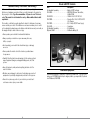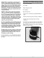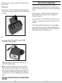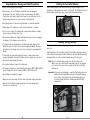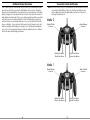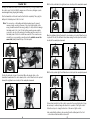
1
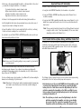
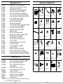
RTF Instruction Manual
EFLH3000
E-flite products are distributed exclusively by
Horizon Hobby, Inc.
4105 Fieldstone Road
Champaign, IL 61822
USA
© 2009 Horizon Hobby, Inc.
®
US patent D578,146
US patent number 7, 391, 320
Multiple patents pending
Horizon Hobby UK
Units 1-4 Ployters Rd
Staple Tye
Harlow, Essex
CM18 7NS
United Kingdom
Horizon Hobby Deutschland GmbH
Hamburger Strasse 10
25335 Elmshorn
Germany
DSM and DSM2 are trademarks or registered trademarks of Horizon Hobby, Inc.
The Spektrum trademark is used with permission of Bachmann Industries, Inc.
Spektrum radios and accessories are exclusively available from Horizon Hobby, Inc.
E-fliteRC.com
15762
Printed 6/09
Note: Attempting to fly the helicopter without completely reading the manual
may cause injury to yourself and people in the vicinity, as well as damage to
the helicopter.
Specifications
Length. . . . . . . . . . . . . . . . . . . . . 7.5 in (190mm)
Height. . . . . . . . . . . . . . . . . . . . . 3.5 in (90mm)
Main Rotor Diameter . . . . . . . . . . 7.0 in (180mm)
Weight with Battery . . . . . . . . . . . 1.0 oz (28 g)
Main Motor . . . . . . . . . . . . . . . . . Coreless (1 installed)
Tail Motor . . . . . . . . . . . . . . . . . . Micro coreless (1 installed)
Battery . . . . . . . . . . . . . . . . . . . . 120mAh 1-cell 3.7V 14C battery Li-Po (2 included)
Charger. . . . . . . . . . . . . . . . . . . . Celectra™ 4-port 1-cell 3.7V 0.3A DC Li-Po charger
(included)
Power Supply. . . . . . . . . . . . . . . . 6V, 1.5-amp AC/DC power supply (included)
Transmitter . . . . . . . . . . . . . . . . . MLP4DSM 2.4GHz DSM 4-channel (included)
Onboard Electronics. . . . . . . . . . . 5-in-1 receiver/servos/mixer/ESC/gyro (installed)
Table of Contents
Specifications . . . . . . . . . . . . . . . . . . . . . . . . . . . . . . . . . . . . . . . . . . . . . . . . . . . 1
Introduction. . . . . . . . . . . . . . . . . . . . . . . . . . . . . . . . . . . . . . . . . . . . . . . . . . . . . 3
Warning. . . . . . . . . . . . . . . . . . . . . . . . . . . . . . . . . . . . . . . . . . . . . . . . . . . . . . . . 3
Note on Lithium Polymer Batteries. . . . . . . . . . . . . . . . . . . . . . . . . . . . . . . . . . . . . 3
Additional Safety Precautions and Warnings. . . . . . . . . . . . . . . . . . . . . . . . . . . . . . 4
Blade mSR RTF Contents . . . . . . . . . . . . . . . . . . . . . . . . . . . . . . . . . . . . . . . . . . . 5
Additional Equipment . . . . . . . . . . . . . . . . . . . . . . . . . . . . . . . . . . . . . . . . . . . . . . 5
Preparing for First Flight. . . . . . . . . . . . . . . . . . . . . . . . . . . . . . . . . . . . . . . . . . . . 6
Flying Checklist . . . . . . . . . . . . . . . . . . . . . . . . . . . . . . . . . . . . . . . . . . . . . . . . . . 6
Battery Warnings and Guidelines. . . . . . . . . . . . . . . . . . . . . . . . . . . . . . . . . . . . . . 7
Celectra 4-Port 1-Cell 3.7V 0.3A DC Li-Po Charger Instructions . . . . . . . . . . . . . . . . 9
Celectra 4-Port Li-Po Charger Warning. . . . . . . . . . . . . . . . . . . . . . . . . . . . . . . . . 11
Usage Guidelines, Warnings and Safety Precautions. . . . . . . . . . . . . . . . . . . . . . . 12
Installing the Transmitter Batteries. . . . . . . . . . . . . . . . . . . . . . . . . . . . . . . . . . . . 13
Installing the Flight Battery . . . . . . . . . . . . . . . . . . . . . . . . . . . . . . . . . . . . . . . . . 13
Additional Binding Information. . . . . . . . . . . . . . . . . . . . . . . . . . . . . . . . . . . . . . . 14
Transmitter Control Identification. . . . . . . . . . . . . . . . . . . . . . . . . . . . . . . . . . . . . 15
Control Test. . . . . . . . . . . . . . . . . . . . . . . . . . . . . . . . . . . . . . . . . . . . . . . . . . . . 16
Important Channel 5 Information. . . . . . . . . . . . . . . . . . . . . . . . . . . . . . . . . . . . . 19
5-in-1 Control Unit Description, Arming and Motor Control Test. . . . . . . . . . . . . . . . 19
Understanding the Primary Flight Controls . . . . . . . . . . . . . . . . . . . . . . . . . . . . . . 23
Dual Rates. . . . . . . . . . . . . . . . . . . . . . . . . . . . . . . . . . . . . . . . . . . . . . . . . . . . . 27
Choosing a Flying Area. . . . . . . . . . . . . . . . . . . . . . . . . . . . . . . . . . . . . . . . . . . . 27
Optional Training Gear Installation . . . . . . . . . . . . . . . . . . . . . . . . . . . . . . . . . . . . 28
Flying the Blade mSR. . . . . . . . . . . . . . . . . . . . . . . . . . . . . . . . . . . . . . . . . . . . . 30
Advanced Swashplate Settings . . . . . . . . . . . . . . . . . . . . . . . . . . . . . . . . . . . . . . 33
Precision Swashplate Calibration Tool . . . . . . . . . . . . . . . . . . . . . . . . . . . . . . . . . 33
Transmitter and Receiver Binding. . . . . . . . . . . . . . . . . . . . . . . . . . . . . . . . . . . . . 34
Troubleshooting Guide . . . . . . . . . . . . . . . . . . . . . . . . . . . . . . . . . . . . . . . . . . . . 36
Exploded View Parts Listing . . . . . . . . . . . . . . . . . . . . . . . . . . . . . . . . . . . . . . . . 38
Exploded View. . . . . . . . . . . . . . . . . . . . . . . . . . . . . . . . . . . . . . . . . . . . . . . . . . 39
Replacement Parts List. . . . . . . . . . . . . . . . . . . . . . . . . . . . . . . . . . . . . . . . . . . . 40
Optional Parts List. . . . . . . . . . . . . . . . . . . . . . . . . . . . . . . . . . . . . . . . . . . . . . . 40
Replacements and Optional Parts . . . . . . . . . . . . . . . . . . . . . . . . . . . . . . . . . . . . 41
Warranty Information . . . . . . . . . . . . . . . . . . . . . . . . . . . . . . . . . . . . . . . . . . . . . 42
Product Registration. . . . . . . . . . . . . . . . . . . . . . . . . . . . . . . . . . . . . . . . . . . . . . 45
FCC Information. . . . . . . . . . . . . . . . . . . . . . . . . . . . . . . . . . . . . . . . . . . . . . . . . 45
CE Compliance Information for the European Union. . . . . . . . . . . . . . . . . . . . . . . . 46
2
Introduction
Weighing in at under an ounce, the Blade® mSR Ready-To-Fly takes ultra-micro
helicopter performance to the next level. Its unique Bell-Hiller rotor head design
provides the kind of speed and agility you would expect of a single-rotor heli but
maintains a measure of positive stability similar to a co-axial heli. This blend of agility
and stability makes it the ideal “next step” for someone moving up from a coaxial
heli, such as the Blade CX3 or Blade mCX.
Your Blade mSR RTF comes from the factory completely assembled and flight tested
with everything you need to get flying. This includes a 2.4GHz DSM2™ transmitter,
two Li-Po flight batteries, a convenient 4-port DC Li-Po charger with an AC adapter
and 4 AA batteries for the transmitter. The mSR’s onboard 5-in-1 control unit
combines the functions of a Spektrum™ 2.4GHz DSM2-compatible receiver, mixer,
gyro, main and tail motor ESCs and servos. This integration eliminates the need
for difficult electronic installation and setup while providing heading lock-like gyro
performance and precise proportional motor and servo response.
While your mSR is ready-to-fly right from the box, please take the time to read
through this manual for tips on battery safety and charging, control checks and more
before making your first flight. We also suggest viewing the Instructional Video by
clicking the link located on the product page for the Blade mSR at www.e-fliterc.com.
Warning
An RC helicopter is not a toy! If misused, it can cause serious bodily harm and
damage to property. Fly only indoors, in open areas following all instructions and as
recommended in this manual. Keep loose items that can get entangled in the rotor
blades away from the main and tail blades, including loose clothing, or other objects
such as pencils and screwdrivers. Especially keep your hands away from the rotor
blades.
Note on Lithium Polymer Batteries
Lithium Polymer batteries are significantly more volatile than alkaline
or Ni-Cd/Ni-MH batteries used in RC applications. All manufacturer’s
instructions and warnings must be followed closely. Mishandling of
Li-Po batteries can result in fire. Always follow the manufacturer’s
instructions when disposing of Lithium Polymer batteries.
3
Additional Safety Precautions and Warnings
As the user of this product, you are solely responsible for operating it in a manner
that does not endanger yourself and others or result in damage to the product or
the property of others. Age Recommendation: 14 years or over. This is not
a toy. This product is not intended for use by children without direct adult
supervision.
This model is controlled by a radio signal that is subject to interference from many
sources outside your control. This interference can cause momentary loss of control
so it is advisable to always keep a safe distance in all directions around your model, as
this margin will help to avoid collisions or injury.
Blade mSR RTF Contents
Item
Description
Not Available Separately. . . . . . . . . . . . . . Blade mSR RTF airframe
EFLH1064. . . . . . . . . . . . . . . . . . . . . . . . MLP4DSM 4-Channel Transmitter,
2.4GHz DSM2
EFLB1201S. . . . . . . . . . . . . . . . . . . . . . . 120mAh 1-Cell 3.7V 14C Li-Po
EFLC1004. . . . . . . . . . . . . . . . . . . . . . . . Celectra 4-Port 1-Cell 3.7V 0.3A DC
Li-Po Charger
EFLC1005. . . . . . . . . . . . . . . . . . . . . . . . 6V, 1.5-Amp AC/DC Power Supply
EFLH1209. . . . . . . . . . . . . . . . . . . . . . . . Screwdriver
Not Available Separately. . . . . . . . . . . . . . 4 AA Batteries
(Optional) FUG4. . . . . . . . . . . . . . . . . . . . AA Alkaline Battery (4)
• Never operate your model with low transmitter batteries.
• Always operate your model in an open area away from cars,
traffic, or people.
• Avoid operating your model in the street where injury or damage
can occur.
• Never operate the model out into the street or populated areas
for any reason.
• Carefully follow the directions and warnings for this and any optional
support equipment (chargers, rechargeable battery packs, etc.) that
you use.
• Keep all chemicals, small parts and anything electrical out of the
reach of children.
• Moisture causes damage to electronics. Avoid water exposure to all
equipment not specifically designed and protected for this purpose.
• Never lick or place any portion of your model in your mouth as it
could cause serious injury or even death.
4
Additional Equipment
No additional equipment is required to complete your Blade mSR. If you choose to
make your EFLC1004 Celectra 4-port charger portable, you may install (4) optional
size D Batteries (FUG7100).
5
Preparing for First Flight
Please note this checklist is not intended to be a replacement for the content
included in this instruction manual. Although it can be used as a quick start guide,
we strongly suggest reading through this manual completely before proceeding.
• Remove and inspect contents
• Read EFLC1004 Charger instructions (page 9) prior to charging the included Li-Po
batteries
• Read this instruction manual thoroughly
• Install the included four AA batteries in the transmitter
• Install the flight battery in the helicopter (once it has been fully charged)
• Test the controls (shown on page 16 of this manual)
• Familiarize yourself with the controls
Battery Warnings and Guidelines
While the Celectra 4-Port 1-Cell 3.7V 0.3A DC Li-Po Charger has been
specifically designed to safely charge the E-flite and ParkZone single-cell
3.7V Lithium Polymer batteries such as EFLB1201S and PKZ3001, you
MUST read the following safety instructions and warnings before handling,
charging or using the Li-Po battery.
Note: Lithium Polymer batteries are significantly more
volatile than the alkaline, Ni-Cd or Ni-MH batteries used in RC
applications. All instructions and warnings must be followed
exactly. Mishandling of Li-Po batteries can result in fire.
By handling, charging or using the included Li-Po battery, you assume
all risks associated with lithium batteries. If you do not agree with these
conditions, return your complete mSR along with the Celectra 4-Port 1-Cell
3.7V 0.3A DC Li-Po Charger (EFLC1004), in unused condition to the place
of purchase immediately.
• You must charge 1-cell 3.7V Li-Po batteries in a safe area away from flammable
materials.
• Find a suitable area for flying
Flying Checklist
Please note this checklist is not intended to be a replacement for the content
included in this instruction manual. Although it can be used as a quick start guide,
we strongly suggest reading through this manual and other documentation included
with the product completely before proceeding.
•A
lways turn the transmitter on first and set at least 2 feet away from the
aircraft
• Install the flight battery into the mSR’s battery mount with the tab side down, red
dot up
• Connect the flight battery into the power lead of the 5-in-1 control unit
•A
llow the 5-in-1 control unit to initialize and arm properly. DO NOT MOVE,
SWAY or PRETEND TO FLY THE HELICOPTER DURING INITIALIZATION.
(Shown on page 19 of this manual)
• Fly the model
• Land the model
• Disconnect the flight battery from the 5-in-1 control unit
• Always turn the transmitter off last
• Never charge the battery unattended. When charging the battery you should always
remain in constant observation to monitor the charging process and react to
potential problems that may occur.
• After flight, the Li-Po batteries must be cooled to the ambient temperature before
charging.
• If at any time during the charge or discharge process the battery begins to balloon
or swell, discontinue charging or discharging immediately. Quickly and safely
disconnect the battery, then place it in a safe, open area away from flammable
materials to observe it for at least 15 minutes. Continuing to charge or discharge
a battery that has begun to balloon or swell can result in a fire. A battery that
has ballooned or swollen even a small amount must be removed from service
completely.
• Store the battery at room temperature in a dry area for best results.
• When transporting or temporarily storing the battery, the temperature range should
be from 40–120 degrees Fahrenheit. Do not store the battery or model in a car
or direct sunlight whenever possible. If stored in a hot car, the battery can be
damaged or even catch fire.
• Do not over-discharge the Li-Po flight battery. Discharging the battery too
low can cause damage to the battery resulting in reduced power, duration
or failure of the battery entirely.
• Li-Po cells should not be discharged to below 3V each under load. In the
case of the 1-cell Li-Po battery used for the Blade mSR, you will not want
to allow the battery to fall to below 3V during flight.
6
7
The Blade mSR’s 5-in-1 control unit features a soft low voltage cutoff
(LVC) that occurs when the battery reaches 3V under load. When the soft
cutoff occurs, the ESC of the 5-in-1 unit will reduce power to the motors
(regardless of the power level you have set with the throttle stick) and the
BLUE LED will blink in order to prevent the voltage of the battery from
dropping below 3V. This reduction in power usually requires that you land
the model immediately, at which point you should power down the model
and unplug the flight battery.
Celectra 4-Port 1-Cell 3.7V 0.3A DC Li-Po Charger Instructions
LED functions under normal operation:
• Solid – Charging
• Blinking – Charging nearly complete
• Off – Fully Charged
And while it is possible to power the model up and to fly again after the
soft LVC occurs, this is NOT recommended as continued discharging to
the soft LVC will cause permanent damage to the Li-Po battery that results
in lost power and duration when using the battery for subsequent fights,
or failure of the battery entirely. Continued attempts to further discharge
the battery may also result in loss of control while the motors are running
as the voltage of the battery may drop below the minimum operating
voltage of the receiver and other electronics.
Replace D-size batteries when:
Also, it is not recommended that you fly to the soft LVC every time you fly.
Instead, you should be aware of the power level of the battery/helicopter
throughout the flight, and if at any time the helicopter begins to require
more throttle than typical to maintain hover or flight, you should land the
helicopter immediately. Routinely discharging the battery to the soft LVC
can still cause permanent damage to the battery.
It is important that you only charge E-flite and ParkZone 1-Cell 3.7V Li-Po Batteries,
used in our ultra-micro flyers, with the Celectra 4-Port 1-Cell 3.7V 0.3A DC Li-Po
Charger (EFLC1004). Please familiarize yourself thoroughly with the Battery Warnings
and Guidelines section before continuing.
• LED remains solid for over 60 minutes when charging (70mAh–120mAh) Li-Po
batteries
• LED remains solid after removing single-cell Li-Po batteries from individual ports.
• LED remains off after inserting discharged single-cell Li-Po batteries
inindividual ports.
Note: When the battery power/voltage is getting low, you will typically find
that significant rudder trim and/or rudder stick adjustments are needed
to prevent the helicopter from spinning. This usually occurs before soft
LVC and indicates a good time to stop flying.
If you have any further questions or concerns regarding the handling, charging and/
or use of the included Li-Po battery pack, please contact the Horizon Support Team
at 877-504-0233.
8
9
Please follow these steps to charge your single-cell Li-Po battery with the Celectra
4-port Li-Po charger.
FOR PORTABLE USE:
• Remove the cover on the bottom of the charger and install four D-size batteries
(not included), noting proper polarity. Replace the cover after the Alkaline batteries
are installed.
Celectra 4-Port Li-Po Charger Warning
Lithium Polymer (Li-Po) batteries are significantly more volatile than other
rechargeable batteries used in RC applications. Failure to read and follow these
instructions and safety precautions may result in fire, personal injury and damage to
property.
E-flite, Horizon Hobby, Inc., its retailers, and any other representatives, assume
absolutely no liability for use of this product or failure to comply with these
instructions and precautions.
If you are not prepared to accept complete liability for the purchase and/or use of
this product, you are advised to return it new and unused to the place of purchase
immediately.
Never ship batteries without the expressed permission of the recipient. Batteries
carrying a charge of 25% or more cannot be shipped safely. Batteries which are
damaged cannot be shipped safely. Damage or loss due to unsafe shipping is the
legal responsibility of the person who shipped the product.
OR
• Use the included E-flite 6V, 1.5-Amp AC/DC Power Supply (EFLC1005/
EFLC1005AU/EFLC1005EU/EFLC1005UK).
NEVER attempt to power the charger from an AC outlet without the use of a
proper AC to DC adapter/power supply.
Note: When using the AC to DC adapter/power supply, the Celectra 4-Port
Charger is designed to bypass the D-size battery circuitry to prevent damage.
Do not insert charged or discharged Li-Po batteries in any of the charge ports if
the power supply is connected to the 4-port charger while power supply is not
connected to a power source. Doing so will discharge and possibly damage the
batteries.
NEVER LEAVE THE ADAPTER/POWER SUPPLY OR CHARGER PLUGGED IN
UNATTENDED.
10
11
Usage Guidelines, Warnings and Safety Precautions
• Always inspect batteries before charging.
• Never charge or use a Li-Po battery or pack that shows any damage or
disfigurement of any kind. Swelling is a sign of internal damage. Any breach
of protective cover, wiring or plugs is also reason to discontinue use. See the
manufacturer’s instructions for proper disposal of Li-Po batteries.
Installing the Transmitter Batteries
Install four AA batteries in the transmitter. Check for proper operation of the
transmitter by switching the power switch on (to the left). The LED light at the top of
the transmitter should begin to glow solid red while the transmitter beeps.
• Never charge near or in the area of any flammable or combustible materials.
• Always charge Li-Po batteries in or on fire resistant materials or containers.
• Do not store or charge Li-Po batteries with or around other batteries or battery
packs of any type, including other Li-Pos.
• Never leave the battery and charger unattended while in use. Improper charging or
discharging of Li-Po batteries could result in fire.
• Constantly monitor the temperature of the battery pack while charging. If the
battery becomes hot to the touch discontinue charging immediately. Disconnect
the battery from the charger and observe it in a safe place for approximately 15
minutes.
• If at any time you see a battery starting to balloon or swell up, discontinue
charging immediately. Disconnect the battery from the charger and observe it in a
safe place for approximately 15 minutes.
• Do not allow children to charge Li-Po battery packs.
• This charger is designed for 1-cell Lithium-Polymer batteries ONLY. It MUST NOT be
used to charge other size Li-Po batteries, Ni-MH or Ni-Cd battery packs.
• Never attempt to dismantle the charger.
• Always disconnect the charger from the power supply after charging the battery.
• Disposal of Li-Po batteries requires special care. Follow the manufacturer’s
instructions for safe disposal.
12
Installing the Flight Battery
Once the Li-Po battery has been fully charged, it’s ready to be installed in the
helicopter.
Install the battery in the helicopter by sliding it into the battery mounting supports/
slots just below the main gears. Slide the battery into the slots with the label facing
downward and the connector oriented toward the back of the helicopter.
Note: B
e sure to slide the battery into the slots until the endcap of the
battery comes into contact with the rear battery support. This will allow
you to achieve the correct center of gravity for the best overall flight
performance.
Important: In the event of a hard landing or crash, the flight battery may move
slightly. Check the flight battery and ensure it is installed properly
prior to flying. Flying the helicopter with the battery slightly out
of position changes the Center of Gravity and may affect flight
characteristics.
13
Additional Binding Information
Prior to each flight, you should ensure that you power on your transmitter and wait
about five seconds before you plug the flight battery into the receiver. Doing this
allows time for the transmitter to scan and secure two open frequencies. If the flight
battery is plugged in too quickly and the link is missed, it may cause the receiver to
inadvertently enter bind mode. If this occurs simply leave the transmitter on and then
disconnect and reconnect the flight battery. Once the flight battery is plugged in,
put the helicopter on a horizontal surface as soon as you can (within two seconds)
for gyro calibration. Some customers find it easier to lay the helicopter on its side
while connecting the flight battery, then leaving it on its side during the initialization
process. Do not move/sway the helicopter during the calibration process. Failure to
do this will cause unstable flight performance.
Transmitter Control Identification
Note: E
ach time before you fly you should ALWAYS turn the transmitter on before
connecting the flight battery to the 5-in-1 unit. After each flight, be sure
that you always disconnect the flight battery from the 5-in-1 unit before
powering the transmitter off.
Mode 2
Rudder/Throttle
Functions
Aileron/Elevator
Functions
Rudder Trim Buttons
Throttle Trim Buttons
Aileron Trim Buttons
Elevator Trim Buttons
Mode 1
Rudder/Elevator
Functions
Aileron/Throttle
Functions
Rudder Trim Buttons
Elevator Trim Buttons
14
Aileron Trim Buttons
Throttle Trim Buttons
15
Control Test
Although each Blade mSR model is test flown at the factory, it is a good idea to test
the controls prior to the first flight to ensure none of the servos, linkages or parts
were damaged during shipping and handling.
With the stick pulled back, the right-hand servo should push the swashplate upward.
Mode 2
Turn the transmitter on first and lower the throttle stick completely. Then, plug the
battery into the battery lead of the 5-in-1 unit.
Note: T
he connectors on the battery and battery lead are keyed to prevent
reverse polarity connection. However, if you force them together in the
wrong orientation and with the wrong polarity, it is still possible to damage
the battery and/or 5-in-1 unit. To help further prevent a reverse polarity
connection, one side of the endcap on the battery and the connector on
the battery lead of the 5-in-1 unit will have a red dot. The connectors are
oriented for a proper polarity connection when the red dots are on the
same side (usually toward the top of the helicopter).
Mode 2
Mode 1
Move the right-hand stick left and right to check aileron roll control. When the stick
is pushed to the left, the left-hand servo (when viewing the helicopter from behind)
should pull the swashplate downward.
Mode 2
Mode 1
Mode 1
With the stick pushed right, the left-hand servo should push the swashplate upward.
Position the helicopter to view it from behind. Move the elevator stick on the
transmitter forward and aft to check elevator pitch control. When the stick is pushed
forward, the right-hand servo should pull the swashplate downward.
Mode 2
Mode 2
Mode 1
Mode 1
If at any time during the test the controls respond in the opposite direction, it may
be necessary to reverse/change the direction of operation of the flight controls.
Follow these steps to change the direction of the various flight controls:
• Be certain that the battery is disconnected from the battery lead of the 5-in-1
control unit and the transmitter is turned off.
16
17
• Push down on the appropriate digital trim button on the transmitter for the control
you would like to change the direction of. For example:
Top elevator trim button—elevator channel normal
Bottom elevator trim button—elevator channel reversed
Left aileron trim button—aileron channel normal
Right aileron trim button—aileron channel reversed
• Continue to hold the appropriate trim button while turning the transmitter on.
• Hold the digital trim button down for approximately five seconds, until a series of
beeps/tones are heard confirming the selection.
• Connect the battery to the 5-in-1 and complete the flight control test, confirming
that all controls are operating in the correct directions.
If you decide to use an E-flite LP5DSM or HP6DSM transmitter, please position your
channel reversal dip switches as follows:
Important Channel 5 Information
• Channel 5 affects rate settings of the 5-in-1 Control Unit.
• If using the stock MLP4DSM Transmitter, this information is not pertinent.
• If using an LP5DSM or HP6DSM Transmitter, please turn the Channel 5 knob
clockwise completely.
• If using any other DSM2 compatible transmitter, please ensure Channel 5 is set to
default servo reversal and the switch or knob is set to a position that allows full
travel control.
Note: T
his can easily be tested by inducing full cyclic (Aileron/Elevator) input and
moving the switch or knob. There’s approximately 15% less servo travel
depending on what position Channel 5 is in.
5-in-1 Control Unit Description, Arming and Motor Control Test
The unique 5-in-1 Control Unit installed on your Blade mSR is a lightweight
combination of main motor and tail motor electronic speed controls, mixer, gyro,
servos and Spektrum DSM2 compatible receiver. The 5-in-1 unit is also equipped
with a BLUE status indicator LED.
LP5DSM Transmitter
HP6DSM Transmitter
Note: K
eep a record of the existing settings in case you want to go back and fly
your other aircraft.
Once you’ve reconfirmed the flight control directions, all controls should be
functioning properly. However, if you continue to encounter any problems with
your Blade mSR responding properly to the transmitter, do not fly. Call the Horizon
Support Team at 1-877-504-0233.
If you’ve confirmed proper control operation of your Blade mSR, continue reading the
manual prior to attempting to fly the helicopter.
The following checklist contains the steps you must follow to ensure proper arming
and operation of the 5-in-1 unit, as well as proper motor response.
Note: A
ttempting to fly the helicopter without completely reading the manual may
cause injury to yourself and people in the vicinity, as well as damage to
the helicopter.
•E
ach time before you fly you should ALWAYS turn the transmitter on and
set at least 2 feet away from the aircraft before connecting the flight
battery to the 5-in-1 unit. Never connect the flight battery to the 5-in-1
unit before powering the transmitter on first. After each flight, be sure
that you always disconnect the flight battery from the 5-in-1 unit before
powering the transmitter off.
18
Note: T
he only time you should connect the flight battery to the 5-in-1
unit before powering the transmitter on is when you are binding
the receiver of the 5-in-1 unit to the transmitter. Please see the
Transmitter and Receiver Binding section of this manual for more
19
information. Some customers find it easier to lay the helicopter on
its side while connecting the flight battery, then leaving it on its side
during the initialization process.
•T
he throttle stick MUST be set in the lowest possible position, and the
throttle trim must be set to the middle or a lower than middle position (the
middle position is indicated by a longer than usual beep/tone), in order
for the 5-in-1 unit to arm.
•T
he rudder stick MUST be left NEUTRAL (CENTER STICK), and the rudder
trim must be set to the middle position (the middle position is indicated
by a longer than usual beep/tone), in order for the 5-in-1 unit to arm
properly
If this is the first test flight, or a test flight following repairs, you should also center
the rudder, aileron and elevator trims.
Set throttle
stick at lowest
possible position.
Mode 2
Mode 1
Set throttle
stick at lowest
possible position.
• When the status LED becomes solid blue, the 5-in-1 unit is initialized and ready
for flight. Also, as long as you had the throttle stick and trim set to the correct
positions during the initialization process, the ESC/motors will now be armed.
Use caution as both main rotor and tail rotor blades will now spin with throttle
stick input.
Note: If the status LED does not become solid blue, please review the
following.
• If after the status LED becomes solid BLUE, but you have no control of the motors,
you have a positive Radio Frequency (RF) link between the transmitter and receiver,
but the throttle stick and throttle trim may not be set to the correct positions.
Check to be sure that the throttle stick is in the lowest possible position, and that
the throttle trim is set to the middle or a lower than the middle position. If you now
have control of the motors, proceed to the next step of the checklist.
• If the status LED turns off completely, you do not have a positive RF link between
the transmitter and receiver. Check to be sure that the transmitter has been
powered on and that the LED indicator on the transmitter is glowing solid red.
If the transmitter is powered on and functioning properly, disconnect the flight
battery from the 5-in-1 unit, move the transmitter at least 2 feet away from the
aircraft, then reconnect the flight battery. Now the 5-in-1 unit should initialize and
arm properly.
If your 5-in-1 unit will not initialize and arm after following the guidelines as listed
above, call the Horizon Support Team at 1-877-504-0233.
Rudder Trim Buttons
Aileron Trim Buttons
Throttle Trim Buttons
Elevator Trim Buttons Elevator Trim Buttons
Rudder Trim Buttons
Aileron Trim Buttons
Throttle Trim Buttons
• After confirming that the transmitter has been turned on and that the LED is
glowing solid red, it is now safe to connect the flight battery to the 5-in-1 unit.
•W
ith battery power applied to the 5-in-1 unit, the status indicator LED
should glow solid blue, then blink, then become solid blue again.
Note: It is extremely important that you do not move, sway, or pretend to
fly the helicopter once the flight battery is connected because the
initialization process and calibration of the gyro has begun. If you
do move the helicopter before the LED is solid BLUE, disconnect
the flight battery from the 5-in-1 unit and repeat the initialization
process.
•O
nce you have placed the helicopter in a safe area, free of obstructions,
and are clear of the rotor blades, you can safely begin to power up the
model to check for proper operation of the motors.
Note: A
ttempting to fly the helicopter without completely reading the
manual may cause injury to yourself and people in the vicinity, as
well as damage to the helicopter.
Once you have placed the helicopter in a safe area, free of obstructions, and are
clear of the main and tail rotor blades, you can safely begin to power up the model
to check for proper operation of the motors.
• Advance the throttle stick upward slowly, just until both main and tail rotor blades
begin to spin. DO NOT attempt the fly the helicopter at this time. Note the
direction that the main and tail rotor spins. When viewed from the top, the main
rotor blades should spin clockwise. When viewed from the right-hand side of the
helicopter, the tail rotor should spin counter clockwise. If either one of the rotors is
operating in the wrong direction, disconnect the battery and reverse the polarity of
the corresponding motor’s input power leads.
• After confirming that the direction of rotation for both main and tail rotors is
correct, it is best to confirm that the tail rotor respond properly to rudder
control inputs.
20
21
With the rotors spinning at a low level of power, move the rudder stick slightly to
the right. This should cause the speed of the tail rotor to increase.
Next, move the rudder stick all the way to the left. This should cause the speed
of the tail rotor to decrease. If the tail rotor is not properly responding to rudder
input, simply reverse the rudder channel on the transmitter. However, please be
sure to review the following sections of the manual BEFORE proceeding with the
first flight.
Note: A
ttempting to fly the helicopter without completely reading the
manual may cause injury to yourself and people in the vicinity, as
well as damaging the helicopter.
Understanding the Primary Flight Controls
If you are not familiar with the controls of your Blade mSR, please take a
few minutes to familiarize yourself with them before attempting your first
flight.
When the throttle stick is in the lowest possible position and throttle trim is set to the
middle or a lower-than-middle position, the main rotor blades will not spin. Advancing
the stick upward will increase the speed of the main rotor blades. Increasing the
speed of the main rotor blades will cause the model to climb.
Mode 2
Climb
Mode 1
Decreasing the speed of the main rotor blades by lowering the throttle stick will
cause the model to descend.
Mode 2
Descend
Mode 1
After lifting the model off the ground you can balance the throttle by carefully moving
the throttle stick up and down so the model will hold a stationary hover without
climbing or descending.
22
23
Moving the left-hand stick to the left will turn (yaw) the nose of the helicopter to the
left about the axis of the main shaft.
Mode 2
Nose Yaw Left
The elevator stick controls fore and aft pitch of the helicopter. Pushing the stick
forward will pitch the nose of the helicopter downward, allowing the helicopter to be
flown forward.
Mode 2
Helicopter Moves Forward
Mode 1
Mode 1
Moving the left-hand stick to the right will turn (yaw) the nose of the helicopter to
the right about the axis of the main shaft.
Mode 2
Nose Yaw Right
Pulling the elevator stick backward will pitch the tail of the helicopter downward,
allowing the helicopter to be flown backward.
Mode 2
Helicopter Moves Backward
Mode 1
Mode 1
The rudder trim can be used to help keep the nose of the helicopter from rotating to
the left or right when in hover with no rudder stick input. For example, if the nose of
the helicopter drifts to the right when in hover, add left rudder trim (by pressing the
left-hand rudder trim button) until the nose stays as close to straight as possible.
24
The elevator trim can be used to help keep the helicopter from drifting forward or
backward when in hover with no elevator stick input. For example, if the helicopter
drifts forward when in hover, add back/up elevator trim until the helicopter hovers
as level as possible with no forward drifting.
25
Moving the aileron stick to the left will roll the helicopter to the left, allowing the
helicopter to be flown sideways towards the left when viewing the helicopter
from behind.
Mode 2
Helicopter Slides Left
The MLP4DSM transmitter included with your Blade mSR is equipped with a dual rate
feature. This feature allows the pilot to toggle between the high and low control rates
available for the aileron, elevator and rudder channels. You can toggle between the
high and low rates by pushing in on the right-hand stick on the transmitter (while the
transmitter is powered on).
When the transmitter is first powered on it will be in the high-rate mode. You can tell
you are in the high-rate mode when the LED on the transmitter glows solid red. In
the high-rate mode the controls are allowed to reach their maximum values, which
is typically preferred by experienced pilots interested most in maximum control
authority.
Mode 1
Moving the aileron stick to the right will roll the helicopter to the right, allowing the
helicopter to be flown sideways towards the right when viewing the helicopter
from behind.
Note: T
his command does not cause the nose of the helicopter to turn! Rather,
it causes the helicopter to bank, and then slide left or right. Use of the
rudder stick (the left stick) is required to point the nose of the helicopter in
the desired direction.
Mode 2
Dual Rates
Helicopter Slides Right
Mode 1
By pushing in on the right-hand stick while in the high-rate mode, you can enter
the low-rate mode. You can tell you are in the low-rate mode when the LED on the
transmitter blinks continuously. The low-rate mode is typically preferred by (and
best for) first-time, low-time and other pilots interested most in a reduced amount of
control that allows for smoother and more easily controlled hovering and flying.
Note: Y
ou may be required to make slight trim changes when switching back and
forth between low and high rates.
Choosing a Flying Area
When you are ready for your first flight, you will want to select a relatively open
indoor area that is free of people and obstructions. And while it is possible for
experienced pilots to fly the Blade mSR in relatively small indoor areas with great
success due to its size and controllability, we strongly recommend an area with at
least 10-feet by 10-feet of floor space and no less than 8-foot ceilings when making
your first few flights.
Once you have properly trimmed your helicopter and become familiar with its
handling and capabilities, you will be able to fly in other smaller, less open areas.
The aileron trim can be used to help keep the helicopter from drifting left or right
when in hover with no aileron stick input. For example, if the helicopter drifts to
the right when in hover, add left aileron trim until the helicopter hovers as level as
possible with no drifting to the right.
Note: T
he Blade mSR is designed to be flown INDOORS and can be
successfully flown OUTDOORS by an EXPERIENCED PILOT with
CALM WIND CONDITIONS UP TO 5 MPH.
Once you’re familiar with the primary controls of the helicopter, you are almost ready
to fly.
26
27
Optional Training Gear Installation
If you are transitioning from a coaxial helicopter, or you are a beginner
helicopter pilot, you may consider installing the optional training gear designed for
your Blade mSR.
• Place training gear assembly under the helicopter above the skids, as shown in the
photo below
The training gear may help prevent excessive damage by keeping your helicopter as
level as possible in the event of a “bail out” (losing orientation and cutting the throttle
completely off).
The training gear is most effective when keeping the helicopter at or below 2 feet
and flown at low speeds. The training gear is not designed as a “force field” or
“protective armor” to help prevent any damage during a crash. However, it is a
great tool to help prevent damage to your helicopter when used properly.
• Slide one O-ring on each training gear rod
• Slide each O-ring over the landing gear skids to secure the training gear to the
helicopter
• Insert each training gear rod into the training gear hub
28
29
Flying the Blade mSR
Note: A
ttempting to fly the helicopter without completely reading the manual may
cause injury to yourself and people in the vicinity, as well as damage to the
helicopter.
Having followed the proper 5-in-1 control unit initialization and arming procedures,
confirmed proper control of the servos and motors, and found a suitable flying area,
your Blade mSR is ready for flight.
Note: In addition to reviewing the flight maneuvers outlined below, we recommend
that you watch the Instructional Video located on the product page for the
Blade mSR on www.horizonhobby.com to see many of these maneuvers
and adjustments performed by the helicopter and pilot.
The Blade mSR is a stable helicopter ideal for pilots who have been successful with
the mCX or other coaxial helicopters. Although the Blade mSR is stable, it can easily
be flown too fast and may cause you to fall behind the proper control inputs.
Team Tips: W
e highly recommend you begin by using very slight control inputs
to get familiarized with the feel and performance of the mSR. Using
maximum control inputs will make it very hard to get familiarized
with the mSR.
Keep the tail towards yourself when flying the mSR for the first time so that your
forward/backward and left/right controls can easily be recognized and orientation
of the helicopter will not be lost. The Blade mSR has helped many new hobbyists
transition from coaxial helicopters to fast moving high performance single-rotor
helicopters. Patience will help ensure your success in the R/C helicopter hobby.
Please visit us on the web at www.horizonhobby.com for instructional videos and
other information regarding your Blade mSR.
• If you are transitioning from a coaxial helicopter, or you are a beginner helicopter
pilot, you may consider installing the specially designed training gear, available
separately for your Blade mSR. Follow page 27 of this instruction manual for
installation instructions.
• Slowly raise the throttle stick, increasing the speed of the main rotor blades until
the model begins to lift off. Do not raise the throttle stick too quickly as the model
could climb too fast causing you to lose control or make contact with objects
above.
• Lift the model off the ground just a few inches and concentrate on balancing the
throttle (left-hand) stick position so that the model holds a steady hover altitude. In
some cases it may be best to make a few short “hops” to an altitude of just a few
inches until you become familiar with the control inputs and trim settings required
to maintain a steady hover and altitude.
As you will find, the Blade mSR requires minor throttle adjustments to maintain
its altitude in hover. Remember to keep these throttle adjustments as minimal as
30
possible as large adjustments could result in a loss of control and/or a possible
crash.
• While attempting to establish a low-level hover, you can also check to see if
any trim adjustments are required to help keep the Blade mSR from constantly
drifting in various directions. If you find the helicopter constantly drifts without
any directional control input, it will be best to land the model before making any
adjustments to the trim settings. Additional details regarding the location and
function of the trim buttons can be found in the “Understanding the Primary Flight
Controls” section of this manual.
If the nose of the helicopter is drifting to the left or right, you will need to adjust the
rudder trim.
If the helicopter is drifting forward or backward, you will need to adjust the elevator
trim.
If the helicopter is drifting to the left or right, you will need to adjust the aileron
trim.
Continue to make trim adjustments until the helicopter can hover at a low altitude
with very little drifting and directional control input. If the Blade mSR is your first
helicopter model, it may be best to have the help of an experienced helicopter pilot
to trim the model for you before making your first flight.
• Once you have the Blade mSR properly trimmed and maintaining a stable low-level
hover, practice using the rudder, elevator and aileron controls to get a feel for how
the helicopter responds to control inputs. Remember to keep the control inputs as
minimal as possible to prevent over-controlling the helicopter, especially when in
hover.
After becoming comfortable with hovering the Blade mSR at low-levels of altitude just
a few inches off the ground, you can transition to hovering and flying the helicopter
at higher altitudes of approximately three to four feet. At these higher altitudes you
will be able to get a feel for the flight characteristics of the Blade mSR when it is
flying out of “ground effect.”
• If at any time during flight you feel like the helicopter is drifting out of control,
simply release all of the controls except for throttle. You will need to use the
throttle to maintain altitude, but due to the inherent stability of the specially
designed rotor head, the Blade mSR will simply return to a stable hover on its own
if space allows.
• Don’t be afraid to set the helicopter down on the ground quickly by lowering the
throttle when approaching walls or other obstacles to help prevent main rotor
blade strikes.
• IN THE UNFORTUNATE EVENT OF A CRASH OR ROTOR BLADE STRIKE,
NO MATTER HOW MINOR OR MAJOR, YOU MUST LOWER THE THROTTLE
STICK TO THE LOWEST POSSIBLE POSITION AS QUICKLY AS POSSIBLE TO
31
PREVENT DAMAGE TO THE ESC OF THE 5-IN-1 UNIT. YOU MUST ALSO BE
SURE THAT THE THROTTLE TRIM IS SET TO THE MIDDLE POSITION OR TO
A POSITION THAT IS LOWER THAN THE MIDDLE.
Advanced Swashplate Settings
Long Swashplate Control Balls
Failure to lower the throttle stick to the lowest possible position in the event
of a crash could result in damage to the ESC in the 5-in-1 unit, which may
require replacement of the 5-in-1 unit.
Short
Swashplate
Control Balls
Note: Crash damage is not covered under warranty.
• Once you have gained experience and confidence in hovering the Blade mSR, you
can attempt more advanced maneuvers including:
Forward Flight
Skidding Takeoffs
Backward Flight
Skidding Landings
Pirouettes
Spot Landings
The Blade mSR comes with an adjustable precision swashplate. Advanced pilots
may benefit from a more aggressive setup.
The more aggressive setup can be achieved by simply popping off the lower rotor
head links and moving them onto the longer set of inner swashplate control balls.
Precision Swashplate Calibration Tool
The Blade mSR includes a precision swashplate calibration tool. This tool should be
used after every crash or when rebuilding to ensure rotor head/swashplate linkages
are correctly spaced ensuring there is no drag within the pivot points of the rotor
head. Failure to properly calibrate your mSR may result in loss of stability and control
authority.
To use the precision swashplate calibration too:
• Clip on tool as shown on the photos.
• While the tool is in place, push up on the swashplate until the tool is sandwiched
between the swashplate and the upper rotor hub.
• Check to see that the flybar seesaws freely; then remove tool before flight.
32
33
Transmitter and Receiver Binding
NOTES
Binding is the process of programming the receiver to recognize the GUID (Globally
Unique Identifier) code of a single specific transmitter. If you ever find it is necessary
to replace the transmitter or the receiver/5-in-1 unit for your model, it will be
necessary for you to ‘bind’ the new transmitter or receiver/5-in-1 to your existing
transmitter or receiver/5-in-1 for proper operation.
The following steps outline the binding process:
• Make sure the flight battery is disconnected from the 5-in-1 unit and the transmitter
is turned off.
• Plug the flight battery into the 5-in-1 unit.
• Plug the flight battery into the 5-in-1 unit. After 5 seconds the LED on the 5-in1 unit
will begin flashing.
• After verifying the LED is flashing on the receiver/5-in-1, PUSH directly down on
the left-hand stick while switching the transmitter on (you will feel a ‘click’ when you
push in on the end of the stick).
• After approximately 5-10 seconds the receiver/5-in-1 should be bound to the
transmitter and you should now have full control and function.
If you encounter any problems, repeat the binding process again or call the
Horizon Support Team at 1-877-504-0233.
34
35
Troubleshooting Guide
Problem
Possible Cause
Solution
Aircraft will not
“throttle up” but
all other controls
seem to function.
• User did not lower
• Lower throttle stick and throttle
throttle trim and throttle
trim to their lowest settings.
stick prior to initializing
the aircraft.
Aircraft’s yaw/
• User did not center
rudder control is
yaw/rudder trim prior
inconsistent or
to initialization of 5-in-1
requires excessive
unit.
trim to neutralize
yaw movement.
• User moved or
swayed aircraft during
initialization process.
• Disconnect flight battery, center
rudder/yaw trim and re-initialize
aircraft. Pages 24–26
LED on
Aircraft remains
flashing and
cannot be
controlled by
transmitter.
• User did not wait at
least 5 seconds
after powering their
transmitter prior to
connecting the flight
battery to the Aircraft.
• Un-plug, then reconnect flight
battery.
• User bound the
Aircraft to a different
transmitter.
• Rebind Aircraft to your desired
compatible transmitter.
Page 34
• Transmitter was too
close to Aircraft
during the initialization
process.
• Move transmitter (powered on) a
few feet from the Aircraft
prior to reconnecting the flight
battery.
• User using a metal or
reflective surface (e.g.
pickup truck bed, glass
table, etc).
• Move off or away from large
metal objects.
• User may have
accidentally connected
the flight battery with
the wrong polarity.
• Replace 5-in-1 board
(EFLH3001) and ensure the RED
polarity marks are facing the
same direction when connecting
the flight battery to the 5-in-1
board.
Aircraft does not
function after
connecting flight
battery and
aircraft smells
burnt.
• Disconnect flight battery and reinitialize aircraft. Pages 23–26.
Possible Cause
Solution
Charger light stays • D batteries in the
charger have
on after Li-Po
inadequate power.
battery is
disconnected or
remains on for
longer than 40
minutes when
charging.
• Replace D batteries in the
charger or switch to power
supply (EFLC1005) included with
your Blade mSR.
Aircraft hovers
• Binding in the upper
with a “toilet bowl”
rotor head.
effect type circle
on its own.
• Damaged rotor blades
• Follow Precision Swashplate
Calibration Tool section for
proper adjustment. The flybar
should seesaw freely, if not,
there is binding in the rotor
head. Page 33
• Missing a rotor head
linkage.
• Replace rotor blades.
• Install replacement control link.
Aircraft appears
• Flight battery is not fully • Recharge flight battery
to show significant
charged.
completely.
decrease in flight
time.
• Inadequate power to
• Replace D batteries in
the charger.
charger and recharge flight
battery completely.
• EFLB1201S battery has • Replace EFLB1201S battery and
been over-discharged
read Battery Warnings and
multiple times, causing
Guidelines section of manual.
damage to battery life.
Pages 7–8
36
Problem
Aircraft appears
to drift a certain
direction.
• User did not re-trim the
aircraft.
•R
ead Understanding the
Primary Flight Controls.
Pages 23–26
Controls appear to • User did not initially
be reversed after
set up their transmitter
binding to a
prior to binding to the
different
Aircraft.
transmitter.
• Read Control Test section of
this manual. Pages 16–18
Aircraft constantly
spins on its own.
• Center the rudder trim on your
transmitter and re-initialize the
aircraft.
• User did not CENTER
the rudder trim on the
transmitter prior to
initialization of aircraft.
• User moved or swayed
the aircraft during the
initialization process.
• Unplug, then reconnect the flight
battery and DO NOT move or
sway the helicopter during
initialization.
• User has not trimmed
• Read Understanding Primary
the aircraft to compenFlight Controls section of this
sate for battery voltage
manual. Pages 23–26
drop during flight.
• Damaged or Broken
• Replace Tail Rotor EFLH3017 or
Tail Rotor Blade, or
remove and re-install properly.
Tail Rotor is pushed in
against the motor case.
Aircraft has bad
• Swashplate anti-rotation • Carefully place the swashplate’s
cyclic control
pin could have popped
anti-rotation pin back in place.
interactions (e.g.
out of the anti-rotation
user gives forward
bracket on the main
elevator input and
frame.
helicopter flies
sideways to the
left or right).
37
Exploded View Parts Listing
Reference # Description (Quantity Required)
1
2
3
4
5
6
7
8
9
10
11
12
13
14
15
16
17
18
19
20
21
22
23
24
25
26
27
Exploded View
Item #
Main Blade Grips with Hardware: BMSR
EFLH3014
Rotor Head Linkage Set (4): BMSR
EFLH3015
Main Rotor Hub with Hardware: BMSR
EFLH3012
Feathering Spindle with O-rings and Bushings: BMSR
EFLH3013
Main Rotor Blade Set with Hardware: BMSR
EFLH3016
Mixing Flybar: BMSR
EFLH3011
ST 1.2x4 (2) EFLH3022
ST 1.2x5 (5) EFLH3022
Carbon Fiber Main Shaft with Collar and Hardware: BMSR EFLH3007
Anti-Rotation Collar with Hardware: BMSR
EFLH3010
Complete Precision Swashplate: BMSR
EFLH3009
Coreless Main Motor with Pinion: BMSR
EFLH3003
Main Shaft Collar and Hardware (1)
EFLH3007
Main Motor Pinion (1)
EFLH3003
Main/Outer Shaft Bearing, 3x6x2mm (2): BMCX/MSR
EFLH2215
Servo Pushrod Set with Ball Link (2): BMSR
EFLH3008
Main Frame with Hardware: BMSR
EFLH3005
Replacement Servo Mechanics: BMCX/MSR
EFLH1066
Complete Blue Canopy with Vertical Fin: BMSR
EFLH3018
Canopy Mounting Grommets (8): BMSR
EFLH3021
5-in-1 Control Unit, Rx/Servos/ESC/Mixer/Gyro: BMSR EFLH3001
Landing Skid and Battery Mount: BMSR
EFLH3004
120mAh 1-Cell 3.7V 14C Li-Po: BMCX/MSR
EFLB1201S
Main Gear: BMSR
EFLH3006
Vertical Fin, Blue: BMSR
EFLH3020B
Tail Rotor (1): BMSR
EFLH3017
Tail Boom Assembly with Tail Motor/Mount/Rotor: BMSR EFLH3002
38
3
2
4
1
5
6
7
8
9
10
11
12
14
13
16
15
26
17
18
24
25
27
19
20
21
22
23
39
Replacement Parts List
EFLB1201S. . . . . . . . . . 120mAh 1-Cell 3.7V 14C Li-Po: BMCX/MSR
EFLC1004. . . . . . . . . . . Celectra 4-Port 1-Cell 3.7V 0.3A DC Li-Po Charger
EFLC1005. . . . . . . . . . . 6V, 1.5-Amp AC/DC Power Supply
EFLH1064. . . . . . . . . . . MLP4DSM 4-Channel Transmitter, 2.4GHz: BMCX
EFLH1066. . . . . . . . . . . Replacement Servo Mechanics: BMCX/MSR
EFLH1067. . . . . . . . . . . Replacement Servo Retaining Collars: BMCX/MSR
EFLH3001. . . . . . . . . . . 5-in-1 Control Unit, Rx/Servos/ESC/Mixer/Gyro: BMSR
EFLH3002. . . . . . . . . . . Tail Boom Assembly with Tail Motor/Mount/Rotor: BMSR
EFLH3003. . . . . . . . . . . Coreless Main Motor with Pinion: BMSR
EFLH3004. . . . . . . . . . . Landing Skid and Battery Mount: BMSR
EFLH3005. . . . . . . . . . . Main Frame with Hardware: BMSR
EFLH3006. . . . . . . . . . . Main Gear with Hardware: BMSR
EFLH3007. . . . . . . . . . . Carbon Fiber Main Shaft with Collar and Hardware: BMSR
EFLH3008. . . . . . . . . . . Servo Pushrod Set with Ball Link (2): BMSR
EFLH3009. . . . . . . . . . . Complete Precision Swashplate: BMSR
EFLH3010. . . . . . . . . . . Anti-Rotation Collar with Hardware: BMSR
EFLH3011. . . . . . . . . . . Mixing Flybar: BMSR
EFLH3012. . . . . . . . . . . Main Rotor Hub with Hardware: BMSR
EFLH3013. . . . . . . . . . . Feathering Spindle with O-Rings and Bushings: BMSR
EFLH3014. . . . . . . . . . . Main Blade Grips with Hardware: BMSR
EFLH3015. . . . . . . . . . . Rotor Head Linkage Set (4): BMSR
EFLH3016. . . . . . . . . . . Main Rotor Blade Set with Hardware: BMSR
EFLH3017. . . . . . . . . . . Tail Rotor (1): BMSR
EFLH3018. . . . . . . . . . . Complete Blue Canopy with Vertical Fin: BMSR
EFLH3020B. . . . . . . . . . Vertical Fin, Blue: BMSR
EFLH3021. . . . . . . . . . . Canopy Mounting Grommets (8): BMSR
EFLH3022. . . . . . . . . . . Hardware Set: BMSR
EFLH3023. . . . . . . . . . . Ultra-Micro Training Gear Set: BMCX/MSR
EFLH3024. . . . . . . . . . . Precision Swashplate Calibration Tool: BMSR
EFLH2215. . . . . . . . . . . Main/Outer Shaft Bearing, 3x6x2mm (2): BMCX/MSR
EFLH2226. . . . . . . . . . . Dampener/Body/Canopy Mounting O-Ring (8): BMCX/MSR
Optional Parts List
EFLH3004GL. . . . . . . . . Glow In The Dark Landing Skid and Battery Mount: BMSR*
EFLH3005GL. . . . . . . . . Glow In The Dark Main Frame with Hardware: BMSR*
EFLH3011GL. . . . . . . . . Glow In The Dark Mixing Flybar: BMSR*
EFLH3016GL. . . . . . . . . Glow In The Dark Main Rotor Blade Set with
Hardware: BMSR*
EFLH3017GL. . . . . . . . . Glow In The Dark Tail Rotor (1): BMSR*
EFLH3019. . . . . . . . . . . Complete Red Canopy with Vertical Fin: BMSR
EFLH3020R. . . . . . . . . . Vertical Fin, Red: BMSR
EFLH3020GL. . . . . . . . . Vertical Fin, Glow In The Dark: BMSR*
EFLH3023. . . . . . . . . . . Ultra-Micro Training Gear Set: BMCX/MSR
EFLB1501S. . . . . . . . . . 150mAh 1-Cell 3.7V Li-Po: BMCX/MSR
FUG7100. . . . . . . . . . . . D Alkaline Battery (2)
*Note: Due to the nature of the glow in the dark plastic material, the parts may
not be as durable as the standard plastic parts.
40
Replacements and Optional Parts
Tail Boom Assembly with Tail
Coreless Main Motor with Pinion: Landing Skid and Battery Mount: Main Frame with Hardware:
5-in-1 Control Unit, Reciever,
BMSR
BMSR
Motor, Mount and Rotor: BMSR BMSR
Servos, ESCs, Mixer and Gyro:
BMSR
EFLH3003
EFLH3001
EFLH3002
EFLH3004
EFLH3005
Main Gear : BMSR
Carbon Fiber Main Shaft with Collar
Hardware: BMSR
EFLH3006
Servo Pushrod Set with Ball Link (2): Complete Precision Swashplate:
BMSR
BMSR
EFLH3007
EFLH3008
Main Rotor Hub w/ Hardware: BMSR Feathering Spindle with O-rings and
Bushings: BMSR
Mixing Flybar: BMSR
EFLH3011
EFLH3012
Main Blade Grips w/ Hardware:
BMSR
EFLH3017
EFLH3016
EFLH30010
Rotor Head Linkage Set (4):
BMSR
EFLH3014
EFLH3013
Complete Blue Canopy with Vertical Fin: BMSR
Main Rotor Blade Set with Hardware: Tail Rotor (1): BMSR
BMSR
Anti-Rotation Collar with Hardware:
BMSR
EFLH3009
EFLH3015
Vertical Fin, Blue: BMSR
EFLH3018
EFLH3020B
Optional Battery
Canopy Mounting Grommets (8):
BMSR
EFLH3021
Hardware Set: BMSR
Main/Outer Shaft Bearing,
3x6x2mm (2): BMCX/MSR
EFLH3022
Dampener/Body/Canopy Mounting
O-Ring (8): BMCX/MSR
EFLH2215
EFLH2226
Optional Training Gear
120mAh 1-Cell 3.7V 14C Li-Po:
BMCX/MSR
EFLB1201S
Replacement Servo Mechanics:
BMCX/MSR
Replacement Servo Retaining
Collars: BMCX/MSR
EFLH1066
EFLH1067
41
150mAh 1-Cell 3.7V Li-Po:
BMCX/MSR
EFLB1501S
Remove Tool Before Flight
Precision Swashplate Calibration
Ultra-Micro Training Gear Set:
Tool: BMSR
BMCX/MSR
EFLH3023
EFLH3024
Warranty Period
Horizon Hobby, Inc., (Horizon) warranties that the Products purchased (the “Product”)
will be free from defects in materials and workmanship at the date of purchase by
the Purchaser.
Limited Warranty
(a) This warranty is limited to the original Purchaser (“Purchaser”) and is not
transferable. REPAIR OR REPLACEMENT AS PROVIDED UNDER THIS WARRANTY IS
THE EXCLUSIVE REMEDY OF THE PURCHASER. This warranty covers only those
Products purchased from an authorized Horizon dealer. Third party transactions
are not covered by this warranty. Proof of purchase is required for warranty claims.
Further, Horizon reserves the right to change or modify this warranty without notice
and disclaims all other warranties, express or implied.
(b) Limitations- HORIZON MAKES NO WARRANTY OR REPRESENTATION, EXPRESS
OR IMPLIED, ABOUT NON-INFRINGEMENT, MERCHANTABILITY OR FITNESS FOR A
PARTICULAR PURPOSE OF THE PRODUCT. THE PURCHASER ACKNOWLEDGES THAT
THEY ALONE HAVE DETERMINED THAT THE PRODUCT WILL SUITABLY MEET THE
REQUIREMENTS OF THE PURCHASER’S INTENDED USE.
(c) Purchaser Remedy- Horizon’s sole obligation hereunder shall be that Horizon
will, at its option, (i) repair or (ii) replace, any Product determined by Horizon to be
defective. In the event of a defect, these are the Purchaser’s exclusive remedies.
Horizon reserves the right to inspect any and all equipment involved in a warranty
claim. Repair or replacement decisions are at the sole discretion of Horizon. This
warranty does not cover cosmetic damage or damage due to acts of God, accident,
misuse, abuse, negligence, commercial use, or modification of or to any part of
the Product. This warranty does not cover damage due to improper installation,
operation, maintenance, or attempted repair by anyone other than Horizon. Return of
any goods by Purchaser must be approved by Horizon before shipment.
Damage Limits
HORIZON SHALL NOT BE LIABLE FOR SPECIAL, INDIRECT OR CONSEQUENTIAL
DAMAGES, LOSS OF PROFITS OR PRODUCTION OR COMMERCIAL LOSS IN ANY WAY
CONNECTED WITH THE PRODUCT, WHETHER SUCH CLAIM IS BASED IN CONTRACT,
WARRANTY, NEGLIGENCE, OR STRICT LIABILITY. Further, in no event shall the liability
of Horizon exceed the individual price of the Product on which liability is asserted. As
Horizon has no control over use, setup, final assembly, modification or misuse, no
liability shall be assumed nor accepted for any resulting damage or injury. By the act
of use, setup or assembly, the user accepts all resulting liability.
If you as the Purchaser or user are not prepared to accept the liability associated
with the use of this Product, you are advised to return this Product immediately in
new and unused condition to the place of purchase.
42
Law: These Terms are governed by Illinois law (without regard to conflict of law
principals).
Safety Precautions
This is a sophisticated hobby Product and not a toy. It must be operated with caution
and common sense and requires some basic mechanical ability. Failure to operate
this Product in a safe and responsible manner could result in injury or damage
to the Product or other property. This Product is not intended for use by children
without direct adult supervision. The Product manual contains instructions for safety,
operation and maintenance. It is essential to read and follow all the instructions
and warnings in the manual, prior to assembly, setup or use, in order to operate
correctly and avoid damage or injury.
Questions, Assistance and Repairs
Your local hobby store and/or place of purchase cannot provide warranty support
or repair. Once assembly, setup or use of the Product has been started, you must
contact Horizon directly. This will enable Horizon to better answer your questions
and service you in the event that you may need any assistance. For questions or
assistance, please direct your email to [email protected], or call
877.504.0233 toll free to speak to a service technician.
Inspections or Repairs
If this Product needs to be inspected or repaired, please call for a Return
Merchandise Authorization (RMA). Pack the Product securely using a shipping carton.
Please note that original boxes may be included, but are not designed to withstand
the rigors of shipping without additional protection. Ship via a carrier that provides
tracking and insurance for lost or damaged parcels, as Horizon is not responsible for
merchandise until it arrives and is accepted at our facility. A Service Repair Request
is available at www.horizonhobby.com on the “Support” tab. If you do not have
internet access, please include a letter with your complete name, street address,
email address and phone number where you can be reached during business days,
your RMA number, a list of the included items, method of payment for any nonwarranty expenses and a brief summary of the problem. Your original sales receipt
must also be included for warranty consideration. Be sure your name, address, and
RMA number are clearly written on the outside of the shipping carton.
Warranty Inspection and Repairs
To receive warranty service, you must include your original sales receipt verifying the
proof-of-purchase date. Provided warranty conditions have been met, your Product
will be repaired or replaced free of charge. Repair or replacement decisions are at
the sole discretion of Horizon Hobby.
43
Non-Warranty Repairs
Should your repair not be covered by warranty the repair will be completed and
payment will be required without notification or estimate of the expense unless the
expense exceeds 50% of the retail purchase cost. By submitting the item for repair
you are agreeing to payment of the repair without notification. Repair estimates are
available upon request. You must include this request with your repair. Non-warranty
repair estimates will be billed a minimum of ½ hour of labor. In addition you will
be billed for return freight. Please advise us of your preferred method of payment.
Horizon accepts money orders and cashiers checks, as well as Visa, MasterCard,
American Express, and Discover cards. If you choose to pay by credit card, please
include your credit card number and expiration date. Any repair left unpaid or
unclaimed after 90 days will be considered abandoned and will be disposed of
accordingly. Please note: non-warranty repair is only available on electronics and
model engines.
United States
Electronics and engines requiring inspection or repair should be shipped to the
following address:
Horizon Service Center
4105 Fieldstone Road
Champaign, Illinois 61822
USA
All other Products requiring warranty inspection or repair should be shipped to the
following address:
Horizon Product Support
4105 Fieldstone Road
Champaign, Illinois 61822
USA
Germany
Electronics and engines requiring inspection or repair should be shipped to the
following address:
Horizon Technischer Service
Hamburger Strasse 10
25335 Elmshorn
Germany
Please call +49 4121 46199 66 or e-mail us at [email protected] with any
questions or concerns regarding this product or warranty.
Product Registration
Registering your product will provide you the option to stay up-to-date on product
information, new products, customization options and other information for E-flite
owners. Register your product today at www.E-fliteRC.com/register.
FCC Information
This device complies with part 15 of the FCC rules. Operation is subject to the
following two conditions: (1) This device may not cause harmful interference, and (2)
this device must accept any interference received, including interference that may
cause undesired operation.
Caution: Changes or modifications not expressly approved by the party responsible
for compliance could void the user’s authority to operate the equipment.
This product contains a radio transmitter with wireless technology which has been
tested and found to be compliant with the applicable regulations governing a radio
transmitter in the 2.400 GHz to 2.4835 GHz frequency range.
Please call 877-504-0233 or e-mail us at [email protected] with
any questions or concerns regarding this product or warranty.
United Kingdom
Electronics and engines requiring inspection or repair should be shipped to the
following address:
Horizon Hobby UK
Units 1-4 Ployters Rd
Staple Tye
Harlow, Essex
CM18 7NS
United Kingdom
Please call +44 (0) 1279 641 097 or e-mail us at [email protected] with
any questions or concerns regarding this product or warranty.
44
45
CE Compliance Information for the European Union
Instructions for Disposal of WEEE by Users in the
European Union
This product must not be disposed of with other waste. Instead, it is the
user’s responsibility to dispose of their waste equipment by handing it
over to a designated collections point for the recycling of waste electrical
and electronic equipment. The separate collection and recycling of your
waste equipment at the time of disposal will help to conserve natural
resources and ensure that it is recycled in a manner that protects human
health and the environment. For more information about where you can
drop off your waste equipment for recycling, please contact your local city office,
your household waste disposal service or where you purchased the product.
Declaration of Conformity
(in accordance with ISO/IEC 17050-1)
No. HH2009051501
Product(s):
Item Number(s):
Equipment class:
Blade mSR RTF
EFLH3000
1
The object of declaration described above is in conformity with the requirements
of the specifications listed below, following the provisions of the European R&TTE
directive 1999/5/EC:
EN 300-328
Technical requirements for Radio equipment
EN 301 489-1, 301 489-17General EMC requirements for Radio
equipment
EN 60950 Safety
Signed for and on behalf of:
Horizon Hobby, Inc.
Champaign, IL USA
May 15, 2009
Steven A. Hall
Vice President
International Operations and Risk
Management
Horizon Hobby, Inc.
46
47