1
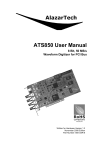
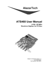
ATS310 User Manual
12 Bit, 20 MS/s
Waveform Digitizer for PCI Bus
Written for Hardware Version 1.2
October 2007 Edition
Part Number: 310-USR-2
Copyright © 2003-2007 AlazarTech. All rights reserved.
AlazarTech Contact Information
AlazarTech, Inc.
3551 St-Charles, Unit 640
Kirkland, Quebec
Canada H9H 3C4
Telephone: (514) 633-0001
Fax: (514) 633-0021
E-mail: [email protected]
Web site: www.alazartech.com
To comment on the documentation for ATS310, send e-mail to
[email protected].
Information required when contacting AlazarTech for technical support:
Owned by:
___________________________
Serial Number:
___________________________
Purchase Date:
___________________________
Purchased From:
___________________________
Software Driver Version: ___________________________
SDK Version:
___________________________
AlazarDSO Version:
___________________________
Operating System:
___________________________
ATS310 User Manual
i
Important Information
Warranty
The ATS310 is warranted against defects in materials and workmanship for a period of
one year from the date of shipment, as evidenced by receipts or other documentation.
AlazarTech, Inc. will, at its option, repair or replace equipment that proves to be
defective during the warranty period. This warranty includes parts and labor.
The media on which you receive AlazarTech, Inc. software are warranted not to fail to
execute programming instructions, due to defects in materials and workmanship, for a
period of 90 days from date of shipment, as evidenced by receipts or other
documentation. AlazarTech, Inc. will, at its option, repair or replace software media that
do not execute programming instructions if AlazarTech, Inc. receives notice of such
defects during the warranty period. AlazarTech, Inc. does not warrant that the operation
of the software shall be uninterrupted or error free.
A Return Material Authorization (RMA) number must be obtained from the factory and
clearly marked on the outside of the package before any equipment will be accepted for
warranty work. AlazarTech, Inc. will pay the shipping costs of returning to the owner
parts that are covered by warranty.
AlazarTech, Inc. believes that the information in this document is accurate. The
document has been carefully reviewed for technical accuracy. In the event that
technical or typographical errors exist, AlazarTech, Inc. reserves the right to make
changes to subsequent editions of this document without prior notice to holders of this
edition. AlazarTech, Inc. may also make improvements and/or changes in the products
and/or programs described in this document at any time. The reader should consult
AlazarTech, Inc. if errors are suspected. In no event shall AlazarTech, Inc. be liable for
any damages arising out of or related to this document or the information contained in
it. The latest user manual can be found on the AlazarTech, Inc. web page at
www.alazartech.com/support/downloads.htm.
EXCEPT AS SPECIFIED HEREIN, ALAZARTECH, INC. MAKES NO WARRANTIES,
EXPRESS OR IMPLIED, AND SPECIFICALLY DISCLAIMS ANY WARRANTY OF
MERCHANTABILITY OR FITNESS FOR A PARTICULAR PURPOSE. CUSTOMER’S
RIGHT TO RECOVER DAMAGES CAUSED BY FAULT OR NEGLIGENCE ON THE
PART OF ALAZARTECH, INC. SHALL BE LIMITED TO THE AMOUNT
THERETOFORE PAID BY THE CUSTOMER. ALAZARTECH, INC. WILL NOT BE
LIABLE FOR DAMAGES RESULTING FROM LOSS OF DATA, PROFITS, USE OF
PRODUCTS, OR INCIDENTAL OR CONSEQUENTIAL DAMAGES, EVEN IF ADVISED
OF THE POSSIBILITY THEREOF. This limitation of the liability of AlazarTech, Inc. will
apply regardless of the form of action, whether in contract or tort, including negligence.
Any action against AlazarTech, Inc. must be brought within one year after the cause of
action accrues. AlazarTech, Inc. shall not be liable for any delay in performance due to
causes beyond its reasonable control. The warranty provided herein does not cover
damages, defects, malfunctions, or service failures caused by owner’s failure to follow
the AlazarTech, Inc. installation, operation, or maintenance instructions; owner’s
modification of the product; owner’s abuse, misuse, or negligent acts; and power failure
or surges, fire, flood, accident, actions of third parties, or other events outside
reasonable control.
Copyright
Under the copyright laws, this publication may not be reproduced or transmitted in any
form, electronic or mechanical, including photocopying, recording, storing in an
information retrieval system, or translating, in whole or in part, without the prior written
consent of AlazarTech, Inc.
Trademarks
AlazarTech, Inc.™, AlazarTech™, alazartech.com™, ATS™, ATS310™, AlazarDSO™,
are trademarks of AlazarTech, Inc. Product and company names mentioned herein are
trademarks or trade names of their respective companies.
ii
ATS310 User Manual
Warning Regarding Use of AlazarTech Products
1.
ALAZARTECH, INC. PRODUCTS ARE NOT DESIGNED WITH COMPONENTS
AND TESTING FOR A LEVEL OF RELIABILITY SUITABLE FOR USE IN OR IN
CONNECTION WITH SURGICAL IMPLANTS OR AS CRITICAL COMPONENTS
IN ANY LIFE SUPPORT SYSTEMS WHOSE FAILURE TO PERFORM CAN
REASONABLY BE EXPECTED TO CAUSE SIGNIFICANT INJURY TO A
HUMAN.
2.
IN ANY APPLICATION, INCLUDING THE ABOVE, RELIABILITY OF
OPERATION OF THE SOFTWARE PRODUCTS CAN BE IMPAIRED BY
ADVERSE FACTORS, INCLUDING BUT NOT LIMITED TO FLUCTUATIONS IN
ELECTRICAL POWER SUPPLY, COMPUTER HARDWARE MALFUNCTIONS,
COMPUTER OPERATING SYSTEM SOFTWARE FITNESS, FITNESS OF
COMPILERS AND DEVELOPMENT SOFTWARE USED TO DEVELOP AN
APPLICATION, INSTALLATION ERRORS, SOFTWARE AND HARDWARE
COMPATIBILITY PROBLEMS, MALFUNCTIONS OR FAILURES OF
ELECTRONIC MONITORING OR CONTROL DEVICES, TRANSIENT FAILURES
OF ELECTRONIC SYSTEMS (HARDWARE AND/OR SOFTWARE),
UNANTICIPATED USES OR MISUSES, OR ERRORS ON THE PART OF THE
USER OR APPLICATIONS DESIGNER (ADVERSE FACTORS SUCH AS THESE
ARE HEREAFTER COLLECTIVELY TERMED “SYSTEM FAILURES”). ANY
APPLICATION WHERE A SYSTEM FAILURE WOULD CREATE A RISK OF
HARM TO PROPERTY OR PERSONS (INCLUDING THE RISK OF BODILY
INJURY AND DEATH) SHOULD NOT BE RELIANT SOLELY UPON ONE FORM
OF ELECTRONIC SYSTEM DUE TO THE RISK OF SYSTEM FAILURE. TO
AVOID DAMAGE, INJURY, OR DEATH, THE USER OR APPLICATION
DESIGNER MUST TAKE REASONABLY PRUDENT STEPS TO PROTECT
AGAINST SYSTEM FAILURES, INCLUDING BUT NOT LIMITED TO BACK-UP
OR SHUT DOWN MECHANISMS. BECAUSE EACH END-USER SYSTEM IS
CUSTOMIZED AND DIFFERS FROM ALAZARTECH, INC.’s TESTING
PLATFORMS AND BECAUSE A USER OR APPLICATION DESIGNER MAY
USE ALAZARTECH, INC. PRODUCTS IN COMBINATION WITH OTHER
PRODUCTS IN A MANNER NOT EVALUATED OR CONTEMPLATED BY
ALAZARTECH, INC., THE USER OR APPLICATION DESIGNER IS
ULTIMATELY RESPONSIBLE FOR VERIFYING AND VALIDATING THE
SUITABILITY OF ALAZARTECH INC. PRODUCTS WHENEVER ALAZARTECH,
INC. PRODUCTS ARE INCORPORATED IN A SYSTEM OR APPLICATION,
INCLUDING, WITHOUT LIMITATION, THE APPROPRIATE DESIGN, PROCESS
AND SAFETY LEVEL OF SUCH SYSTEM OR APPLICATION.
ATS310 User Manual
iii
Compliance
FCC/Canada Radio Frequency Interference Compliance*
Determining FCC Class
The Federal Communications Commission (FCC) has rules to protect wireless
communications from interference. The FCC places digital electronics into two classes.
These classes are known as Class A (for use in industrial-commercial locations only) or
Class B (for use in residential or commercial locations). Depending on where it is
operated, this product could be subject to restrictions in the FCC rules. (In Canada, the
Department of communications (DOC), of Industry Canada, regulates wireless
interference in much the same way.)
Digital electronics emit weak signals during normal operation that can affect radio,
television, or other wireless products. By examining the product you purchased, you can
determine the FCC Class and therefore which of the two FCC/DOC Warnings apply in
the following sections. (Some products may not be labeled at all for FCC; if so, the
reader should then assume these are Class A devices.)
FCC Class A products only display a simple warning statement of one paragraph in
length regarding interference and undesired operation. Most of our products are FCC
Class A. The FCC rules have restrictions regarding the locations where FCC Class A
products can be operated.
FCC Class B products display either a FCC ID code, starting with the letters EXN, or
the FCC Class B compliance mark.
Consult the FCC web site http://www.fcc.gov for more information.
FCC/DOC Warnings
This equipment generates and uses radio frequency energy and, if not installed and
used in strict accordance with the instructions in this manual and the CE Mark
Declaration of Conformity**, may cause interference to radio and television reception.
Classification requirements are the same for the Federal Communications Commission
(FCC) and the Canadian Department of Communications (DOC).
Changes or modifications not expressly approved by AlazarTech Inc. could void the
user’s authority to operate the equipment under the FCC Rules.
Class A
Federal Communications Commission
This equipment has been tested and found to comply with the limits for a Class A digital
device, pursuant to part 15 of the FCC Rules. These limits are designed to provide
reasonable protection against harmful interference when the equipment is operated in a
commercial environment. This equipment generates, uses, and can radiate radio
frequency energy and, if not installed and used in accordance with the instruction
manual, may cause harmful interference to radio communications. Operation of this
equipment in a residential area is likely to cause harmful interference in which case the
user will be required to correct the interference at his own expense.
Canadian Department of Communications
This Class A digital apparatus meets all requirements of the Canadian InterferenceCausing Equipment Regulations. Cet appareil numérique de la classe A respecte
toutes les exigences du Règlement sur le matériel brouilleur du Canada.
iv
ATS310 User Manual
Compliance to EU Directives
Readers in the European Union (EU) must refer to the Manufacturer's Declaration of
Conformity (DoC) for information** pertaining to the CE Mark compliance scheme. The
Manufacturer includes a DoC for most every hardware product except for those bought
for OEMs, if also available from an original manufacturer that also markets in the EU, or
where compliance is not required as for electrically benign apparatus or cables.
To obtain the DoC for this product, click Declaration of Conformity at
http://www.alazartech.com/support/documents.htm. This web page lists all DoCs by
product family. Select the appropriate product to download or read the DoC.
*
Certain exemptions may apply in the USA, see FCC Rules §15.103 Exempted
devices, and §15.105(c). Also available in sections of CFR 47.
**
The CE Mark Declaration of Conformity will contain important supplementary
information and instructions for the user or installer.
Environmental Compliance
Alazar Technologies Inc., hereby certifies that this product is RoHS compliant, as
defined by Directive 2002/95/EC of the European Parliament and of the Council of 27
January 2003 on the restriction of the use of certain hazardous substances in electrical
and electronic equipment. All manufacturing has been done using RoHS-compliant
components and lead-free soldering.
ATS310 User Manual
v
Table of Contents
CHAPTER 1 - INTRODUCTION ..................................................1
About Your ATS310 .....................................................................2
Acquiring Data with Your ATS310................................................3
Interactively Controlling your ATS310 with AlazarDSO ...........4
ATS-SDK API ...........................................................................5
ATS-VI LabVIEW VI..................................................................5
ATS-Linux .................................................................................6
Optional Upgrades .......................................................................7
CHAPTER 2 - INSTALLATION AND CONFIGURATION...........8
What You Need to Get Started ....................................................9
Unpacking ..................................................................................11
Installing the ATS310 .................................................................12
Installing the ATS310 in a Linux System....................................25
Compiling the ATS310 Linux Driver ...........................................26
Configuring Internet Security and Virus Protection Software to
Allow Proper Operation of ATS Class Digitizers ........................27
Updating ATS310 Driver ............................................................29
CHAPTER 3 - HARDWARE OVERVIEW..................................31
Input Connectors ........................................................................32
Signal Connections ....................................................................33
Analog Input ...............................................................................34
Pipelined ADC ........................................................................35
Pre-Trigger Multiple Record Acquisition.................................35
Specifying Record Length ......................................................35
Specifying Pretrigger Depth....................................................36
Specifying Record Count........................................................36
Calibration ..................................................................................37
Master/Slave Operation..............................................................38
Restrictions .............................................................................39
Optional Trigger Out Upgrade....................................................41
APPENDIX A - SPECIFICATIONS............................................43
vi
ATS310 User Manual
Chapter 1 - Introduction
This chapter describes the ATS310 and lists additional
equipment.
ATS310 User Manual
1
About Your ATS310
Thank you for your purchase of an ATS310. The ATS310 PCI
based waveform digitizer has the following features:
•
Two 12-bit resolution analog input channels
•
Half length PCI bus card
•
Real-time sampling rate of 20 MS/s to 10 KS/s
•
10 MHz analog input bandwidth
•
Analog trigger channel with software-selectable level,
slope, and hysteresis
•
Software-selectable AC/DC coupling and 1MΩ/50Ω
input impedance
•
128,000 sample onboard memory, standard
•
Pre-trigger and Post-Trigger Capture with Multiple
Record capability
•
NIST traceable calibration
All ATS310 digitizers follow industry-standard Plug and Play
specifications on all platforms and offer seamless integration
with compliant systems. If your application requires more
than two channels for data acquisition, you can synchronize
multiple digitizers on all platforms using a Master/Slave
SyncBoard.
Detailed specifications of the ATS310 digitizers are listed in
Appendix A, Specifications.
2
ATS310 User Manual
Acquiring Data with Your ATS310
You can acquire data either programmatically by writing an
application for your ATS310 or interactively with the
AlazarDSO software.
If you want to integrate the ATS310 in your test and
measurement or embedded OEM application, you can
program the digitizer using C/C++, Visual BASIC or
LabVIEW.
For programming in C/C++ or Visual BASIC, you must
purchase the ATS-SDK software development kit that comes
with sample programs and a reference manual describing the
API.
For programming in LabVIEW, you must purchase the ATSVI virtual instrument library that comes with a high-level,
easy-to-use VI that makes integrating the ATS310 into your
own system very simple.
ATS310 User Manual
3
Interactively Controlling your ATS310 with AlazarDSO
The AlazarDSO Soft Front Panel allows you to interactively
control your ATS310 as you would a desktop oscilloscope. To
launch the Scope Soft Front Panel, select
Start » Programs » AlazarTech » AlazarDSO
The following screen will be displayed. If you connect the
input to a signal generator and click on Start button, you
should see the signal on the screen.
AlazarDSO has been designed to be very intuitive and uses
the same user interface as most of today’s digital
oscilloscopes.
•
4
Note that AlazarDSO does not support Windows 98.
If you are using Windows 98SE, you can use the
legacy API Panel software for acquiring signals
interactively.
ATS310 User Manual
ATS-SDK API
The ATS-SDK API is used for programming the ATS310 in
C/C++ or Visual BASIC. It provides the exact same API that
is used for writing AlazarDSO software. To help you get
started, ATS-SDK comes with examples you can use or
modify.
ATS-VI LabVIEW VI
ATS-VI allows you to integrate the ATS310 into your own
LabVIEW program. A high level VI is supplied that requires
very few controls to get started.
ATS310 User Manual
5
ATS-Linux
ATS-Linux allows you to integrate the ATS310 into a Linux
application written in C. Linux drivers are provided as a
binary file, whereas all sample programs are supplied in C
source code. Compatible with kernel versions up to and
including 2.6.
6
ATS310 User Manual
Optional Upgrades
AlazarTech offers the following upgrades and accessories for
use with your ATS310 digitizer:
•
ATS310: External Clock Upgrade
•
ATS310: Trigger Output Upgrade
•
ATS310: Master/Slave SyncBoard
2 position
•
ATS310: Master/Slave SyncBoard
4 position
•
ATS310: Master/Slave SyncBoard
8 position
ATS310 User Manual
7
Chapter 2 - Installation
and Configuration
This chapter describes how to unpack, install, and configure
your ATS310.
8
ATS310 User Manual
What You Need to Get Started
To set up and use your ATS310, you will need the following:
•
One or more ATS310 digitizers
•
ATS310 Install Disk
•
For Master/Slave operation only:
SyncBoard of appropriate width
SyncBoard 2X for up to 2 digitizers
ATS310 User Manual
9
SyncBoard 4X for up to 4 digitizers
SyncBoard 8X for up to 8 digitizers
10
ATS310 User Manual
Unpacking
Your digitizer is shipped in an antistatic package to prevent
electrostatic damage to the digitizer. Electrostatic discharge
can damage several components on the digitizer. To avoid
such damage in handling the digitizer, take the following
precautions:
•
Ground yourself via a grounding strap or by holding a
grounded object.
•
Touch the antistatic package to a metal part of your
computer chassis before removing the digitizer from
the package.
•
Remove the digitizer from the package and inspect
the digitizer for loose components or any other sign
of damage. Notify AlazarTech if the digitizer appears
damaged in any way. Do not install a damaged
digitizer into your computer.
•
Never touch the exposed pins of the connectors.
ATS310 User Manual
11
Installing the ATS310
There are four main steps involved in installation:
1. Physically install the digitizer(s) and SyncBoard, if
any, in your computer
2. Install ATS310 software driver, when prompted
3. Install AlazarDSO software that allows you to setup
the hardware, acquire signals and view and archive
them
4. Optionally, install the ATS-SDK software
development kit or ATS-VI LabVIEW VI, which
enables you to programmatically control the ATS310
The following paragraphs will guide you through this process
in a step-by-step manner.
12
ATS310 User Manual
1. Physically install the digitizer in your computer
Make sure that your computer is powered off before
you attempt to insert the ATS310 digitizer in one of
the free PCI slots.
For best noise performance, leave as much room as
possible between your ATS310 and other hardware.
Always screw the digitizer bracket to the chassis in
order to create a stable and robust connection to
chassis ground.
In the absence of such a connection, ATS310 is not
guaranteed to operate within the specifications listed
elsewhere in this manual.
ATS310 User Manual
13
For Master/Slave Installation
If you are installing multiple ATS310 digitizers that
will be configured as a Master/Slave system, make
sure that you insert all cards in adjacent slots.
The connector on the SyncBoard that is labeled as
“M” (Master), must be inserted into the Master/Slave
connector of the left-most digitizer, if you are facing
the BNC connectors of the ATS310 digitizers.
14
ATS310 User Manual
If you are installing fewer than the maximum number
of digitizers supported by your SyncBoard, the
unused SyncBoard connectors must be on the righthand side of the digitizers, if you are facing the BNC
connectors of the ATS310 digitizers.
Zoomed in, this should look as shown below:
Once you have completed this step, you should
power the computer on.
ATS310 User Manual
15
2. Install ATS310 software driver, when prompted
The following instructions guide you through the
process of installing the ATS310 in a computer
running Windows XP, Windows 2000 or Windows
98SE operating systems. Other operating systems,
such as Windows NT, are not covered here.
Installation of Multiple ATS310 Digitizers
If you are installing multiple ATS310 digitizers, the
operating system will detect one card at a time and
you will have to go through the driver installation
setup as many times as you have cards.
If you are installing multiple ATS310 digitizers under
Windows 98SE, you will be prompted to reboot the
computer after each installation. You should only
reboot the computer after having installed the last
ATS310 digitizer.
16
ATS310 User Manual
Installing ATS310 Driver In Windows 98SE
When you first plug in an ATS310 digitizer into a
computer, the plug-n-play Windows 98SE operating
system will detect the presence of a new PCI card
and ask you to provide the device driver.
a) Operating System will display the Welcome to
the Found New Hardware Wizard
Click Next.
b) Operating system will display the Install
Hardware Device Driver dialog box
Select the radio button next to the text Display a
list of the known drivers for this device so that I
can choose a specific driver. Click Next.
c) Operating system will display the Hardware
Type dialog box
Select System devices
d) Operating system will display the Select a
Device Driver dialog box
Click on Have Disk
e) Operating system will display the Install from
Disk dialog box
Make sure the path points to D:\Win2K_98SE\,
or wherever the ATS310.INF file resides. If you
are using a floppy disk or a CD, make sure the
disk is inserted in the drive.
Select the ATS310.INF file and click Open
The operating system may display Install from
Disk dialog box again. If it does, Click OK,
otherwise continue to the next step
ATS310 User Manual
17
f)
Operating system will display the Select a
Device Driver dialog box again.
Make sure the AlazarTech ATS310 PCI
Digitizer is selected. Then click Next.
g) Operating system will display the Update Driver
Warning. This warning is meant to tell you that
Windows does not recognize the hardware.
Click Yes.
h) Operating system will display the Start Device
Driver Installation dialog box.
Click Next. System will copy all necessary files
to the appropriate folders.
i)
Operating system will display the Completing
the Found New Hardware Wizard message.
Click Finish.
18
ATS310 User Manual
Installing ATS310 Driver in Windows 2000
Before proceeding, make sure that you have
sufficient administrative rights to install device drivers
on your computer. Typically, you should be the
Administrator for the computer you are installing
device drivers on.
When you first plug in an ATS310 digitizer into a
computer, the plug-n-play Windows 2000 operating
system will detect the presence of a new PCI card
and ask you to provide the device driver.
a) Operating System will display the Welcome to the
Found New Hardware Wizard
Click Next.
b) Operating system will display the Install Hardware
Device Driver dialog box
Select the radio button next to the text Display a list
of the known drivers for this device so that I can
choose a specific driver. Click Next.
c) Operating system will display the Hardware Type
dialog box
Select System devices
d) Operating system will display the Select a Device
Driver dialog box
Click on Have Disk
e) Operating system will display the Install from Disk
dialog box
Make sure the path points to D:\Win2K_98SE\, or
wherever the ATS310.INF file resides. If you are
using a floppy disk or a CD, make sure the disk is
inserted in the appropriate drive.
ATS310 User Manual
19
f)
Select the ATS310.INF file and click Open
The operating system may display Install from Disk
dialog box again. If it does, Click OK, otherwise
continue to the next step
g) Operating system will display the Select a Device
Driver dialog box again.
Make sure the AlazarTech ATS310 PCI Digitizer is
selected. Then click Next.
h) Operating system will display the Update Driver
Warning. This warning is meant to tell you that
Windows does not recognize the hardware.
Click Yes.
i)
Operating system will display the Start Device
Driver Installation dialog box.
Click Next. System will copy all necessary files to
the appropriate folders.
j)
Operating system will display the Completing the
Found New Hardware Wizard message.
Click Finish.
20
ATS310 User Manual
Installing ATS310 Driver In Windows XP
ATS310 Install Disk is fully compatible with both 32-bit and
64-bit versions of Windows XP and Windows Vista.
Before proceeding, make sure that you have sufficient
administrative rights to install device drivers on your
computer. Typically, you should be the Administrator for the
computer you are installing device drivers on.
When you first plug in an ATS310 digitizer into a computer,
the plug-n-play Windows XP operating system will detect the
presence of a new PCI card and ask you to provide the
device driver.
a) Operating System will display the Welcome to the
Found New Hardware Wizard
Click on the radio button next to the text Install from a
list or specific location (Advanced).
Click Next.
b) Operating System will display the Please choose
your search and installation options dialog box.
Click on the radio button next to the text Don’t
search. I will choose the driver to install.
Click Next.
c) Operating system will display the Hardware Type
dialog box
Select System devices
d) Operating system will display the Select the device
driver you want to install for this hardware dialog
box
Click on Have Disk
ATS310 User Manual
21
e) Operating system will display the Install from Disk
dialog box
Make sure the path points to D:\, or wherever the
ATS310.INF file resides. If you are using a floppy
disk or a CD, make sure the disk is inserted in the
drive.
Click OK.
f)
Operating system will display the Select the device
driver you want to install for this hardware dialog
box again.
Make sure the AlazarTech ATS310 PCI Digitizer is
selected (highlighted).
Click Next.
g) Operating system will display the Update Driver
Warning. This warning is meant to tell you that
Windows does not recognize the hardware.
Click Yes.
h) System will copy all necessary files to the appropriate
folders.
i)
Operating system will display the Completing the
Found New Hardware Wizard message.
Click Finish.
22
ATS310 User Manual
3. Install AlazarDSO software that allows you to
setup the hardware, acquire signals and view and
archive them
If you are installing from the CD shipped with the
ATS310 digitizer:
•
Insert the ATS310 Install disk
•
Use Windows Explorer to navigate to the
appropriate AlazarDSO folder on the ATS310
Install Disk. Run Setup.exe program.
•
Note that AlazarDSO is available in two
versions: 32-bit and 64-bit. Please install the
version appropriate for your operating
system.
•
Follow the instructions on the screen.
If you are installing AlazarDSO after having
downloaded the installation file from AlazarTech web
site:
•
Download AlazarDSO installation file from
www.alazartech.com/support/downloads.htm
•
Unzip the file downloaded in the previous
step.
•
Browse to the folder that contains the
unzipped file, Setup.exe
•
Run this executable file and follow the
instructions on the screen.
ATS310 User Manual
23
4. Optionally, install the ATS-SDK software
development kit or ATS-VI LabVIEW VI, which
enables you to programmatically control the
ATS310
Insert the ATS-SDK or ATS-VI CD. Software
installation will start automatically.
If, for any reason, installation does not start
automatically, run the SETUP.EXE program.
Follow the instructions on the screen.
Note that you must have already installed the
ATS310 drivers for any of the sample programs
included with the ATS-SDK or ATS-VI to work
properly.
24
ATS310 User Manual
Installing the ATS310 in a Linux System
ATS310 is fully compatible with the popular Linux operating
system.
AlazarTech supplies binary Linux drivers that have been
compiled for Fedora Core 5 (kernel 2.6).
Customers who require drivers for another version of Linux
must contact the factory to obtain source code for the drivers
(requires a Non-Disclosure Agreement). AlazarTech will not
provide software support for compiling drivers for other
versions of Linux, i.e. customers will be fully responsible for
compiling drivers for their own Linux operating system.
To install Linux drivers in a Fedora Core 5 system, follow the
instructions listed below:
1. Copy the supplied RPM file to the target machine
2. Double-click on the RPM icon. This will install the
driver as well as associated applications.
3. Reboot the PC.
Note that if you do not reboot the PC, the driver will
not be loaded.
The RPM file will also install an application called AlazarDSO.
This is a Graphical User Interface (GUI) using which you can
setup and acquire data from the ATS310.
Note that AlazarDSO has been compiled using GTK 2.4
libraries. If you intend to use an operating system other
than Fedora Core 5, make sure that the GTK 2.4 libraries
have been installed on your machine.
ATS310 User Manual
25
Compiling the ATS310 Linux Driver
If you need to compile the ATS310 driver for a version of
Linux other than Fedora Core 5, follow the following steps:
1. Install the Linux kernel header files.
2. Extract the driver sources using the command "tar
xvfz PlxLinux-2006.01.10.tgz". This will create a
folder names "PlxLinux" with the driver files inside.
3. Set the shell environment variable PLX_SDK_DIR to
the root location where the "PlxLinux" directory was
created. For example, if using bash and the PlxLinux
directory is in your home directory, then add the
following line to the ~/.bashrc :
declare -x PLX_SDK_DIR=$HOME/PlxLinux
4. To build the ATS310 driver, type
cd PlxLinux/linux/driver
./builddriver 310
This will create the file Pci9054/ATS310.ko, the
loadable driver file. You can change build defines in
PlxLinux/linux/makefiles/Gcc.def. Copy the driver to
/usr/local/AlazarTech/bin.
5. Load the driver by rebooting the computer or typing:
cd /usr/local/AlazarTech/bin
ATS310.rc start
The customer should be able to run the AlazarDSO
application or Acq2Disk sample in
/usr/local/AlazarTech/samples/ATS310.
6. If it is necessary to rebuild the library, type
cd PlxLinux/linux/api
make
This will create SharedLibrary/libPlxApi.so.0.0. Copy the file
to /usr/local/AlazarTech/lib and then run ldconf
26
ATS310 User Manual
Configuring Internet Security and Virus
Protection Software to Allow Proper
Operation of ATS Class Digitizers
Some of the recent releases of internet security and virus
protection software packages, such as Norton Anti-Virus,
disable any unused parallel or serial ports as well as any PCI
devices that have not been assigned to a software application
by the user. Users of AlazarTech PCI digitizers must
configure their security software to allow access to the PCI
digitizers.
The problem exhibits itself as a blue-screen crash and a
“STOP Error”.
Typically, this error message is:
STOP:
0x0000000A
(0x00000016, 0x0000001C, 0x00000000, 0x804E5DEB)
For more details on this problem with anti-virus software
packages, refer to the technical note on Microsoft’s support
site :
http://support.microsoft.com/kb/892000/EN-US
Also refer to the knowledgebase article on Symantec’s web
site:
http://service1.symantec.com/SUPPORT/sharedtech.nsf/0/26
71ef6e5d72d3cd88256d26006699d5?OpenDocument
This article explains that the root of the problem is one of the
files updated by the Symantec anti-virus software.
Symantec suggests that users should upgrade their internet
security software using Live Update, but our customers’
experience has been that this does not always work.
ATS310 User Manual
27
The solution that always works is:
•
Remove Norton Anti-Virus software
•
Reboot the PC after removing Norton Anti-Virus.
•
Make sure AlazarTech hardware and software are
fully functional
•
Re-install Norton Anti-Virus software
AlazarTech PCI digitizer products are fully compatible with all
internet security and anti-virus software. Users must make
sure that their security software has been updated and
configured properly.
28
ATS310 User Manual
Updating ATS310 Driver
From time to time, AlazarTech updates the device drivers for
its products. These updates may be required for product
enhancements or for bug fixes.
This section of the manual takes you through the steps
required to update the device driver for the ATS310 PCI
digitizer.
In other words, this section shows you how to install a newer
version of the driver, when you already have a previous
version of the driver installed on your machine.
1. Run Device Manager. To do so:
a. Run Control Panel by opening
Start » Settings » Control Panel
b. Open System Properties dialog box by
selecting or double-clicking on the System
menu
c.
Click on Hardware tab in the dialog box
d. Click on Device Manager button
2. Device Manager lists all hardware devices in your
computer.
a. For Windows 2000 and Windows 98SE,
AlazarTech PCI digitizers are listed within
System Devices.
b. For Windows XP and Windows Vista,
AlazarTech PCI digitizers are listed in their
own class called AlazarTech PCI Digitizers
3. Expand the appropriate device list.
a. For Windows 2000 and Windows 98SE,
expand the System Devices list.
b. For Windows XP and Windows Vista, expand
the AlazarTech PCI Digitizers list.
ATS310 User Manual
29
4. Double-click on the ATS310 device:
a. For Windows 2000 and Windows 98SE,
double-click on AlazarTech ATS310 PCI
Digitizer device.
b. For Windows XP and Windows Vista,
double-click on the ATS310: 12-bit, 20 MS/s,
2 ch PCI Digitizer
c.
If more than one such devices are present,
choose the first one in the list
5. This will open up the ATS310 Properties page
6. Click on the Driver tab
7. Click on Update Driver button near the bottom-right
corner of the page
8. This will cause the Upgrade Device Driver Wizard
to be started
9. To complete the installation, follow the instructions
provided in the section labeled:
a. Installing ATS310 Driver in Windows 98SE
Or
b. Installing ATS310 Driver in Windows 2000
Or
c.
30
Installing ATS310 Driver in Windows XP and
Vista
ATS310 User Manual
Chapter 3 - Hardware
Overview
This chapter includes an overview of the ATS310, explains
the operation of each functional unit making up your ATS310,
and describes the signal connections. Following is a highlevel block diagram of ATS310.
CH A
Analog
Front-End
A
D
C
ASoPC
CH B
Analog
Front-End
A
D
C
Acquisition
System
On
Programmable
EXT Trig
Analog
Front-End
Trigger
Circuit
Chip
(FPGA)
EXT Clock
Input
Protection
P
C
I
B
U
S
ATS310 User Manual
Memory
PCI Bus
Interface
ASIC
31
Input Connectors
These ATS310 digitizers have two standard BNC female
connectors for CH A and CH B analog input connections, one
standard BNC female connector for the EXT (External
Trigger) input and one standard BNC female connector for
the optional ECLK (External Clock) input or optional TRIG
OUT output.
For applications that require both External Clock Input and
TRIG OUT output, contact the factory for special cabling.
The following pictorial shows the various connectors available
on the digitizer bracket.
Identification LED
For future use
Channel A
Channel B
External Trigger
Optional External Clock input
Or
Optional TRIG OUT output
32
ATS310 User Manual
Signal Connections
You can use CH A and CH B to digitize data as well as to
trigger an acquisition.
Use the EXT input for an external analog trigger only; data on
the TRIG channel cannot be digitized.
If External Clock Upgrade is installed on your ATS310, use
the ECLK input for clocking the ATS310 in applications that
require an external clock. Note that the frequency of the
signal injected into the ECLK connector must remain between
20 MS/s and 1 MS/s.
If Trigger Output Upgrade is installed on your digitizer, ECLK
connector can be used for outputting TRIG OUT signal, a 5 V
TTL signal synchronous with the on-board trigger signal and
the sampling clock.
ATS310 User Manual
33
Analog Input
The two analog input channels are referenced to common
ground in bipolar mode. These settings are fixed; therefore,
neither the reference nor the polarity of input channels can be
changed. You cannot use CH A or CH B to make differential
measurements or measure floating signals unless you
subtract the digital waveforms in software.
For accurate measurements, make sure the signal being
measured is referenced to the same ground as your ATS310
by attaching the probe’s ground clip to the signal ground.
The EXTernal Trigger input has a programmable input range
of ±5 V or ±1 V.
The CH A, CH B, and EXT inputs have a softwareprogrammable coupling selection between AC and DC. Use
AC coupling when your AC signal contains a large DC
component. Without AC coupling, it is difficult to view details
of the AC component with a large DC offset and a small AC
component, such as switching noise on a DC supply. If you
enable AC coupling, you remove the large DC offset for the
input amplifier and amplify only the AC component. This
technique makes effective use of dynamic range to digitize
the signal of interest.
The low-frequency corner in an AC-coupled circuit is the
frequency below which signals are attenuated by at least 3
dB. The low-frequency corner is approximately 10 Hz with 1
MΩ input impedance and 100 KHz with 50Ω input
impedance.
34
ATS310 User Manual
Pipelined ADC
The ADC on the ATS310 is a pipelined flash converter with a
maximum conversion rate of 20 MS/s.
If you use an external clock, you must provide a free-running
clock to ensure reliable operation. You also must follow all
the timing specifications on the external clock as described in
Appendix A, Specifications.
Using a pipelined architecture also introduces a lower limit on
the sampling rate. For the ATS310, the accuracy starts to
degrade below 1 MS/s.
Pre-Trigger Multiple Record Acquisition
The ATS310 allows the capture of multiple records into the
on-board memory. This allows you to capture rapidly
occurring triggers in lightning test, ultrasound or radar
applications.
Unlike other digitizers on the market, users are allowed to
acquire both pre- and post-trigger data when acquiring more
than one record in an acquisition session. This feature can
be very useful in lightning test, power line monitoring and
other applications that feature rapidly occurring transient
signals.
Specifying Record Length
Record Length is specified in number of sample points. It
must be a minimum of 64 points and can be specified with a
4-sample resolution up to a maximum of the per-channel onboard memory.
Record Length thus specified determines the maximum
number of records you can capture in one acquisition
session. The relationship is given by:
Max. Records = (Per-Channel Memory) / (Record Length + 4)
Note that, unlike other products in its class, ATS310 allows
you to capture multiple records into the on-board memory
without requiring software-assisted re-arming of the digitizer.
ATS310 User Manual
35
Specifying Pretrigger Depth
ATS310 acquires a certain number of samples, called the
pretrigger depth, before it allows the trigger circuitry to
operate, thereby guaranteeing that the required number of
sample points will be captured before trigger occurs.
User is allowed to set pretrigger depth for an acquisition
session. Same values are used for all records captured in
that session.
Pretrigger depth can be a minimum of 0 points and can be
specified with a 4 sample resolution up to a maximum of
(Record Length –64).
Specifying Record Count
User can specify the number of records that must be
captured in one acquisition session. The minimum value
must be 1 and the maximum value is given by:
Max. Records = (Per-Channel Memory) / (Record Length + 4)
36
ATS310 User Manual
Calibration
Calibration is the process of minimizing measurement errors
by making small circuit adjustments.
All ATS310 digitizers come factory calibrated to the levels
indicated in Appendix A, Specifications. Note that AlazarTech
calibration is fully NIST traceable.
However, your digitizer needs to be periodically recalibrated
in order to maintain its specified accuracy. This calibration
due date is listed on the CALIBRATION sticker affixed to your
ATS310 digitizer.
Externally recalibrate the ATS310 when this calibration
interval has expired.
This requires three very simple steps:
1. Verify whether or not ATS310 is still within its
specifications. If it is, then your calibration can be
extended by another one-year period
2. If not, perform calibration, i.e. make adjustments to
the circuit until it is within specifications again
3. If any adjustments have been made, verify if the
ATS310 is within specifications
Verification and Calibration procedures are available to all
registered users of ATS310 upon request.
ATS310 User Manual
37
Master/Slave Operation
You can use two or more ATS310 digitizers in one system to
increase the number of channels for your application by
synchronizing digitizers using the appropriate SyncBoard.
Currently, up to 16 channel (8 board) systems are supported
for ATS310. For higher channel counts, contact the factory
for special system configuration.
Unlike other products on the market, ATS310 does not suffer
from clock jitter between master and slave digitizers.
The unique design of the ATS310 clock circuit provides a
buffered copy of the Master digitizer’s clock to itself and all
the slave digitizers, thereby maintaining a very low skew
between Master and Slave digitizer clocks.
Note that an ATS310 Master/Slave system is capable of
triggering from any one of its input channels. This is valuable
in multi-channel detector applications that cannot predict the
input channel that is going to receive the first pulse.
With fully synchronous A/D conversion, arming and
triggering, an ATS310 based Master/Slave system is an ideal
multi-channel transient analyzer.
38
ATS310 User Manual
Restrictions
To ensure proper master/slave operation of your ATS310
digitizers, you must observe the following restrictions:
•
All Master/Slave digitizers must be installed in
adjacent slots, i.e. there should be no gap between
the digitizers that are to be configured as a
Master/Slave system
Good Installation
Bad Installation
•
You must connect the appropriate SyncBoard to all of
the ATS310 digitizers in your system. Note that all
SyncBoards are polarized, so you cannot make a
mistake in inserting them
•
If you are using fewer than the maximum number of
digitizers allowed by the SyncBoard, make sure that
the connector labeled “M” (Master) on the SyncBoard
is connected to one of the ATS310 digitizers. Any
over-hang of the SyncBoard should be beyond the
last slave board in your system
ATS310 User Manual
39
The presence of a SyncBoard is detected by the ATS310
driver when the ATSApi DLL is loaded. This DLL gets loaded
when you run any application program written for ATS310.
Examples of such application programs are AlazarDSO, one
of the sample programs supplied with ATS-SDK or ATS-VI or
any custom software written using ATS-SDK or ATS-VI.
If you run AlazarDSO or your own software that loads the
ATSApi DLL, after having installed a SyncBoard, the ATS310
driver will automatically recognize that the digitizers are now
configured as Master/Slave.
As such, there is no need to have your hardware upgraded or
modified in any way to go from a set of independent boards
to Master/Slave and vice-versa.
40
ATS310 User Manual
Optional Trigger Out Upgrade
Many ultrasound applications require the digitizer to generate
a Trigger Output signal synchronous with its internal sampling
clock.
Such synchronization is almost essential if multiple
acquisitions have to be averaged.
ATS310 uses a high quality crystal-controlled clock
oscillator as its timebase.
It should be noted that crystal oscillators are one of
the most reliable and repeatable types of clock
source available.
Crystal oscillators also provide far superior long-term
jitter performance compared to PLL based clocking
schemes.
The same qualities that make crystal oscillators such
an ideal clock source also make it impossible to
synchronize them to an external signal, such as an
external trigger input or a 10 MHz reference clock.
As such, the best way to fully synchronize the acquisition
system to a signal source, such as a pulser-receiver, is to
trigger the pulser-receiver with a trigger signal that has
already been synchronized to the ADC sampling clock.
Hence the Optional Trigger Out Upgrade.
ATS310 User Manual
41
TRIGGER FROM
MOTION SYSTEM
(EXT INPUT)
ATS310
PCI Digitizer
TRIGGER OUT
(TRIG OUT OUTPUT)
ECHO SIGNAL
(CHA INPUT)
PulserReceiver
ULTRASONIC
PROBE
When connected as shown in the diagram above, the system
works as follows:
CLOCK
TRIGGER
TRIG OUT
PULSER
OUTPUT
TRIGGER DELAY
ECHO
RECORD LENGTH
42
ATS310 User Manual
Appendix A Specifications
This appendix lists the specifications of the ATS310. These
specifications are typical at 25 °C unless otherwise stated.
The operating temperature range is 0 to 50 °C.
System Requirements
Pentium based computer with at least one free PCI slot, 128 MB RAM, 20
MB of free hard disk space, SVGA display adaptor and monitor with at least
an 800 x 600 resolution. API Panel requires Internet Explorer 5.0 or higher.
Power Requirements
+5V
1.5 A, typical
+5V voltage level must remain between the
range of 4.75V to 5.20V at all times after
power-on
Physical
Size
Single slot, half-length PCI card
(4.2 inches x 7.2 inches)
Weight
500 g
I/O Connectors
CH A, CH B, EXT, ECLK
BNC female connectors
Environmental
o
Operating temperature
0 to 55 C
Storage temperature
-20 to 70 C
Relative humidity
5 to 95%, non-condensing
o
Acquisition System
Resolution
12 bits
Bandwidth (-3dB)
DC-coupled, 1MΩ
DC - 10 MHz
DC-coupled, 50Ω
DC - 10 MHz
AC-coupled, 1MΩ
10 Hz - 10 MHz
AC-coupled, 50Ω
Bandwidth flatness:
ATS310 User Manual
100KHz - 10 MHz
± 1dB, from DC to 10 MHz with DC coupling
± 1dB, from 50Hz to 10 MHz with AC, 1 MΩ
± 1dB, from 200 KHz to 10 MHz with AC, 50Ω
43
Number of channels
2 simultaneously sampled
Maximum Sample Rate
20 MS/s single shot
Minimum Sample Rate
10 KS/s single shot (internal clock)
Full Scale Input ranges
±40mV, ±50mV, ±80mV, ±100mV, ±200mV,
±400mV, ±500mV, ±800mV, ±1V, ±2V, ±4V,
±5V, ±8V, ±10V and ±20V, software
selectable.
DC accuracy
±2% of full scale in all input ranges
Input coupling
AC or DC, software selectable
Input impedance
50Ω or 1MΩ ±1% in parallel with 30 pF ±10pF,
software selectable
Input protection
1MΩ
±28V (DC + peak AC for CH A,
CH B and EXT only without external
attenuation)
50Ω
±8V (DC + peak AC for CH A,
CH B and EXT only without external
attenuation)
Acquisition Memory System
Acquisition Memory/channel Up to 128,000 samples per channel standard,
or
Up to 8,000,000 samples per channel with
High Memory Option
Record Length
Software selectable with 4-point resolution.
Record length must be a minimum of 256
points. Maximum record length is limited by
the acquisition memory per channel.
Number of Records
Software selectable from a minimum of 1 to a
maximum of 1,000 or (Acquisition Memory Per
Channel / (Record Length+4)), whichever is
lower
Pre-trigger depth
0 to (Record Length-64), software selectable
with 4 point resolution
Post-trigger depth
Record Length - Pre-trigger depth
Timebase System
Timebase options
Internal Clock or
External Clock (Optional)
Internal Sample Rates
20 MS/s, 10 MS/s, 5 MS/s,
2 MS/s, 1 MS/s, 500 KS/s,
200 KS/s, 100KS/s, 50 KS/s,
20KS/s, 10KS/s
Internal Clock accuracy
±100 ppm
44
ATS310 User Manual
Dynamic Parameters
Typical values measured using a randomly selected ATS310 in ±1V input
range, DC coupling and 50Ω impedance. Input was provided by a HP8656A
signal generator, followed by a 9-pole, 1 MHz band-pass filter. Input
frequency was set at 1 MHz and amplitude was 650 mV rms (92% of full
scale input).
SNR
62 dB
SINAD
58 dB
THD
-61 dB
SFDR
-62 dB
Note that these dynamic parameters may vary from one unit to another, with
input frequency and with the full-scale input range selected.
Optional ECLK (External Clock) Input
Signal Level
TTL levels. Compatible with both 3.3V and 5V
TTL
Input impedance
50Ω
Input current requirement
±66mA
Maximum frequency
20 MHz with 50% ±5% duty cycle
Minimum frequency
1 MHz with 50% ±5% duty cycle
Decimation factor
Software selectable from 1 to 100,000
Sampling Edge
Rising or Falling,
software selectable
Triggering System
Mode
Edge triggering with fixed hysteresis
Number of Trigger Engines
2
Trigger Engine Combination
OR, AND, XOR, software selectable
Trigger Engine Source
CH A, CH B, EXT, Software or None,
independently software selectable for each of
the two Trigger Engines
Hysteresis
±5% of full-scale input, typical
Trigger sensitivity
±10% of full scale input range.
This implies that the trigger system may not
trigger reliably if the input has an amplitude
less than ±10% of full-scale input range
selected
Trigger level accuracy
±10%, typical, of full-scale input range of the
selected trigger source
Bandwidth
25 MHz
Trigger Delay
Software selectable from 0 to 9,999,999
sampling clock cycles
ATS310 User Manual
45
Trigger Timeout
Software selectable with a 10 us resolution.
Maximum settable value is 3,600 seconds.
Can also be disabled to wait indefinitely for a
trigger event
EXT (External Trigger) Input
Input impedance
1 MΩ in parallel with 30pF ±10pF
Bandwidth (-3dB)
DC-coupled
DC - 10 MHz
AC-coupled
10 Hz - 10 MHz
Input range
±5V or ±1V, software selectable
DC accuracy
±10% of full-scale input
Input protection
±28V (DC + peak AC without external
attenuation)
Coupling
AC or DC, software selectable
Certification and Compliances
CE Mark Compliance
Materials Supplied
One ATS310 Digitizer
One ATS310 Install Disk (CD)
One ATS310 User Manual
All specifications are subject to change without notice
46
ATS310 User Manual
ATS310 User Manual
47
48
ATS310 User Manual
ALAZAR TECHNOLOGIES INC.
3551 St-Charles, Unit 640
Kirkland, QC
CANADA H9H 3C4
Tel:
Fax:
(514) 633-0001
(514) 633-0021
E-mail:
Web:
[email protected]
www.alazartech.com