1
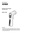
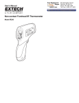
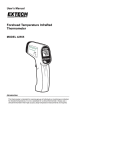
User’s Manual
Mini InfraRed Thermometer
with Laser Pointer
MODEL 42500
Introduction
Congratulations on your purchase of the Model 42500 IR Thermometer. This thermometer
makes non-contact (infrared) temperature measurements at the touch of a button. The
built-in laser pointer increases target accuracy while the backlit LCD and handy pushbuttons combine for convenient, ergonomic operation. Proper use and care of this meter
will provide years of reliable service.
Safety
•
Use extreme caution when the laser pointer beam is on
•
Do not point the beam toward anyone's eye or allow the
beam to strike the eye from a reflective surface
•
Do not use the laser near explosive gases or in other
potentially explosive areas
Specifications
Infrared Thermometer Specifications
o
o
o
Range / Resolution
-4 to 500 F (-20 to 260 C)
Accuracy
± 2% of reading or ± 4 F (2 C) whichever is greater, from 60
o
o
to 113 F (15 to 50 C)
1 C/F
o
o
o
o
± 3% of reading or ± 6 F (3 C) whichever is greater, for
o
o
remainder of range: -4 to 500 F (-20 to 260 C)
Note: Accuracy is specified for the following ambient
temperature range: 64 to 82°F (18 to 28°C)
Emissivity
0.95 fixed value
Field of View
D/S = Approx. 6:1 ratio (D = distance, S = spot)
Laser power
Less than 1mW
Spectral response
6 to 14 µm (wavelength)
General Specifications
Display
2000 count, backlit LCD display with function indicators
Display rate
1 second approx.
Operating Temperature
32°F to 122°F (0°C to 50°C)
Operating Humidity
Max. 80% RH
Power Supply
9V battery
Automatic Power Off
Meter shuts off automatically after 6 seconds
Weight
4.9 oz. / 140g
Dimensions
6.7 x 1.7 x 1.6” (170 x 44 x 40mm)
Meter Description
1.
LCD Display
2.
Function Buttons
3.
Handle Grip
4.
IR Sensor
5.
Laser pointer beam
6.
Measurement Trigger
7.
Battery Compartment
4
5
1
2
6
3
7
2
Model 42500 Version 1.4 March 2006
Operating Instructions
1. Hold the meter by its Handle Grip and point it toward the surface to be measured.
Read the Field of View section below for information on distance to target ratios.
2. Pull and hold the orange Trigger to turn the meter on and begin testing. The display will
light if the battery is good. Replace the battery if the display does not light.
3. While continuing to pull the Trigger:
a. Push the Laser button to turn on the laser pointer. When the laser is on, the laser
icon
will appear on the LCD over the temperature reading. Aim the red beam
approximately a half inch below the point of test (pressing the Laser button again
turns the laser off).
o
o
b. Select the temperature units using the C / F button.
c. Push the backlight button (far right) to turn on the LCD backlighting function.
4. Release the Trigger and the reading will hold for approximately 6 seconds and then the
meter will automatically shut off.
5. The meter defaults to the programmed conditions in use when the meter was last
o
turned off. For example, if the laser is set to ON and the temperature units are set to F
at the time the unit is turned off, the unit will turn on employing the same settings.
Over-range Indicator
If the temperature measurement exceeds 500°F (260°C), the thermometer will display
dashes in place of a temperature reading.
Field of View
The meter’s field of view is 6:1. For example, if the meter is 12 inches from the target
(spot), the diameter of the target must be at least 2 inches. Other distances are shown
below in the field of view diagram.
Note that measurements should normally be made less than 2 feet from the target. The
meter can measure from further distances but the measurement may be affected by
external sources of light. In addition, the spot size may be so large that it encompasses
surface areas not intended to be measured.
Diameter of Spot
0.5”
4”
2”
1”
Sensor Beam
0.63”
Laser Beam
3”
6”
12”
24”
Distance to Object
3
Model 42500 Version 1.4 March 2006
Measurement Notes
1. The object under test should be larger than the spot (target) size calculated by the field
of view diagram.
2. If the surface of the object under test is covered with frost, oil, grime, etc., clean before
taking measurements.
3. If an object's surface is highly reflective apply masking tape or flat black paint to the
surface before measuring.
4. The meter may not make accurate measurements through transparent surfaces such
as glass.
5. Steam, dust, smoke, etc. can obscure accurate measurements.
6. The meter compensates for deviations in ambient temperature. It can, however, take
up to 30 minutes for the meter to adjust to extremely wide ambient temperature
changes.
7. To find a hot spot, aim the meter outside the area of interest then scan across (in an up
and down motion) until the hot spot is located.
Battery Replacement
When the low battery symbol
appears on the LCD, replace the meter’s 9V battery.
The battery compartment is located on the bottom of the meter's handle. Open the
compartment by sliding the battery compartment cover off in the direction of the arrow.
Replace battery and re-install the battery compartment cover.
Calibration and Repair Services
Extech offers repair and calibration services for the products we sell. Extech also provides
NIST certification for most products. Call the Customer Service Department for information
on calibration services available for this product. Extech recommends that annual
calibrations be performed to verify meter performance and accuracy.
Support Hotline (781) 890-7440
Tech support: Ext. 200; Email: [email protected]
Repair/Returns: Ext. 210; Email: [email protected]
Website: www.extech.com
Warranty
EXTECH INSTRUMENTS CORPORATION warrants this instrument to be free of defects in parts and
workmanship for three (3) years from date of shipment (a six month limited warranty applies on sensors and
cables). If it should become necessary to return the instrument for service during or beyond the warranty
period, contact the Customer Service Department at (781) 890-7440 ext. 210 for authorization or visit our
website at www.extech.com (click on ‘Contact Extech’ and go to ‘Service Department’ to request an RA
number). A Return Authorization (RA) number must be issued before any product is returned to Extech. The
sender is responsible for shipping charges, freight, insurance and proper packaging to prevent damage in
transit. This warranty does not apply to defects resulting from action of the user such as misuse, improper
wiring, operation outside of specification, improper maintenance or repair, or unauthorized modification. Extech
specifically disclaims any implied warranties or merchantability or fitness for a specific purpose and will not be
liable for any direct, indirect, incidental or consequential damages. Extech's total liability is limited to repair or
replacement of the product. The warranty set forth above is inclusive and no other warranty, whether written or
oral, is expressed or implied.
Copyright © 2006 Extech Instruments Corporation.
All rights reserved including the right of reproduction in whole or in part in any form.
4
Model 42500 Version 1.4 March 2006