1
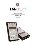
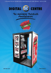
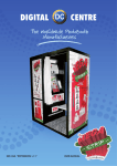
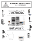
_______________________________
PROFESSIONAL TIMING
PRECISION TIME BASE - PTB 605
V3.3-E, 26 July 2000
USER’S MANUAL AND TECHNICAL DESCRIPTION
1. INTRODUCTION
2. TECHNICAL DESCRIPTION
3. ON and OFF MODES
4. SOFTWARE CONTROL ON FLOPPY DISK OR VIA MICROSOFT HYPER TERMINAL™
5. SYNCHRONISATION - “TOP” OF THE MINUTE
6. TIMING
7. NEW SESSION
8. MEMORY MANAGEMENT
9. CONTROL FUNCTIONS
10. ADJUSTING PARAMETERS
11. SERIAL DATA STRING FORMAT
12. PRINTER PORT INFORMATION
13. DISPLAY AND PRINTER PORT MESSAGES
14. SERIAL DATA OUTPUT STRING FORMATS
15. DB25 EXT. CONNECTOR PORT INFORMATION
16. EXT. POWER CONNECTOR
17. COMMAND MESSAGE SUMMARIES FOR COMPUTER
18.
TECHNICAL SPECIFICATIONS
ANNEX #1 : PTB PRINTER
1
1. INTRODUCTION
The PRECISION TIME BASE (PTB) 605 is a compact 16 channel timer that allows for the
recording and storage of more than 18,600 times. Controlled by a highly precise laboratory
grade thermo-compensated quartz oscillator, the 16 input channels and 3 data output
channels (one of them being bi-directional) makes this device the ideal choice for many
demanding sports-timing applications in conjunction with PC’s and other downstream
systems. The timing resolution on the printer port is expressed to 1/10,000th / second
(.0001) although the PC port allows for full access to the 1/250,000th / second (0.00001)
The PTB can be triggered from zero or from a pre-selectable time-of-day in the 24 hour
format.
The PTB Timer has 3 RS 232 serial data ports, and can be connected directly to a PC
(with bi-directional data communications), to a serial printer, and to an information display
board, all simultaneously. Through the use of a connected PC, timing calculations and/or
results can be channeled back through the PTB to a printer and a display board, all without
using more than one serial (COM) port on the PC- a very practical solution for most laptop
systems.
The operator can choose to operate the system in ON-LINE or OFF-LINE mode,
transferring time data immediately as it is produced or after the timing session is
completed. An extensive memory in the PTB stores all times (over 18,600 of them) in a
sequential FIFO method with each timing session being assigned a different number. New
times generated in a new timing session always start with #1. Up to 128 different timing
sessions can be individually stored and recalled.
Each PTB has a unit ID number that is engraved on the unit’s chassis and likewise stored
in the memory of the device. This ID number is carried on the data stream from the output
ports to allow for the use and identification of many separate PTB’s if all connected to a
networked PC system.
The PTB has minimal hardware controls with all operating parameters adjustable through
simple ASCII software commands introduced via the bi-directional RS 232 I/O port.
Function keys on the PTB allow for the simple creation of new timing sessions, the
clearing of available memory, or to send stored data to a connected printer.
Sophisticated power management allows for the use of on-board alkaline or rechargeable
Ni-Cad batteries, or external secondary sources. Power alarms in the form of flashing
LED’s and messages on the printer and computer data ports warn of approaching battery
exhaustion. In the worst case scenario, the PTB automatically shuts itself off and
memorizes all times recorded before the batteries completely fail.
TAG Heuer has specifically developed the unique PTB 605 to take full advantage of use
with a computerized timing system solution using an attached PC running appropriate
timing software. Many specific software systems are available for the PTB, developed
either by us or by independent software suppliers for many sports and other applications.
Please contact us for a complete list of recent software resources for your PTB 605.
2
2. TECHNICAL DESCRIPTION
The PTB 605 has the following components.
On the rear panel:
1.
1x
ON-OFF Switch
2.
1x
“Banana” jack for synchronization
3.
4x
“Banana” jacks for inputs 1 to 4
4.
1x
“COMPUTER” 9 Pin Serial RS232 DB-9 connector for data connection to a
Computer
5.
1x
“ MULTI” 25 Pin DB 25 connector making available all 16 inputs and keypad
functions
6.
1x
“DISPLAY” 3.5mm jack for Serial RS 232 data output to a display board
7.
1x
External POWER and battery charger jack
Rear View
3 3 3 3 2
4
6
5
1
7
On the right side of the PTB 605:
1
“PRINTER” 9 pin RS 232 Serial data connector for connection to a printer
Lateral view
1
3
On the top of the PTB 605, a sealed-membrane keyboard featuring:
1.
Function Keys:
a.
b.
c.
d.
SESSION
CLEAR
MEMORY
VALID
Creates a new timing session
Clears the memory
Outputs memory to a computer and/or Printer
A safety key - confirms the selection of the preceding
Keys
2.
4x
Green LED’s that serve as indicators for the activation of inputs 1 to 4
3.
4x
Keys to manually trigger inputs 1 to 4.
4.
4x
Keys to block and unblock external inputs 1 to 4
5.
4x
Red LED’s to indicate the blocking status of inputs 1 to 4
6.
1x
LED to indicate the status of ON mode and the state of the batteries
Green LED = power from batteries, Red LED = External Power
View from Above
1d
1a
1c
6 1d
2
1
2
3
4
5
4
3
4
3
4
3
4
3
4
3. ON and OFF MODES
PTB only
Primary power to the PTB is provided by the internal batteries. When the PTB is first
turned on, with no external power connected the POWER LED should be Green. If it
flashes, the batteries must be replaced, or if they are rechargeable batteries, recharged.
Whenever an external power supply is connected to the PTB, the POWER LED turns Red.
PTB 605 + TAG Heuer PTB Printer
External power for BOTH the attached printer and the PTB is furnished via the POWER
input jack on the PTB Printer.
It is important to first check the condition of the internal batteries in the PTB using
the POWER LED BEFORE connecting the External AC/DC adaptor !
In the OFF mode, a separate internal battery for the RTC circuit (recharged when the PTB
is in the ON mode) assures that the date and time-of-day, data in memory, and
configuration parameters are preserved for a minimum of 3 months.
When the PTB 605 is switched to the ON position, the following information is printed
after the TAG Heuer Logo and likewise sent to the Computer port:
PTB 605 N’ 1234
22.01.99
SESSION
4
MEMORY FREE 12 447
Line 1 indicates the ID number of the device, which corresponds to the chassis serial
number.
Line 2 is the date dd.mm.yy
Line 3 indicates the timing session number.
When the PTB is switched on, it creates a new timing session in each case. If 3
previous sessions were resident in the memory, a 4th session is created.
Line 4 indicates the number of lines of memory available for new timing data to be
recorded. The total capacity of the PTB 605 is 18,687 times (1 time for each memory line)
5
4. SOFTWARE CONTROL ON FLOPPY DISK OR VIA Microsoft HYPER TERMINAL ™
The PTB’s minimal hardware controls are deliberate. Controlling the PTB’s functions and
settings is meant to be accessed using a PC and appropriate control software. The sport
or application specific software you run on your PC with your PTB should have the ability
control all of the parameters of the PTB 605 using the simple ACSII control codes
described in Chapter 9 of this manual.
Each PTB 605 is likewise provided with a computer connection cable and TAG Heuer
control software on 3½” floppy disks. The disks contain the program ptb605.exe which will
allow you to interface with the timer and control all functions from your PC or Laptop even
if you do not have application specific software.
This ptb605.exe program we provide is a useful tool and will allow you to quickly set up
and use your PTB as a stand-alone device. It can also be incorporated into your own
programming for control of the PTB. In conjunction with the description of Function
Controls in section 9, you can easily opt to use this control program, or use a control
screen of your own design.
6
4. HYPER TERMINAL ™ (Found in Windows 95)
Most users of Windows ™ products will know that your computer probably has this useful
communications application on your hard drive. Hyper Terminal may be a limited and
rudimentary communications program, but most people have it on their modern PC’s and
in a pinch it will allow you to communicate and control the PTB 605 from any PC or Laptop
even if the ptb605.exe control program we provide is not available to you. Note also that
any basic communications program (Procom, Xtalk…) will allow you to work with the PTB
to control settings and operating parameters using the ASCII codes described in the
Adjusting Parameters and Serial String Data Format sections of this manual.
Once in Hyper Terminal, use the following commands in the pull-down menus to connect
to and control the PTB:
To set the transfer Protocol:
FILE
PROPERTIES
PHONE NUMBER
CONNECT USING
DIRECT TO COM1
CONFIGURE
9600
8
None
1
xon / xoff
To make it easy to see the text on the screen as it comes in at the selected port:
FILE
SETTINGS
ASCII SETUP
ASCII RECEIVING
Append Line Feeds
Wrap Line Feeds
To save the incoming ASCII data to a specific text file for use later with another program:
TRANSFER
CAPTURE TEXT
FILE
(Specify here a path and file name you wish to use)
START
Explore the features of HyperTerminal and you will see that you can route data to a printer,
and do some formatting that might be helpful in your timing application.
Note: It is essential to send CTRL-Q to the PTB to open the COMPUTER port for serial
communications (XON) before ANY data will be available from the PTB605.
7
5. SYNCHRONIZATION - “TOP” OF TH E MINUTE
When the PTB is first turned on, it defaults to its internal Time of Day as taken from the
RTC circuit and is immediately ready for synchronization and then subsequent timing
operations. Normally, the first input triggering will occur on the synchronization inputs
(yellow/black banana jacks) marked SYNCHRO This causes the internal clock of the PTB
to begin running from the preset Time of Day (seconds always start from zero)
SYNCHRO
13:12:00.0000
The degree of timing precision (here in this example: 1/10,000th) on the attached printer is
selectable in the set-up parameters of the PTB. After synchronization, the SYNCHRO
input jacks become disabled. Only if a new timing session is created is a new
synchronization possible. Note that one may select a new timing session and retain the
previous session’s synchronization by starting the new session with an impulse received
on any of the external inputs 1 to 16. Synchronization is lost when the PTB is turned off
(OFF Mode).
If it is necessary to record the synchronization signal on any of the other inputs from 1 to
16, one can (as our example here uses input #4 ) connect the input in parallel with the
SYNCHRO plugs. On the printer, we would get:
SYNCHRO
1
13:12:00.0000
4 13:12:00.0000
Although the PTB uses the date and time-of-day stored in its RTC clock memory as the
default synchronization point, it is of course possible to select any time of day, including
zero, from which to synchronize the internal clock. To access this feature, the attached
computer sends the SET DATE command and the operator then introduces the selected
time.
A synchronization pulse is required after a new time is selected via the computer to
effect the time change.
The PTB produces its own very useful synchronization output reference pulse every
minute via the 25 pin connector. At the “top” of every minute, pins 22 and 23 output an
opto-isolated impulse that can be used to trigger and synchronize other timing devices to
the exact time of day as the PTB, or for other timing references or controls
Note : Whenever the PTB is turned on, it gets date and time information as permanently
managed by its own internal RTC (Real Time Clock) circuit as in most PC’s. This RTC
circuit is not however anywhere nearly accurate enough to be used as the time-base for
actual timing during the PTB’s operations. No common RTC Circuit is. After
synchronization, the PTB uses its own highly precise thermally compensated quartz
time-base for actual timing, but this time-base does not manage month and year data. If
the PTB is being used in extensive timing operations, it is not recommended to use the QD
Command (asks for the date and time in the PTB at that particular moment) in any month
following the original activation of the PTB, since the date indicated would be incorrect.
8
6. TIMING
Triggering impulses arriving at the different inputs of the PTB are all numbered
sequentially up from 1 to a maximum of 49,999. All time-of-day times are identified along
with the external input channel number on which they were generated, ranging from
channel 1 to 16, or with M1 to M4 in the case of manual impulses generated by the keypad
buttons. Example of printing output:
2
18
49,999
4 13:12:16.2345
M3 14:01:00.4693
1 23:59:59.9999
Sequential numbering (counting) of times from input channel triggering is increased by one
sequential number for each external and each manual impulse received. A manual
impulse for channel 3 (M3) will increase the sequential numbering of times counted for
input 3 just the same as an external impulse will, and vice-versa.
7. NEW SESSION
A new timing session is created by simultaneously pressing the keys VALID and
SESSION, or by switching the PTB on. In the first case, the PTB will print:
SESSION
5
27.02.99
In the second scenario, the whole initial message is printed:
PTB 605 N’ 1234
27.02.99
SESSION
5
MEMORY FREE 12,477
When a new session is created, it is possible to synchronize using the SYNCHRO input
jacks, or to use the synchronization of the previous session (if not switched off) by
triggering any of the timing input channels.
8. MEMORY MANAGEMENT
The PTB can memorize up to 18,687 times. Before the memory becomes completely filled,
(with 1000 positions still available) the following message is sent:
MEMORY FULL
If the memory is completely full, one can continue timing without problems, however new
times will begin to overwrite the oldest times stored in the memory.
Important : The CLEAR function will erase the entire memory (all times and
sessions) and create a new timing session No. 1. Once this has happened, a new
synchronization can be effected, or the old synchronization can be used
immediately
When a printer is attached to the PTB 605, one can select to print the amount of
available memory still free with a touch of the MEMORY key only (without using the
VALID key simultaneously).
9
9. CONTROL FUNCTIONS
The PTB monitors the condition of its internal batteries and/or externally connected power
supplies as well as the state of an attached printer. It can be powered by 6 alkaline
batteries (for about 60 hours at +20C) or Ni-Cad or Ni-Mh rechargeable batteries (AA
size). When the voltage of the installed batteries gets to the point that either charging or
replacement is necessary, an indicator lamp (Green LED POWER) begins to flash and
the following message is printed and sent on the PC port:
BATTERY LOW
Once this message is displayed, the autonomy of the device is now limited to 2 hours
at +20 C if internal batteries are only being used. At the point of absolute battery failure,
the device automatically shuts down when timing accuracy and subsequent timing data
preservation can no longer be assured. Timing data collected to that point is memorized by
the device due to another separate memory battery, and the data to that point is not at
risk.
Likewise the PTB monitors the presence and activity of a connected printer, and sends the
following messages to a computer:
PRINTER ON or PRINTER OFF
These software generated messages are always sent at the beginning of each timing
session or during timing if the status at the printer port changes (printer disconnected,
printer turned off, or paper out). In these cases, once the printer state is corrected, all data
collected and memorized during the interruption of the printer is then sent to the device for
printing.
10. ADJUSTING PARAMETERS
When connected to a PC, a dialogue between the PTB and the connected PC can be
exchanged to manage the selectable parameters of the PTB 605. The default
parameters expressed here can be selected/restored at any time by simply pressing the
VALID key as the PTB 605 is switched on.
This operation (VALID+ON) is necessary to effect when the PTB has not been used for
extended periods, or if the computer cannot send messages to the PTB due to some
communications conflict (RS232 protocol, speed, parity…).
Adjustable parameters of the PTB are:
Date and time - using the date format of DD/MM/YY
Printing Precision
Serial port speed
Input 1 lock-out time after impulse reception
Input 4 lock-out time after impulse reception
All other Inputs lock-out time after impulse reception
Inputs 5 to 16 blocked
DISPLAY ASCII running time 1/100 sec.
Buzzer
DEFAULTS
From memory
housandth/sec.
9,600 baud
1 second
0.5 second
0.5 second
No
Disabled
On
10
11. SERIAL DATA STRING FORMAT
The PTB has minimal keyboard controls and is intended to be controlled mostly from simple
ASCII commands received on the COMPUTER connector port (DB9-M) on the rear panel. This
COMPUTER port is bi-directional, thus the cable provided allows for data to be received by and
transmitted to the PTB on this one PC COM port.
Connector DB9 COMPUTER:
Pin :
2
3
5
8
Function :
Transmit Data
(TX)
Receive Data
(RX)
Signal Ground
DTR (Data Terminal Ready)
Protocol RS232 :
9600 baud, No Parity, 8 data bits, 1 stop bit
The ASCII commands listed below allow you to control the functions of the PTB and adjust all
parameters. The port is however controlled using the X-on/X-off protocol. It is necessary to
initialize the COMPUTER port on the PTB by first sending ASCII Character #17, which is
CTRL-Q. Once initialized, the COMPUTER port will send you timing data and settings
information as requested, and allow the PTB to accept further ASCII commands being sent by
the connected PC. To close the COMPUTER port, ASCII Character #19, CTRL-S, is used.
The PTB is provided with a small program that simplifies the initialization and control of the PTB,
but is not limited to the use thereof. You may access the data in, and control the use of the PTB
using any type of communications software or program of your own design.
ASCII Control Codes - Followed by (Space) and (CR):
CTRL-Q
Opens the PTB COMPUTER port for serial communications (XON)
CRTL-S
Closes the PTB COMPUTER port (XOFF)
QD
Requests date and time stored in PTB
QM
Requests memory capacity status
QP
Requests a list of all PTB parameters as currently configured
BDMY28.02.97 19h24
Sends to PTB a date and time in DMY format
BMDY28.02.97 19h24
Sends to PTB a date and time in MDY format (USA)
D
Resets PTB to default parameters
S
Creates a new timing SESSION
U
Requests PTB to send contents of memory to COMPUTER output port
UA
Requests PTB to send contents of memory to COMPUTER and PRINTER ports
C
Clears the memory of the PTB
PBY
Sets PTB buzzer to sound when inputs are triggered.
PBN
Deactivates PTB buzzer.
PEY
Blocks inputs 5 to 16
PEN
Reactivates inputs 5 to 16
PAS
Running time output from DISPLAY deactivated
PAD
Running time output from DISPLAY port set to send every tenth of second
PD0
Expressed precision on printer set to 1 second.
PD1
Expressed precision on printer set to tenth of a second.
PD2
Expressed precision on printer set to hundredth of a second
PD3
Expressed precision on printer set to thousandth of a second
PD4
Expressed precision on printer set to ten-thousandth of a second
11
Input “lock-out” time settings.
All PTB timing inputs (1 - 16) can be controlled to ignore (lock-out) impulses that arrive at
the inputs for specified periods of time after an original impulse is received. This allows
you to ensure that only one (1) impulse per competitor is used when each sensor might
send multiple impulses during timing line crossing. The adjustment of this lock-out period
is crucial to proper time-keeping and varies from sport to sport due to speeds and sizes of
the objects present at the timing sensor points (skiers, cars, horses…)
Inputs are adjustable in 3 blocks:
For Channel 1
For Channel 4
For Channels 2,3,5-16
using the command PL1…
using the command PL4…
using the command PL0…
The selection of which inputs are used for which timing functions should be carefully
considered based on the way in which the PTB controls these channel lockout periods.
Only channels 1 and 4 can be controlled more extensively and independently from
the other remaining channels (2,3,5-16). Thus we recommend that channels 1 and 4 be
reserved for use with starts and finishes, and that the other channels be used for
intermediate or speed trap sensors.
The 3 blocks of timing input channels have 2 possible ranges of lock-out
adjustment:
0.1 to 9.9 Seconds using PLxD followed by a value
1 to 99 Seconds using PLxS followed by a value
In addition, two fixed value lock-out times can be selected with the following
commands
followed by 00 :
.01 with the command :
No Lock Time with the command :
PLxS00
PLxD00
Examples:
PL1D00
Input 1, no lock-out.
PL1D01 to PL1D99 Input 1 locked out from 0.1 to 9.9 seconds.
PL1S00
Input 1 locked-out for 10 milliseconds (0.010)
PL1S01 to PL1S99 Input 1 locked-out for 1 to 99 seconds
PL4D00
Input 4, no lock-out.
PL4D01 to PL4D99 Input 4 locked out from 0.1 to 9.9 seconds.
PL4S00
Input 4 locked-out for 10 milliseconds (0.010)
PL4S01 to PL4S99 Input 4 locked-out for 1 to 99 seconds
PL0D00
All other inputs, no lock-out.
PL0D01 to PL0D99 Lock-out of all other inputs for 1 to 9.9 seconds
PL0S00
Lock-out all other inputs for 10 milliseconds (0.010)
PL0S01 to PL0S99 Lock-out all other inputs for 1 to 99 seconds
12
These codes must be followed by a (Space) and carriage return (CR):
Supplementary Information
On receipt of the command QP (request for list of parameters), the PTB in addition sends
back to the connected computer an indication on the state of the internal batteries.
BATTERY OK
Battery charge (state) sufficient (OK)
BATTERY LOW
Battery charge (state) insufficient, operation time is compromised.
As the memory approaches a full state (with space remaining for 1000 times), the PTB
sends (on COMPUTER and PRINTER ports):
MEMORY FULL
Device Identification
The serial number that is specific to each PTB 605 (in our example: N° 1234) is sent out
the COMPUTER port with certain data strings (SESSION, SYNCHRO, Power ON…)
PN1234 followed by a (Space) and carriage return (CR)
13
12. PRINTER PORT INFORMATION
Description:
The PRINTER port becomes active and data begins to flow when a Ready State is
reached as Pin 8 - DTR (Data Terminal Ready) on the PTB is energized from a hardware
handshake (cable connection) to, typically, a printer or other serial computer device. Since
the PTB itself does not have a DSR (Data Set Ready) pin on it’s PRINTER port, the
PRINTER Port must be controlled by a hardware handshake via an attached serial device.
Look for a DSR pin on the printer serial port you wish to attach to the PTB, and connect
this to Pin 8 (DTR) on the PTB printer port. Once this hardware handshake is
accomplished, all timing data will flow to the printer automatically. You may also send
other data that originates from your computer to the PTB and route it to the printer
with special commands that are described in the next section of this manual. (LPOn
& LAOf)
The RS232 data being produced by the PTB is then available on Pin 2 of the DB9, with
signal ground on Pin 5. Thus, a typical cable to access PTB data via the PRINTER port
comprises 3 conductors. The use of stranded, shielded, 22awg cable is recommended.
DB9 Port - PRINTER
Pin
Function
2
Data Signal (Tx)
5
Signal Ground
8
DTR (Data Terminal Ready)
RS232 Protocol
9600, No Parity, 8, 1 Note: Set printer to GRAPHICS mode.
Important : The printer you use must be able to print in Graphics Mode. If this is not
available or disabled, when the PTB tries to print the TAG Heuer Logo at
the start of a new session, you will get a long list of random characters
instead. If this happens, turn the printer off/on and normal characters will
now flow to the printer. The TAG Heuer PTB printer enters Graphics
Mode automatically.
The advantage of this configuration is that the PTB only sends data when the printer is in a
Ready State. Problems like paper out and power difficulties at the printer end cause the
port to shut down and data destined for the printer to be held in a buffer memory until the
printer problem is corrected. When the Ready State is restored, the printer port reopens
and memorized data collected since the port was closed is released and printed.
Example: Connection to Seiko DPU411 series printers
PTB PRINTER PORT
Cable:
DB9-M
--------------------------------------------------Pin
2
Data Out (Tx)
5
Ground
8
DTR (Data Terminal Ready)
SEIKO DPU 411 Printer
Cable:
DB25-M
-----------------------------------------------Pin
2
7 or 1
5
6
20
Data in
Ground
Busy
14
Note: Configure dip switches on Seiko DPU 411 for serial operation at 9600 Baud
SW1
SW2
1 off
1 on
2 on
2 on
3 on
3 on
4 on
4 off
5 off
5 off
6 off
6 off
7 on
8 on
13. DISPLAY AND PRINTER PORT MESSAGES
The PTB can be asked to accept data being sent from a connected computer and to
route it to the dedicated PTB printer port or any attached display panels or other
RS232 device via the display port jack. Most importantly, these communications with
multiple devices can be managed with only one serial COM port on your PC. This feature
is most certainly a major advantage in creating a compact and versatile system since data
logging of what the computer is doing with the times being received, or in fact any relevant
data such as net time calculations or classified results, can be printed on the PTB’s
dedicated printer, thereby eliminating the need for a separate logging printer attached to
the computer. It also means that no other COM port on the Computer is needed in order to
route information to a display or the printer, a major consideration for most laptop PC
owners who are faced with only 1 serial COM port as standard equipment.
Data destined for a display or other RS232 device (TV character generator, Announcer
Screens) can be sent to the PTB using the sole I/O COM port on your PC, and then routed
out back out of the PTB using the 3.5mm RS232 jack provided for this purpose. Note
however that all serial data communications on all ports must operate at the same
speed of 9600 baud and that this cannot be modified.
Any message from the computer can be sent to the PTB in ASCII using the same COM
port that accepts the time-of-day data from the PTB since the computer COM port is bidirectional. Protocol speeds must match. Control of what is printed or displayed is simply
sent to the PTB in ASCII characters between the commands LPOn_ _ (for printer) and
LLOn_ _ (for display). The commands must be followed by two spaces as represented by
_ _. These commands are upper and lower case sensitive, so be careful in your
programming.
Messages destined for the display or printer attached to the PTB must be enclosed
between the following commands (Note the presence of space characters as denoted by
_ _):
Printer Port Control ( 9 pin DB9F on right side of PTB)
LPOn_ _
Beginning of message to be printed.
15
When the PTB is ready to receive text for the printer, it responds with <CR>
When the text message is completed, end the text transmission to the printer with :
LAOf<24> _(10ms)
End of message to be printed.
(LAOf, ASCII Code 24 (18h), one space, and wait at least 10ms)
ASCII 24 empties the printer buffer. The 10 ms wait ensures that there is no data collision
within the PTB from other sources.
Similarly, data destined for a device such as a display board attached to the PTB’s
DISPLAY jack is sent between the following commands:
Display Port Control (3.5mm female jack on rear of PTB)
LLOn_ _(10ms)
Beginning of message to be sent to the display.
LLOn, 2 spaces, wait of at least 10ms.
Once the message has been sent to the display, the same command as that used to close
the transmission to the Printer is used
LAOf<24>_(10ms) End of message being displayed.
These End of Message characters are also sent out the display port so they must be
identified so they can be properly ignored.
By default, the running time is disabled on the DISPLAY port jack.
To activate the running time at a rate of every 10th of a second, use the PAD command
To inhibit the running time, use the PAS command.
16
14. SERIAL DATA OUTPUT STRING FORMATS
Information Type
(N,S or T)
Unit ID Number
Separator (Space)
Sequential Number (1 to 49,999)
Separator (Space)
Input Channel Number
Separator (Space)
Hours
Separator ( : )
Minutes
Separator ( : )
Seconds
Separator ( . )
1/100000 sec (.999999)
End of String (CR)
1 ASCII Character(s)
4
1
5
1
2
1
2
1
2
1
2
1
6
1
N= New Session
S= Synchronization
T= Timing Data
R= Running Time
Examples (Serial Data Strings - ASCII,)
New Session with Date:
1234567890123456789012345678901 Total=31 characters
N0000xS002xxxxx28.01.97xPrxOnx(CR)
At Synchronization:
1234567890123456789012345678901 Total=31 characters
S0000xxxxxxxxxx13:12:00.000000(CR)
During Timing:
1234567890123456789012345678901 Total= 31 characters
Txxxxx00008x04x13:12:16.234567(CR)
Txxxxx00003x03x13:12:16.345678(CR)
Manual Time, Channel 2:
1234567890123456789012345678901
Txxxxx00001xM2x13:12:16.234567(CR) Total=31 characters
Serial ASCII Running Time - DISPLAY Output:
1234567890123
Rx12:32:08.4(CR) Total=13 Characters
17
15. DB 25 EXT. CONNECTOR PORT INFORMATION
To simplify possibly complex set-up situations, an industry standard DB 25, 25 pin
connector is provided on the PTB rear panel to access all inputs and control most
functions.
Timing Input channels 1 to 4, and the SYNCHRO input channel are available as banana
jack connections on the rear panel of the PTB. For applications where access to all of the
PTB’s 16 timing Input channels is required, use of the EXT CONNECTOR port is
necessary.
A DB 25 connector on the rear panel of the PTB 605 provides for access to all of the 16
timing channels as well as the Synchronization port, Special function keys (SESSION,
MEMORY, CLEAR), and other outputs like Top-of-Minute triggering and RS232 data as
available on the DISPLAY port.
Pin 18 is the ground pin for all of the timing and sync. inputs, as well as the SESSION,
MEMORY and CLEAR functions. Separate grounds are provided on isolated pins for Topof-Minute triggering and the RS232 data from the DISPLAY port. Be careful to respect
these three different ground functions for the correct operation of your connected devices.
Pins 24 and 25 allow you to connect a display board to the DB25 connector rather than via
the 3.5mm DISPLAY jack.
Access to the SESSION, MEMORY and CLEAR functions as represented on the DB25
connector are made through shorting pins 19, 20 and 21 to pin 18 (ground). Under no
circumstances can any voltage be applied to these pins.
PIN #
1
2
3
4
5
6
7
8
9
10
11
12
13
14
15
16
17
18
19
20
21
22
23
24
25
FUNCTION
Timing Channel Input 1
Timing Channel Input 2
Timing Channel Input 3
Timing Channel Input 4
Timing Channel Input 5
Timing Channel Input 6
Timing Channel Input 7
Timing Channel Input 8
Timing Channel Input 9
Timing Channel Input 10
Timing Channel Input 11
Timing Channel Input 12
Timing Channel Input 13
Timing Channel Input 14
Timing Channel Input 15
Timing Channel Input 16
Synchronization Input
Timing, Sync and Trigger Ground
SESSION
MEMORY
CLEAR
Top of Minute Output + (Isolated)
Top of Minute Output - (Isolated)
DISPLAY port RS232 Data output, Signal
DISPLAY port RS232 Data output, Ground
18
16. EXT. POWER CONNECTOR
The PTB is adequately powered by it’s own internal batteries, however added operating
time and power autonomy protection can be obtained through the use of the POWER
connector and an external DC source. It is also possible to charge NiCad Batteries, if
installed, via this connector.
Whenever the TAG Heuer Printer is used, the associated external power supply for
the printer also provides external power for the PTB timer.
Located on the rear panel of the PTB, this 4 pin connector provides the following
functions:
1.
2.
3.
4.
Ground
Not used
12-18 Vdc in (Min. 100ma)
Ni-Cad or NI-MH Battery Charging only (9Vdc - 200ma)
When connected to pin 3, the PTB draws current from the external Vdc source only,
bypassing the internal batteries. If this external power is disconnected or exhausted, the
PTB continues operation on internal batteries automatically.
(3) 12-18vdc in
(2) Not Used
(4) Battery Charge
(1) Ground
View of POWER jack on rear panel
19
17. COMMAND MESSAGES SUMMARIES FOR COMPUTER
1.
QD
QM
QP
QUESTIONS
Date and Time
Amount of available memory
List stored parameters in use
2.
BDMY28.02.97 19h24
BMDY28.02.97 19h24
SETTING DATE AND TIME
sets date and time in DAY/MONTH/YEAR format
sets date and time in MONTH/DAY/YEAR format
3.
D
S
U
UA
C
COMMANDS
Resets all parameters to factory defaults
Creates a new timing SESSION
Dumps memory contents out COMPUTER port
Dumps memory to COMPUTER and PRINTER port
Clears memory
4.
PBY
PBN
PEY
PEN
PAS
PAD
PD0
PD1
PD2
PD3
PD4
SETTING ADJUSTABLE PARAMETERS
Buzzer on
Buzzer off
Inputs 5-16 blocked
Inputs 5-16 unblocked
Deactivates running time on DISPLAY port
Sends running time (10th sec.) on DISPLAY port
Timing precision on printer: 1 second
Timing precision on printer: 10th second (0.1)
Timing precision on printer: 100th second (0.01)
Timing precision on printer: 1,000th second (0.001)
Timing precision on printer: 10,000th second (0.0001)
5.
LOCKOUT SETTINGS FOR TIMING INPUTS
Channel 1
PL1D00
PL1D01 to
PL1S00
PL1S01 to
blocked for:
No Blocking
0.1
to
9.9
0.010
1
to
99
seconds
seconds
seconds
PL4S99
blocked for:
No Blocking
0.1
to
9.9
0.010
1
to
99
seconds
seconds
seconds
Channels 2,3 & 5 to 16
PL0D00
PL0D01 to PL0D99
PL0S00
PL0S01 to PL0S99
blocked for:
No Blocking
0.1
to
9.9
0.010
1
to
99
seconds
seconds
seconds
Channel 4
PL4D00
PL4D01 to
PL4S00
PL4S01 to
PL1D99
PL1S99
PL4D99
20
STATUS MESSAGES
QP
List Stored Parameters
This QP command requests the PTB to send a complete list of
settings. Within the context of this query, the PTB will also send
information on the state of the batteries:
BATTERY OK
Battery condition OK
BATTERY LOW
Battery condition compromised - reduced capacity
MEMORY FULL
At any time during normal operation, when the memory
capacity fills up to the extent that only 1000 more times can be
memorized before the PTB begins to overwrite the oldest time
data in memory this message will be sent to the PRINTER and
COMPUTER ports
PRINTER ON
Whenever a printer is attached to the PTB and the “Ready”
mode (DTR Pin 8 on the PTB PRINTER port) is activated, this
message will appear.
PRINTER OFF
Likewise, if the attached printer goes off line, this message
will appear
PRINTER AND DISPLAY PORT MESSAGES
Any message from the computer can be sent to the PTB in ASCII using the same COM
port that accepts the TOD data from the PTB. Messages destined for the display or printer
attached to the PTB must be enclosed between the following commands:
LPOn
LAOf
Beginning of message to be printed.
End of message being printed.
Similarly, data destined for a device such as a display board
attached to the PTB’s DISPLAY port is sent between the
following commands:
LLOn
LAOf
Beginning of message to be displayed.
End of message being displayed.
These 3 commands must be followed by other characters for proper operation.
Consult Chapter 13 for a thorough description of the operation of these commands.
TIMER IDENTIFICATION
PN1234
certain
Each individual PTB timer has its serial number imbedded in
data strings, such as during power up, with a new SESSION,
and SYNCHRO. In this example, unit # 1234 is identified
21
18. TECHNICAL SPECIFICATIONS
General
High precision Timing Device with 16 channels for up to 128 independent timing sessions.
For each session, triggered times are recorded in time-of-day format and numbered in
sequential order from 1 to 49,999.
Precision
1/250,000th / sec. Internal and available via COMPUTER data port.
1/10,000th / sec. Max. resolution via the PRINTER data port, adjustable from between one
second to one ten-thousandth of a second.
Inputs
16 Timing Inputs operating in Split mode, identified from 1 to 16 on a DB 25 pin connector.
Inputs 1 to 4 are also available on banana jacks with push-button blocking and unblocking
control and manual triggering buttons on the keypad. There is one synchronization
channel available on the DB 25 or as a banana jack.
Outputs
3 RS232 ports, default protocol speed: 9,600 baud, configured as follows:
1- COMPUTER bi-directional serial data port
1- PRINTER port
1- DISPLAY port with available running time in 10ths /second.
Communication / Control
Recording and display of times accomplished entirely by external devices using
appropriate control and timing calculation software. (PC, printer, monitor, etc.)
Function Adjustment Protocol
All timer functions and parameters are adjustable via the serial COM port of a PC
connected to the COMPUTER port of the PTB using simple ASCII instructions. (Setting
Time-of-Day, precision of timing on printer tapes, session choice, memory discharge and
printing, input delays and blocking, etc.) X-on/X-off flow control. The PTB likewise sends
information back to a connected PC.
Memory Capacity
18,687 times in up to 128 different timing sessions.
Electronic Construction
Based on RISC processor.
Time Base
Thermally compensated quartz crystal at 16 MHz.
+/- 1ppm accuracy between 15 to 25°C. +/- 2.5ppm at -30 to +75°C.
22
Temperature Operating Range (Nominal)
-20° to +70° Celsius
Date/Time
Permanent storage and control of date and time by RTC processor, adjustable via PC.
Controls
By keys (push buttons), via the DB25 pin connector, or ASCII controls via COMPUTER
port
SESSION + VALID
Creates a new timing session
CLEAR MEMORY + VALID
Clears the Memory
MEMORY + VALID
Print or dumps memory to RS232 ports
MEMORY (alone)
Prints available memory left.
Other
OFF MODE, saves all recorded time data and operating parameters for up to 3 months
Adjustable signaling tone.
Direct Printer control and access if attached to PTB.
Battery condition monitoring with alarm.
“Top-of-Minute” output impulse via opto-coupled connector for external referencing and
synchronization of other timing systems.
Power
Internal:
External:
RTC :
6 x AA Alkaline batteries, or Ni-Cad or Ni-Mh rechargeable
12 to 18 Volts, DC.
Independent battery recharged when PTB is ON.
Autonomy – Alkaline Batteries Only
Better than 60 hours at + 20° C. (Ref.: Energizer AA x 6)
Physical Dimensions
163 x 142 x 45 mm
6.5 x 5.5 x 2 inches
Sealed Membrane Keyboard
Weight
1,200 gr.
4 Ounces.
23
Annexe #1 : PTB Printer
1. Description
The TAG Heuer PTB Printer was specifically designed for use with the PTB 605 as a
dependable, quite and quick data preservation companion device. It allows all timing data
to be recorded as it is produced or reprinted from the extensive memory of the PTB.
View from Above
4
3
CONTROL
POWER
RESET
FEED
2
1
Keyboard
1.
FEED Key
Advances the paper, either one line with a momentary touch, or
continuously if held longer
2.
RESET Key
Resumes printing activity if printing was stopped due to a
problem or paper roll replacement
3.
POWER LED
Glows if power is connected and/or sufficient. Flashes if
batteries are compromised
4.
CONTROL LED
Indicates correct operation of the printer (adequate paper,
temperature range, power…)
Rear View
5
6
Rear Panel
5.
ON-OFF Switch
Turns printer on or off
6.
POWER Jack
Accepts power from external supply for operation and battery
charging if necessary.
24
2. Power Supply
The PTB Printer has its own battery compartment separate to that of the PTB batteries for
either alkaline or rechargeable AA cells. Although designed to operate from the battery
source alone, it is recommended to use an external supply whenever possible due to the
elevated power demands of a thermal printer.
Reminder : When connected to the external power adapter HL605-1, the PTB printer also
supplies external power to the PTB timer. In all cases when using external power sources
with the PTB or the PTB Printer we urge you to always keep good batteries in both units at
all times as a measure of system safety should any external power failure occur.
3. Connecting the PTB Printer to the PTB 605 Timer
The PTB Printer is designed to attach directly to the right side of the PTB 605 through the
use of two recessed spring retention screws. This should be done with care. Make sure
the Timer and printer are both OFF. When the two units are pressed together, use a small
star screwdriver to fasten the two devices securely. Do not over tighten.
Lateral view of screws :
4. Printer Operation
Use the On/Off Switch on the rear of the printer to turn on the printer and the POWER
LED should glow. If this is not the case, there is a power supply fault (dead or incorrectly
inserted batteries, defective external power supply) or an electronics problem. If there is
paper in the printer the CONTROL LED will likewise glow. The printer is now ready for
immediate use.
Now turn on the PTB timer. The following information will be printed :
PTB 605 N° 1234
28.01.98
SESSION
5
MEMORY FREE 12 477
If the printer is activated during a timing session in progress, all data memorized since the
start of the session will be printed
25
5. Paper Replacement
The paper roll compartment is accessible by clicking open the cover by pressing down on
the metal sides of the cover (not the plexiglas). The cover will pop up for removal. Unroll
about 3 inches of paper from the new roll. Place the roll behind the printer and align the roll
with the paper holder. Using both hands, feed a cleanly cut end of the roll into the entrance
of the paper feeder. The printer will automatically detect the presence of the new edge and
feed up to the print head (the CONTROL LED will glow). If the paper will not feed, cut a
new clean edge and try again. The FEED key allows you to advance the paper roll further
if necessary once the printer automatically senses the new paper roll edge being fed in.
Thermal Printer Paper Rolls: (Available through your TAG Heuer agent)
There are two types available : a) Standard internal roll
b) Larger capacity roll for external mounting using
HL605-2
6. Changing Batteries
A battery compartment on the bottom of the printer is accessible by removing two screws.
Insert new batteries and make certain that a good contact is established by rotating the
batteries once they are installed. The compartment provides a tight fit and making a good
contact for each battery when installing them is important. Check operation before
reinstalling the compartment cover.
7. Battery Power Management
The POWER LED on the Printer monitors the condition of the batteries when the printer is
FIRST TURNED ON ONLY. If the POWER LED flashes, batteries must be replaced or
recharged. This feature does not function DURING printing however. Further battery
condition assessment once timing operation have begun is provided during printing via the
CONTROL LED. If the CONTROL LED goes out during operation, the batteries are
insufficient to operate the printer and they must be replaced or external power supplied to
the printer’s Ext POWER connector. When using rechargeable Ni-Cad or Ni-Mh batteries,
even with a full charge the POWER LED might flash on powering up due to the inherently
lower voltage of these cells. In this case use the CONTROL LED as the power reference
check during operation.
8. Notes on PC to PTB Printer Communications
The PRINTER connected to the PTB Timer provides a DTR high state on pin 8 to indicate
that it is ready to receive data (READY Mode). This DTR pin voltage state is monitored by
the PTB to correctly manage data destined for the printer. It allows the PTB to
subsequently route software generated messages out the COMPUTER port such as
PRINTER ON and PRINTER OFF to a PC.
This printer generated DTR signal is also routed directly out as an actual voltage state
change on the PTB’s COMPUTER port on pin 8. An attached PC can thus directly and
immediately monitor the readiness of the printer by the voltage state of this pin 8 without
having to wait for a software generated message to be sent by the PTB, a valuable data
integrity consideration for software system developers who might be using the LPOn
functions.
When using WINDOWS applications, this DTR change generates
(communication functions of WINDOWS 95 or NT - Kernel32.LIB / Winbase.h).
'EV_CTS'
26
9. Technical Specifications
Printer
Printing Module :
Printer Type :
Resolution :
Printing Width :
Printing Speed :
SEIKO LTP1245
Thermal matrix
384 dpi
48 mm.
50 mm / second (wow… !)
Paper
30 mm Thermal Paper Roll. Standard
48 mm Optional Roll for external mounting on optional bracket HL 605-2
Power Supply
Internal :
External :
5 x AA Alkaline, Ni-Cad or Ni-Mh Batteries
12 –18 VDC
Autonomy
4500 Printed Lines at +20 C (Ref. : Energizer AA x 6)
Dimensions – Construction
Thermally lacquered stainless steel. 104 x 142 x 45 mm.
Sealed Membrane Keypad
Weight
1,000 gr.
27