Transcript
Installation
instructions
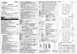
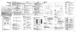
◆Dimensions
■Before use
Mounting screw:M4×10
ITEM/△key
◆Panel cut-out
92
1) Remove the mounting clips from the unit.
2) Insert the unit from the front of the panel.
3) Attach the mounting clips at the both side of the case
and secure in place with the screws.
(Tightening torque: approx. 0.2 to 0.3N・m)
・Applicable panel thickness: 1 to 5mm
±0.5
Keep enough space for several mountings.
recommended space:
130mm the left, right, top and bottom
from center of the unit
■Wiring diagram
1P2W
Terminal block A (upper)
2
X
Breaker
3
4
5
6
1
2
3
L
k
4
X
CT1
CT2
(To measure 3-circuit)
L
Terminal block B (lower)
1
k
2
V3
Vn
Measured voltage input
7
8
NC
SG
vacant
9
A+
10
B-
RS485
Terminal block B (lower) 8P
Terminal number
1
2
3
4
5
6
7
8
Functions
CT1
k
CT1
L
CT2
k
CT2
L
CT3
k
CT3
L
NC
NC
Measured current input
vacant
Power supply
Terminal No.
Single-phase two-wire
1- 2
Single-phase two-wire
3-6
Measured Single-phase three-wire
voltage input
Three-phase three-wire
Three-phase four-wire
3-5-6
3-5-6
3-4-5-6
3
4
5
6
X
X
X
X
X
X
5
6
k
L
CT1
CT2
K
k
2
L
3
4
k
L
5
k
K
A+ B-
85-264V
100-300V
0 - 500VAC [0 - 500V ]
◆端子台共通仕様
ネジサイズ: M2.5
締付トルク: 0.4-0.5N・m
接続可能電線(圧着端子をお奨めします):
単線 0.13-4mm2 (AWG26-12)
より線 0.2-4mm2 (AWG24-12)
8
SG
9
1
10
A+ B-
Breaker
2
3
4
5
□91 ±0.4
単相 2 線式
端子台 A ( 上段 )
X
2
ブレーカ
3
5
6
1
2
k
X
Class D
L1(R)
L2(S)
1
2
3
4
5
6
7
8
9
10
L+
N-
V1
V2
V3
Vn
NC
SG
A+
B-
AUX
(外部電源)
空き
端子
計 測 電 圧
3
L
k
4
5
L
6
k
L
◆推奨ブレーカ
3 -15A
(3 回路計測時 )
X
AUX
( 外部電源 )
X
CT1
電 L1(R)
源
側 N
CT2
CT3
負
荷
側
(3 回路計測時 )
K
単相 3 線式
三相 3 線式
L
端子台 A ( 上段 )
1
2
X
3
X
端子台 B ( 下段 )
4
X
5
6
X
X
1
k
2
3
4
L
AUX
( 外部電源 )
L1(R)
電
源 L2(S)
側
L3(T)
5
6
k
L
CT1
L1(R)
1
2
3
4
5
6
7
8
機能
CT1
k
CT1
L
CT2
k
CT2
L
CT3
k
CT3
L
NC
NC
操作電源入力
計測電圧入力
単相2線式
1- 2
単相2線式
3-6
単相3線式
3-5-6
3-5-6
三相4線式
3-4-5-6
X
6
X
X
1
k
AUX
( 外部電源 )
2
3
4
5
6
L
k
L
k
L
CT1
負
荷
側
CT2
CT3
◆通信接続図
エコパワーメータ
端子台 A( 上段 )
上位機器
RS485 機器
8
+
-
SG
9
10
A+ B-
エコパワーメータ
端子台 A( 上段 )
8
SG
9
10
A+ B-
◆VT を使用する場合
端子台 A
( 上段 )
ブレーカ
入力電圧
85-264VAC
100-300VDC
0 - 500VAC
三相3線式
X
5
K
L
Vn 端子は、 アース接地された N 相へ接続してください。 (CE 規格認証品として使用の場合 )
空き端子
端子間
X
4
N
SG
相および線式
X
3
L
端子台 B ( 下段 )
電 L2(S)
源
側 L3(T)
各端子に入力する電圧は表の通りです。
端子
2
負
荷
側
CT2
端子台 A ( 上段 )
ブレーカ
RS485
端子番号
L3(T)
N
For User's manual
You can download the user's manual from our website.
Anyone who needs help should contact us at the following.
◆推奨ヒューズ
タイムラグヒューズ
定格電流 2A
端子台 B ( 下段 )
4
1
計 測 電 流
X X
AUX
(Power supply)
Phone: 800.894.0412 - Fax: 888.723.4773 - Web: www.ctiautomation.net - Email: [email protected]
±0.5
K
6
VT
Connect terminating resistors to the both end of the
communication line including a upper device.
Connect terminating resistors (120Ω 1/2W or more)
between [A+] and [B-] of Eco-POWER METER
connected the end of RS485 line.
◆パネル取付
1)取付金具を本体から外してください。
2)本体をパネル前面から角穴に入れてください。
3)ケース左右の溝に取付金具をはめこみ
ネジを均等に締め付けて、ガタツキの
ないことを確認ください。
(締付トルク:0.2-0.3N・m)
締め付けすぎると変形のおそれがありますので
ご注意ください。
・取付可能なパネルの板厚:1-5mm
■結線図
端子台B(下段) 8P
Terminal block A (upper)
端子台B
取付金具
取付けネジ:M4×10
並べて取付ける場合は、十分な間隔を
確保して取付けてください。
参考間隔:上下左右 130mm (本体の中心から)
三相 4 線式
機能
L
Terminal block A Terminal block A
(upper)
(upper)
SG
92
2線接続の場合
(同一サイズの電線2本接続)
単線 /より線 2本 x 0.5-2.1mm2
(AWG20-14)
電線剥離長さ: 7-8 mm
端子番号
◆When using VT
◆Communication wiring
10
◆パネルカット寸法図
端子台A(上段) 10P
CT1
56
ITEM/アップキー
L
CT3
9
SHIFT/ダウンキー
液晶表示部
1
USB ポート
Input voltage
85-264V AC
100-300V DC
■端子結線について
端子台 B
8P
6
CT2
8
◆次のような場所での使用は避けてください。
・直射日光の当たる場所
・腐食性ガスや可燃性ガスの雰囲気中
・塵埃、鉄粉、塩分の多い場所
・水、油、薬品などのかかるおそれのある場所
・直接振動や、衝撃が伝わるような場所
・高圧線、動力線、または大きな開閉サージの
発生する機器の周辺
◆端子配列
AUX
(Power supply)
N
-
◆安全のため以下の条件にてご使用ください。
・過電圧カテゴリ:Ⅱ、汚染度:2
・屋内使用
・使用温度範囲: -25-+55℃
・使用湿度範囲: 30-85%RH(20℃にて)
結露なきこと
・標高2000m以下
Terminal block B (lower)
1
14
MODEキー SETキー
ブレーカ
L
L3(T)
+
●エコパワーメータは、省エネ目的の自主管理用の商品です。課金目的には使用できません。
また、計量法に定める指定機関が行う検定に合格した特定計量器ではありませんので、
電力量の証明には使用できません。
●エコパワーメータは、制御盤内に設置して使用することを前提に設計されています。
●火災・故障・誤作動や感電の原因となりますので、記載された仕様範囲内で使用してください。
・定格にあった電源に接続してください。
・電源・入力・出力は、結線図を参照し正しく配線してください。
・全ての電線サイズは定格電流に適合したものを使用してください。
・活線工事は行わないでください。感電または短絡やCT2次側開放のおそれがあります。
●計測電圧、計測電流の入力線は、高圧線・動力線との平行配線、同一電線管配線を避け、
できるだけ短く配線してください。
●全ての配線が終了するまで電源をONにしないでください。
●インバータの2次側回路では使用しないでください。本体の発熱や故障の原因になります。
●計測する電線にノイズが加わると正確に計測できないおそれがあります。
●エコパワーメータの配線作業は電気工事・電気配線などの専門技術を有する人が行ってください。
●エコパワーメータの汚れは柔らかい布などで乾拭きしてください。
(シンナー類を使用した場合、本体の変形・変色などのおそれがあります。)
●表示部に強い力を加えないでください。内部の液晶の破損のおそれがあります。
端子台 A
10P
Vn terminal should be connected to N-phase which is grounded.
The input number 6 of terminal block A has to be connected to protective earth
to ensure installation safety.
SG
Phase and wire system
2
4
L2(S)
Upper device
RS485 device
The input voltage to each terminal is as follows.
Terminal
L1(R)
1
3
L
(単位: mm)
(68)
端子台A
●異常発熱や発煙を防止するため、本製品の保証特性 ・ 性能の数値に対し余裕をもたせて
使用してください。
●分解、改造はしないでください。 異常発熱や発煙の原因となります。
●通電中は端子に触れないでください。 感電のおそれがあります。
●非常停止、インターロック回路は外部で構成してください。
●電線やコネクタは確実に接続してください。
接続不十分な場合は、異常発熱や発煙の原因となります。
●製品内部に液体、可燃物、金属などの異物を入れないでください。 異常発熱や発煙の原因となります。
●電源を入れた状態では施工 ( 接続、取り外しなど ) しないでください。 感電のおそれがあります。
◆背面から見た図
Load side
V2
6
◆外形寸法図
●本製品の故障や外部要因による異常が発生しても、システム全体が安全側に働くように
本製品の外部で安全対策を行ってください。
●燃焼性ガスの雰囲気では使用しないでください。 爆発の原因となります。
●本製品を火中に投棄しないでください。 電池や電子部品などが破裂する原因となります。
●端子結線は、端子配列・結線図を参照のうえ、間違いなく確実に行ってください。
●安全・機器保護のため、操作電源入力部には必ずヒューズまたはブレーカを接続してください。
また計測電圧入力端子は、電源スイッチ、遮断器、およびヒューズを内蔵して
いません。必ずこれらの装置を本器の近くに別途設けてください。
●全ての配線が終了するまで操作電源をONにしないでください。
Load side
AUX
(Power supply)
V1
5
CT3
Load side
Functions
N-
4
L
N
Power
supply side
L+
3
6
k
◆Recommended breaker
3 to 15A
L1(R)
Breaker
2
5
L
(To measure
3-circuit)
X
AUX
(Power supply)
Terminal block A (upper) 10P
1
◆Recommended fuse
Time-lag fuse
Rated current 2A
Terminal block B (lower)
k
X
◆Terminal arrangement
Terminal number
■取付方法
■ご使用前に
◆Panel mounting
Power
supply side
USB port
Terminal
block B
Mounting clip
SHIFT/▽key
Display
Power
supply side
Terminal
block B
8P
ケガや事故防止のため、以下のことを必ずお守りください。
(25.6)
(25.6)
MODE key SET key
◆Common for terminal block A,B
K
Screw size: M2.5
Terminal block A (upper)
1P3W/3P3W
Tightening torque: 0.4 to 0.5N・m
1
2
3
4
5
6
Applicable wire:
(Crimp-type terminal is recommended.)
X X
・single wire 0.13 to 4mm2
Breaker X X X
(AWG26 to 12)
AUX
・stranded wire 0.2 to 4mm2
(Power supply)
L1(R)
(AWG24 to 12)
L2(S)
・for 2 pcs.
L3(T)
single wire / stranded wire
2pcs. x 0.13 to 2.1mm2 (AWG26 to 14)
3P4W
Terminal block A (upper)
Stripping length: 6 to 7 mm
Terminal
block A
10P
(70.4)
□91 ±0.4
Terminal
block A
1
◆Back view
安全上のご注意
56
□96
■Wiring
●Be sure to wire correctly according to the wiring diagrams.
●Please connect fuses or breakers to the power supply input part for safety reasons
and to protect the device.
This product has no built-in power switch, circuit breaker or fuse.
Therefore it is necessary to install them in the circuit near this unit.
●Do not turn on the power supply or input until all wiring is completed.
14
±0.5
◆For your safety, make sure to satisfy the following conditions.
・Overvoltage category:Ⅱ, Pollution degree 2
・Indoor use
・An ambient temperature of -25 to 55℃
・An ambient non-condensing humidity of 30 to 85%RH (at 20℃)
・Altitude of 2000m or less
◆Do not use in the following environments.
・Where it will be exposed to direct sunlight
・Where inflammable or corrosive gas might be produced
・Where it will be exposed to excessive airborne dust or metal particles
・Where it will be exposed to water, oil or chemicals
・Where direct vibration or shock might be transmittted
・Where the place near high-voltage cable, power line or machinerys which occurs
the big switching serge.
□96
92 ±0.5
●Eco-POWER METER is designed chiefly to manage saving energy.
It is neither intended nor can it be legally used for billing.
●Eco-POWER METER is designed to be used installing in a control panel.
●Please use Eco-POWER METER according to the specification described.
Otherwise, it may malfunction or cause fire and an electric shock.
・Connect Eco-POWER METER to the power supply in compliance with the rating.
・Refer to the wiring diagram to ensure proper wiring for the power supply, input and
output.
・Use an electric wire applicable to the rated current.
・Do not perform wiring or installation with a live line. It may also lead to circuit burnout
or fire by way of the secondary CT side opening.
●Do not connect voltage input, current input, pulse input wires parallel to high-voltage
or power cables and avoid using the same conduit.
Use shielded wires as short as possible.
●Do not turn on the power supply or input until all wiring is completed.
●Do not use at secondary side circuit of inverter. It might cause exothermic heat or
damage.
●If additional noise effects power supply line, voltage input line, current input line,
incorrect measurements may result.
●Installation and wiring must be performed by expert personnel for electrical work or
electric piping.
●Please wipe dirt of the main unit with soft cloth etc.When thinner is used, the unit might
deform or be discolored.
●Do not add an excess power to the display. It might break the inner liquid crystal.
(unit: mm)
(68)
ご使用になる前に必ずこの施工説明書をよくお読みいただき、正しく施工してください。そのあと、
大切に保管し、必要なときにお読みください。尚、詳細はユーザーズマニュアルをご覧ください。
(70.4)
■How to mount
Read these instructions carefully for proper installation.
After installation, keep it in a safe place for reference when required.
保管用
施工説明書
KW9Mエコパワーメータ
92
KW9M Eco-POWER METER
2
3
4
5
6
X X
VT
85-264V
100-300V
[0 - 500V ]
http://panasonic.net/id/pidsx
© Panasonic Industrial Devices SUNX Co., Ltd. 2013
1
AUX
( 外部電源 )
D種
上位機器も含め伝送路の両端に接続される機器には、
終端抵抗を取り付けてください。
RS485 ラインの終端に接続されるエコパワーメータには、
[A+][B-] 間に 120Ω 1/2W 以上の終端抵抗を接続してください。
L1(R)
L2(S)
L3(T)
N
マニュアルについてのお問合せ
・ユーザーズマニュアルは 当社のホームページよりダウンロードできます。
・本品の詳しい使用方法およびマニュアルなどにつきましては、下記の連絡先までお問い合わせください。
<コールセンタ・フリーダイヤル> TEL:0120-394-205 受付時間: 月曜日から金曜日の9時∼17時(但し、祝日、年末年始等を除く)
8A3 F77 7000 2
PRINTED IN JAPAN